How to draw for 3d printer
How to Turn Your 3D Printer into a Plotter in One Hour | by Uri Shaked
Teach Your 3D Printer How to Draw and Write on Paper with Pens, Color Pencils, Crayons and More! 🖍
Building a plotter was on my list for a long time. A plotter is a device that can draw text and pictures on paper using a pen. A few weeks ago, after fellow Israeli makers built a small plotter from old CD drives, I decided it was finally time to build my own plotter.
I sat down and started planning the hardware, when I suddenly realized that there might be a nice shortcut — my 3D printer already includes all the hardware and electronics I need, I just need to figure out how to attach a pen to it and how to tell it to draw.
One hour later I had a working prototype. It was much easier than I initially expected. In this blog post you will learn how you can make your own printer draw.
This will be your 3d-printer’s first drawing! 📝Turning a 3D Printer into a 2D Printer 🖨
You might be wondering what is the utility in turning a 3D printer into something that can draw 2D pictures on a paper. After all, conventional printers do that for several decades already, isn’t that a step backward?
First, who said everything I make has to be useful?
Second, a plotter allows you to draw with pen, colored pencils, crayons, markers, and even a quill. Basically everything that can leave marks on a piece of paper. You even draw on different materials, such as cardboard or glass. You can also get creative with unique ink types, such as golden, silver or glow-in-the-dark —you name it.
Step 1 — Attaching a Pen
You want to reliably mount a pen to your printer’s head and ensure that the tip of the pen goes a little below the nozzle. I started by designing a small part of this purpose. It clips to the printer’s head, and I use a small M3 screw to fix the pen to it:
You can get the model here. It should fit any Creality Ender-3 or CR-20 printer, and possibly other Creality printers. It is also customizable, so you can tinker with the dimensions (if you want to fit a larger marker, or need a tighter fit with the printer).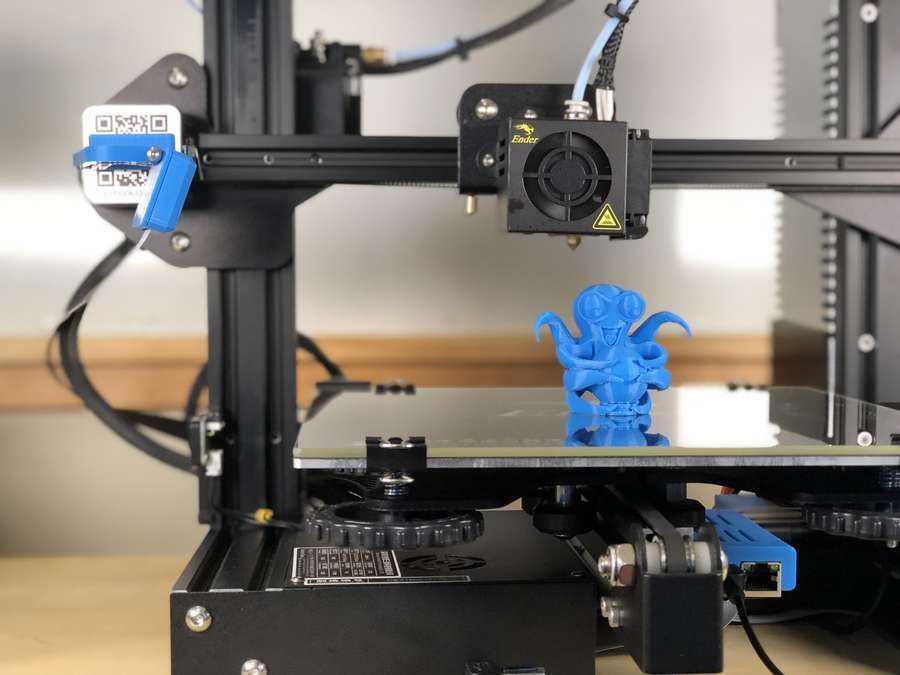
For other printers, you will need to design your own mounting mechanism (when you do, please share a link in the comments). While is it also possible to use screws for mounting the pen, I personally prefer the clipping mechanism as it allows me to switch between 3D printer and plotter modes really quickly, and also change pens really quick.
Step 2 — Calibration
Once you have successfully mounted your pen to your printer, it’s time to calibrate it. You will need to attach a piece of paper to your printer’s bed:
Pen mounted, paper attached, ready for your command!Next, you will need to find the correct height for printing. I recommend using Repetier Host for this (I initially started with Cura, but Repetier Host made everything much easier, so I will stick with it for this tutorial).
Before starting, make sure your printer’s bed is level and that both the nozzle and the printer bed are cool.
After homing your printer, go to the “Manual Control” tab inside Repetier, and move the print head up until the tip of the pen goes above the paper. Then, move your X / Y axis to the edge of where you want your drawing to be. Finally, move the Z axis down in 0.1mm increments, until you see the tip of the pen touching the paper. You can then move the X/Y a little and check that the pen actually leaves a trace on the paper. When done, note the X/Y/Z values that appear in the top line:
In my case, the values were 47 for X, 40 for Y and 14.6 for Z. We will use these values shortly when we generate the GCode file for printing.
Step 3— Choosing a what to print
That’s a tough one. So many options. You will need to get it in vector format, though — so if you use Google Images, add the text type:svg at the end of your search query. You can also convert JPEG and PNG images to SVG, but I’d suggest to start with something that already comes as a vector to make things simple.
Step 4 — Generating GCode
When I started this project, I thought I was going to spend some hours on getting the hardware right.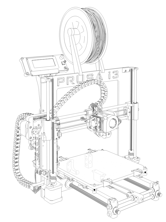 I was surprised how quickly I got the hardware part working. The software was, however, a completely different story — as always, software is where the real complexity lies.
After spending several hours on research, I finally found a workflow that works pretty reliably, though, it requires some setup. Other than Repetier Host mentioned above, you also need to get Inkscape (which is, by the way, also useful if you want to create PCB art!).
Inside Inkscape, create a new file and go to File menu → Document Properties (Shortcut: Ctrl+Shift+D). Then set the document size a little smaller than your print bed size, and also make sure you use mm for the units.
Once you have set the size, you can import any SVG file that you like, or simply draw some text using the Text tool:
When done, with the text still selected, click on Path menu → Object to Path (Shift+Ctrl+C). This will convert the text into a series of points connected by lines, which is required for feeding into the printer. You can add more elements such as spirals and star shapes, repeating the “Object to Path” operation for each:
When printing, objects won’t be filled, so you may want to remove their fill color and set their stroke color to black (or whatever color your pen is), so you get a more accurate representation of the final result. Select all the objects (Ctrl+A) and then remove the fill and apply black color for stroke (Ctrl+Shift+F):
Set the stroke paint color to blackWhen you are happy with the result, it is time to generate the GCode for the printer! We will use an extension called “Gcodetools”, which comes bundled with Inkscape (if not, you have an older version and need to upgrade).
We will start by defining the Orientation Points, which tell the printer how to map the lines on screen onto the paper. Go to Extensions Menu → Gcodetools → Orientation Points… and after making sure “2-point” mode is selected click Apply and then Close. You should now see two new text elements added at the bottom of your drawing:
These are the Orientation Points. Each point is a list of X, Y, Z coordinates that specifies the target location of that point in the Printer’s coordinate system. You need to edit them to match the X / Y you found in the calibration step, and set the Z (the third coordinate) to 0.
Edit the text on the left point and update it to contain the X / Y coordinates that you found. In my case, it was (47; 40; 0). For the right point, add 100 to the X value, copy the Y/Z from the first one, e.g. (147; 40; 0):
Next, we need to generate a tool and configure its speed. This step is optional, but if you don’t do this, your printer will draw really really slow. Go to Extensions menu → Gcodetools → Tools Library…, and select “default” in “Tool types”:
Click Apply and then Close, and you should see a green rectangle with a lot of settings added to your drawing:
You can move this rectangle away (together with all the values) so it doesn’t come over your drawing.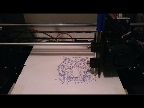 Then, you want to edit the text and change the values for “Feed”, “Penetration Feed”, “Passing Feed” to set the movement speed of the printer when drawing. I use 4500 for all of them (the unit is mm/min, so this value corresponds to 75 mm/sec).
We are finally ready to generate the GCode! Select all the elements in your drawing (Ctrl+A), and go to Extensions → Gcodetools → Path to Gcode…
There, go to the Options tab, and set “Scale along Z axis” to 1, and “Offset along Z axis” to the Z value that you found in the calibration step, minus one (I found 14.6, so I set it here to 13.6):
Next, go to the Preferences tab, and set the name of the output file and the path of the directory when you want it to be saved. You can also set the Z safe height to a lower value, to speed up the print (I use 5):
Finally, switch to the Path to Gcode tab, set the Depth Function to 1 and click Apply. It will take a few seconds and might spit a warning about no paths selected which you can safely ignore. You should see a new layer on top of your drawing, showing the moves of the print-head in the generated Gcode file:
At this point, I suggest opening the .gcode file in a text editor and verifying that the it looks legit — especially that the Z values there match the calibration value that you found:
Generated GCode! Note the Z value is 14.60000 hereI also suggest editing the first G00 line and adding F4500 at the end, otherwise, your printer might make the initial head movement really slow:
That’s it! You are ready to print. Load your Gcode file in Repetier host, and you should see your drawing on the screen:
Say your prayer, click the “Start Print” button and… enjoy the show!
Congratulations! 🎉
Your 3D printer now also doubles as a plotter. You can take it one step further and experiment with the different settings of Gcodetools — for instance, you can configure it to change the height of the pen according to the color of the line, thus making the plotter draw thinner/thicker lines. You can also use the “Area” function to fill shapes instead of just drawing the outline. ⭐
Please keep experimenting and try different types of pens and materials, and post you results in the comments — I’d love to see how far you can take this!
This is my 5th post in my Postober challenge — writing something new every single day throughout October.
I will tweet whenever I publish a new post, promise! ✍
How to Turn a 2D Sketch into a 3D Printed Part in 3 Easy Steps
Do you have a concept sketch that you want to turn into a 3D Printed part? Read this guide to learn how to turn a simple 2D sketch, drawing, or image file into a 3D Printed part.
Learn how to turn your simple sketches into 3D Model files and 3D Printed parts.
If you can make a simple drawing, then you can make a 3D Printed part.
Getting from your sketch to a final 3D Printed part requires just one step in between: creating a 3D Model in STL file format.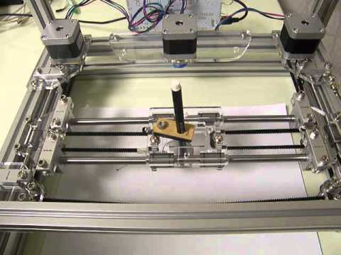 See this blog post to learn a little more about what 3D Model is, and why you need one in order to start 3D Printing.
This guide will walk you through how to transform your 2D sketch into a 3D Model file in STL format, and then how to use the Hollywood 3D Printing instant 3D Printing quoting tools to order your 3D Prints online.
Step 1: Make your Sketch with Dimensions
In this guide, we'll focus on turning this simple 2D outline of an anchor into a 3D Printed part. This shape outline will be copied 1-to-1 in a 3D CAD program, and then assigned a thickness to turn it into a three-dimensional model.
Your drawing should have a basic outline of your part, with any important dimensions included.
While this is a relatively basic task compared to the complex design geometry that 3D Printing is able to reproduce, it's nevertheless a foundational concept in 3D Design. Understanding how to turn a simple sketch outline into a 3D Model is the first step towards creating more detailed 3D shapes.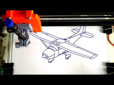
There are two things you want to make sure you have here: a sketch trace, and any dimensions that are important to your final part.
Sketch Trace: This is the outline of the part you'll be creating. This can be drawn free-hand; lines don't have to be perfectly straight, and you don't need to be good at drawing circles. Luckily, the design tools covered in the next step of this article will take care of this perfection for you.
Dimensions: Define the overall size of the item you'll be creating. For a 2D shape, this can be only one dimension such as the overall height or width -- but if you have other areas where hole sizes or widths are important, you can call these out as well. For this anchor piece, we'll be focusing on only the overall height dimension to start. Then, when we're done creating our 3D Model, we can use a software measurement tool to check against the other dimensions written on the sketch.
Once you have your sketch ready, just take a picture of it -- or scan it to an image file -- and then you're ready to start creating your 3D Model design.
Step 2: Creating a 3D Model from Your Sketch
If you're new to the world of 3D Design software, creating a 3D Model from scratch may sound like a daunting task. While it's true that the 3D Design process can be a very in-depth process requiring skill and experience, you'll see here that the process of creating a 3D Model from a simple 2D sketch is quite simple.
The first thing you'll need is a 3D Design program. We recommend Autodesk Fusion 360 because it's free to start and easy for beginners, but it is also an incredibly powerful platform that will allow you to create just about anything you can imagine as you become more experienced in using the software.
While it might be more comfortable to use a more basic lighweight design tool, you'll thank yourself later for starting out with Fusion 360. Let's jump right in!
Draw a line defining your object height: When you launch Fusion 360, you'll have a new design open and ready.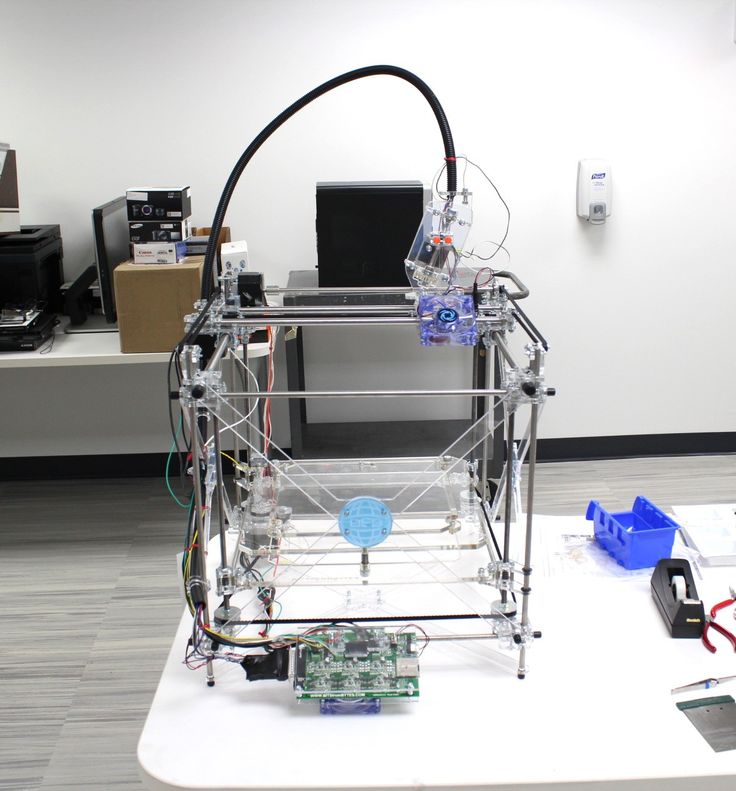 Press the "L" key to draw a line. This will first prompt you to select a sketch plane, so click any of the three options. We'll use the horizontal plane for a nice top-down view. Click anywhere to place your first point, and then as you go to place your second point, you'll see a text box appear. Type your height dimension into this box, and hit Enter to draw the line.
Congratulations! Now you have a line that matches the height of the anchor in the drawing. When you add your sketch image in the next step, you'll have a visual aid to help you scale the image to match this height dimension.
Import your sketch image: While still in Sketch mode, click Insert -> Canvas from the top tool menu, and select the image from your computer.
This will import your sketch into your CAD software, and then you can use the placement and sizing tools to get your image to be the same height as the height line you drew in the previous step.
When you've got your trace lined up with your height line, click OK to exit the canvas import menu. Now you're ready to trace over your sketch and create a flat profile of your shape in this 3D CAD software.
Trace the image: To trace this image, we'll use the Circle tool, Line tool, and Fit-Point Spline tool. We start off with the Circle tool, and place the center points in the middle of the round areas, and draw the circles out until they overlap with the drawing.
Use the line tool to trace over the straight areas of the drawing, and the Fit-Point Spline tool to place points along the areas of the drawing which have curvature. The Fit-Point Spline tool will create a curve which traces along the points you place one-by-one.
Since this is an object with symmetry along the vertical axis, meaning that it looks the same on the left half as it does on the right half, then we can save ourselves some time by mirroring the sketch across a vertical axis.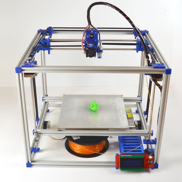 Once you trace the left half of the drawing, you can use the Mirror tool to create that sketch geometry flipped over on the right axis.
After selecting and mirroring the left-half geometry we traced manually using the Circle, Line, and Fit-Point Spline tools, we now have a full trace of our drawing. Now it's time to create a solid three-dimensional object from this sketch geometry, using the Extrude tool.
Extrude the sketch geometry: Select the Extrude tool, and click all of the closed sketch faces that you want to give a thickness to, and type in the thickness you want them to be. We want this part to be 10mm thick, so we type in 10mm into the Extrude tool box after selecting the sketch faces, and this gives us our final 3D Model of our anchor.
Now you have completed the process of creating a 3D Model file from your sketch. We just need to save it off in the right format for 3D Printing.
Saving as an STL file: From the Bodies section in the model tree on the left of the design area, right-click the model body, and select Save as STL.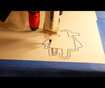 Name your file, and click Save. Now you're ready to 3D Print this STL file.
Step 3: 3D Printing Your STL File
The hardest part is over -- once you have your STL file, getting a 3D Print is simple.
When you create a user account at Hollywood 3D Printing, you get 10% off your first online 3D Printing order. You also get free access to a suite of helpful online 3D tools.
On sign-in to your Hollywood 3D Printing user account, you're directed to a blank new quote which is ready for uploading your 3D Model files in STL, OBJ, STEP, or IGES file format. This is where we're going to be uploading the STL file created in the previous step of this guide.
When you sign in to your user account, you're directed to a blank New Quote. This is where you can upload 3D Model files and get an automatic 3D Printing quote and order parts online.
To order a 3D Print of your 3D Model file, just drag+drop your STL file over the upload icon in this window, and it will appear as a new Line Item in your automatic online 3D Printing quote.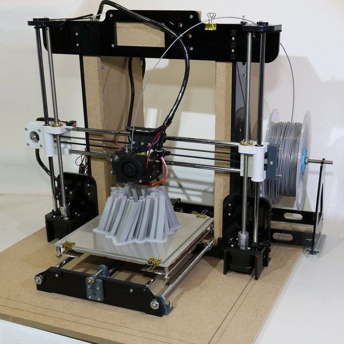
Once your 3D Model appears as a new line item in this 3D Printing quote, you can click the "Generate Price" button. This step is where our online 3D software analyzes your 3D Model file, and determines the size of your part, how long it takes to 3D Print, and the volume of material required by the part. Based on this information, you will see a quoted price to 3D Print your 3D Model.
After adding a 3D Model file to your automatic quote, you will see a "Generate Price" button appear. Click this button, and our online 3D software will analyze your 3D Model file and generate a 3D Printing price.
Along with this pricing information will be the dimensional size of your 3D Model. If the default choice for the 3D Model dimension units is not right, you can change your units by clicking "mm", "cm", or "in" in the Set Units section, and you will see your dimensions update.
In addition to changing the dimension units, you can select your build material option, and change the quantity of your order if you're looking for more just one part.
Upon generating a price, your 3D Printing quote will include a thumbnail image of your part, and a link to view your 3D Model in the online 3D viewer software.
From here, you are ready to proceed to checkout, and your 3D Printed part will ship to you within a matter of days.
Thanks for reading this guide! If you got this far, hopefully you now understand how to go from a simple 2D sketch to a finished 3D Printed part. We look forward to becoming your trusted 3D Printing partner.
Get Inspired
Browse through hundreds of examples of our 3D printing, 3D design, and custom fabricated builds.
Drawing on a 3D printer or Hephaestus trying on Picasso's beret
Good evening everyone!
It's no secret that the best feature of DIY printers is the incredibly wide customization and modification possibilities of the 'car'. From attaching more extruders and expanding the printable area to turning the printer into a food or musical instrument (seriously, the guys on YouTube are already moving steppers to the beat of the music). Or, for example, some make their printer draw. This is what I did today as well!
Preparing for.
In order to bring this daring plan to life, you will need:
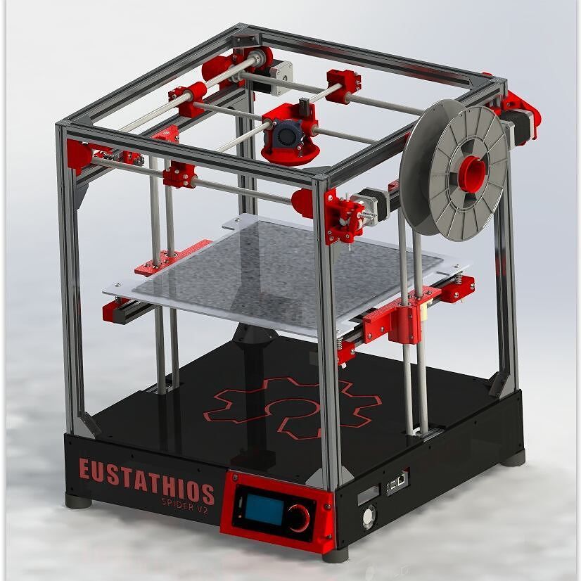
1) Printer, which plays the main role in this event. I heartily recommend the Prusa i3 Hephestos (if only for the simple reason that I have used it myself). But, in theory, any DIY or Open Source printer will do.
2) Soft. You will need the Inkscape program, which can be downloaded for free, and the gcodetools plugin for it. About what, how and where - further in the text.
3) Positive attitude on board and some free time.
Item A. An upgrade that makes your printer feel 'naked'.
For the movie magic to happen, you have to 'remove' the extruder. Those. all, including the bracket. Speaking on the example of 'Hephaestus', then in the end you should have only the printed platform-holder left from the extruder on the printer. I strongly recommend doing this carefully so as not to solder the wires to their rightful places later. After the job is done (I have no doubt about you, in the end you somehow assembled this DIY into its current state), you need to install a pen holder on the platform.
You can download them from the well-known site. Here are the holder links for
- RepRap: www.thingiverse.com/thing:31983
- Hephestos: http://www.thingiverse.com/thing:627774/
Personally, I printed the holder with 15% infill and thickness layer 0.3 - no problems experienced. The holder itself can be mounted on the same bolts that were used to mount the extruder. The result is such a nice design:
A few words about the calibration and the level at which you install this same pen. Personally, I did it extremely simply - through the level plate I brought it to the point when the printer brings the extruder to the center of the platform and set the handle so that there is a sure contact between the tip of the rod and the paper previously installed on the platform. The method, of course, only works if the platform is pre-calibrated. But tough guys don't look at the explosion and don't calibrate the table, so that shouldn't be a problem.
Item B. Preparing to transfer beauties and not-so-beauties onto paper.
As mentioned above, you need to download Inkscape. You can download it from the official site at this link. And here you can download gcodetools. The contents of the archive must be unpacked to *Inkscape installation location*shareextensions. Create a separate folder for the plugin DO NOT NEED . When all these boring items are completed, feel free to run the program.
[IMG ID=3063 WIDTH=514 HEIGHT=289]
Initially, I really wanted to draw a patriotic pin-up beauty, but life makes its own adjustments. It should be noted that in general gcodetools was created for extremely serious CNC guys, and therefore I have been digging into it all day, but some functions are still not given to the Padawan. If not today, then tomorrow all pin-up beauties will be drawn, but for now we have to curb our appetite - let's circle this drawing!
With a habitual movement, we throw this guy in . jpg directly from the desktop into the program workspace. Immediately, by the way, in file-> document properties I recommend setting the size of the drawing area. I set it to 180 x 180mm, well within the hephestos print area.
Now let's bring the drawing into a state that our printer can handle. Let me remind you that he can only operate with a pen - that leaves us with only the shaded and unpainted areas. Go to Path->Trace Bitmap.
The main setting we are interested in is Brightness cutoff. This setting is worth fiddling with. The value that suits me is 0.450. It doesn't have to be the same for you. Before clicking 'ok', make sure you have the image selected that you want to convert like this. Also note that the result will appear ON TOP of the original.
Now go to extensions-> gcodetools-> Path to Gcode.
Here we change, first of all, the cutting order to Pass by Pass.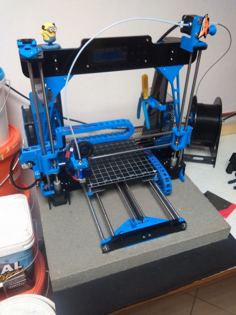 Thus, the handle will not make unnecessary gestures. I'm not entirely sure I understand her, but the guys in the know say, 'Believe me. and then you'll understand. Then go to the preferences tab. Everything is simple here - the file name, the path where it will be saved, and z safe (as you might guess, this is the distance that the pen will rise when it needs to move - the standard 5 mm is enough).
VERY IMPORTANT: be sure to add .gcode to the end of the file name. Otherwise, there will be no kin.
After playing around with these options, return to the path to Gcode tab. With a feeling of maximum dignity, press Apply. Warnings will pop up that you haven't set orientation points and tool, so the whole thing will be set to 'default'. We are satisfied with this option, click 'OK'.
Finally, your file is ready. We fill it on a USB flash drive and send it to the printer for 'drawing'.
The process, it must be said, is fascinating.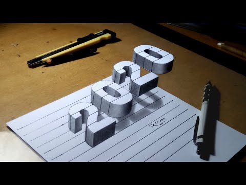 For those who are 'long' - I turned the speed up to 300%. Things went extremely well without any collateral damage. The printer finished drawing in about half an hour:
Personally, I am completely satisfied with the result. For those who were waiting for a pin-up beauty, not this tin can - as you can see, by creating a file in this way, we get a 'stroke'. Accordingly, the printer does not paint over areas filled with black. This can be easily solved if you dig deeper into the plugin settings and Area in particular. If necessary, I will show and tell you more in a separate post or comment.
Thank you all for your attention, stay with us. Drawing printers, big guys in bat suits and educational projects are guaranteed. Further more!
FDM 3D printing guide for beginners. Understanding Basic Terms
Getting started with 3D printers doesn't have to be intimidating. We have created this simple 3D printing guide for beginners to help all beginners understand the basic terms.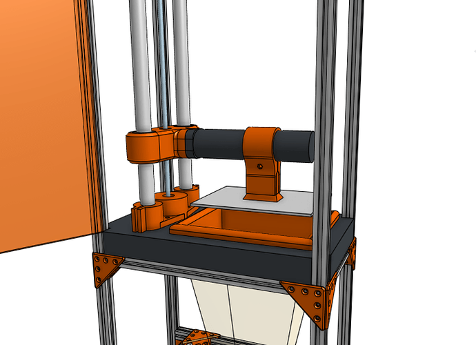
3D printing is a very general term. The media, especially mainstream marketing, portray 3D printing as the magical technology of the future, capable of reproducing complex objects.
But this approach makes it difficult to understand what 3D printing is from a technical point of view.
In reality, there are many different 3D printing technologies, but the most common for beginners is the layer-by-layer modeling method (FDM or FFF), which is the focus of this article.
Ender 3 V2 is one of the most popular hobbyist 3D printers.
FDM prints parts using thermoplastic, which is basically a filament of material that can melt, cool, and solidify. Details are built by stacking layers on top of each other.
This technology was created because people needed a way to quickly prototype parts. Even today, rapid prototyping is one of the biggest advantages of FDM and 3D printing in general. Not surprisingly, 3D printing is also gradually becoming a powerful manufacturing solution.
Before we get into the details of how FDM works, there is one more thing worth mentioning. If you have done some research on FDM, you may have noticed that some sources use the term "FFF" instead of FDM when referring to the technology. This is because FDM is a term originally patented by Stratasys and FFF is a non-proprietary generic abbreviation. Remember, this is the same technology, only the names are different. Today, most people use the term FDM.
FDM 3D printing. How it works?
- 3D printer control interface
- 3D printing plastic (filament)
- Extruder
- Hotend (hot end)
- Fan (cooler)
- Print platform (table)
- 3D printing
The easiest way to understand how FDM works is to study the details of an FDM 3D printer. However, before we get into the specifics, it's worth mentioning that most 3D printers can move in three axes: X, Y, and Z. The X and Y axes are responsible for moving left, right, forward, and backward, while the Z is responsible for vertical movement.
Now let's look at the main components of a 3D printer:
Control interface : Some modern 3D printers have a touch screen that is used to control the 3D printer. On older printers, a simple LCD with physical scrolling and a click wheel may be present instead of a touch interface. Depending on the model, an SD card slot and a USB port may also be present.
Print Bed : The bed or table of a 3D printer is essentially the surface on which parts are made. Platforms are most often made with heating to improve the adhesion of the part, but more on that later.
Extruder(s) : The extruder is the component responsible for melting and progressively depositing the plastic filament to build the model.
The extruder actually consists of two sub-components: hot and cold. The hot end or hot end contains a heater and nozzle that actually melts the filament, while the cold end consists of a motor, drive gears and other small components that push the filament into the hot end to melt.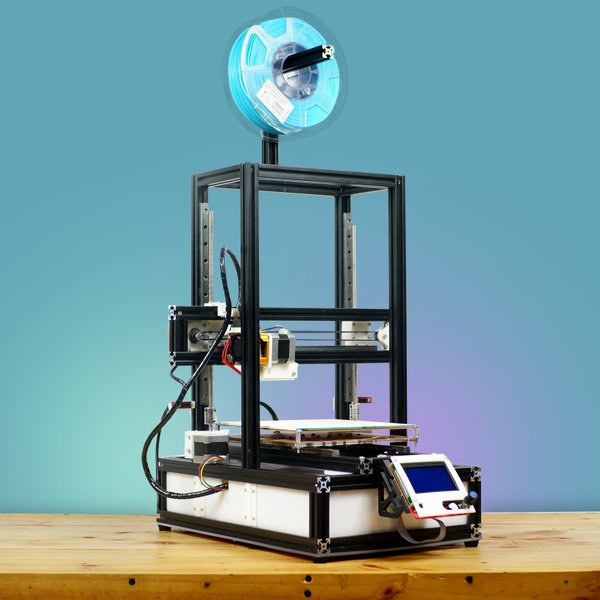
There is a heatsink and fan between the hot and cold ends because it is necessary that the cold end stays cold to avoid jamming.
In addition to the heatsink fan, there is usually at least one other fan to cool the molten filament after it exits the extruder - this is commonly referred to as the parts cooling fan.
Print head : one or more extruders are installed on the print head (standard 3D printers have one extruder). At the top of the print head is a tube that feeds filament into the print head.
How a 3D printer prints.
The process starts when you send the 3D model file to the printer. After starting a print job, the nozzle starts to heat up. When the nozzle reaches the temperature required to melt the filament, the extruder draws the filament into the hot end in preparation for deposition modeling.
The printer is now ready to 3D print the part. The print head descends onto the build surface (platform) and begins to fuse the filament, which cools and solidifies shortly after exiting the nozzle thanks to the part cooling fans.
Plastic is applied one layer at a time, and after one layer is completed, the printhead moves up the Z-axis a short distance and the process is repeated until the part is completed.
Create, download and purchase 3D models.
Naturally, if you want to 3D print a part, you must have a 3D model of that part. 3D models are created using 3D modeling software commonly referred to as CAD (computer-aided design) software. Here are some examples of popular 3D modeling software:
- Autodesk's Fusion 360 (Free for non-commercial use)
- Blender (Free)
- ZBrush (paid, but free trial available)
However, most newcomers to 3D printing do not have the skills required to use such software. If so, don't worry because there are other solutions.
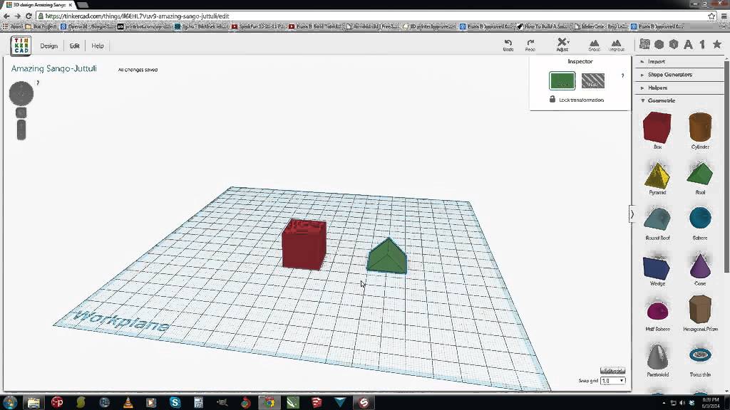
First, there are simpler CAD software options like Tinkercad, a program that almost anyone can use without any prior experience. This is an online application developed by Autodesk, one of the leading developers of CAD software.
File downloads
With so many people having access to 3D printers in recent years, several sites have become repositories for 3D models.
Some of the most popular are:
- Thingiverse (free)
- MyMiniFactory (many free, some paid)
- Cults3D (free and paid)
- CGTrader (some free and most paid)
- PrusaPrinters (all free)
So anyone can get their hands on a model without any modeling skills.
Model preparation.
3D models must be prepared for 3D printing using special software that translates the model into machine instructions. This is done using slicing software, also called a slicer. 3D models are imported into a slicer, which then actually "cuts" the model into layers. The resulting files consist of a G-code, which is essentially a long list of instructions that a 3D printer follows to build a model.
G-code is the "language" of 3D printers and CNC machines. These files contain important parameters needed to create a model, such as print speed and temperature, wall thickness, infill percentage, layer height, and many others. In other words, 3D printing is impossible without G-code files!
Supports (support structures)
Another of the main functions of the slicer is the generation of support structures (supports). In particular, supports are needed for parts with attachments.
9The 0004 Slicer allows you to choose where to place the supports and how tight you want them to be. Some slicers even offer users the ability to select different types of support structures for easier removal or strength.Printer preparation.
Before you start printing on a 3D printer, there are a few mandatory steps to take:
Plastic loading: The extruder must be ready to extrude the filament before printing begins. The loading process begins with heating the hot end to the melt temperature, and then the filament is directly loaded into the heated extruder.
Platform Leveling: In order for the printer to successfully print an object, the table must be as level as possible.
Depending on the printer, platform calibration can be performed manually, semi-automatically or automatically.
Platform leveling is very important because, for example, if the nozzle is too far from the table, the first and most important layer will not adhere to the surface, resulting in you not being able to print your object.
Materials for FDM 3D printing.
As we have already mentioned, FDM 3D printers use spools of plastic as part material. Filament is basically a thermoplastic specifically designed to melt and cool while maintaining its structural integrity.
3D printing filaments usually come in two diameters: 1.75mm and 3mm (or 2.85mm). Most 3D printers use 1.75 diameter plastic, which is why the variety of types and shades of 1.75 filament significantly exceeds 2.85.
We recommend that before you buy a 3D printer, be sure to clarify which filament it works with.
Converting the extruder from 2.85 to 1.75 is possible, but requires fiddling, time and additional accessories.
One of the best things about FDM 3D printers is that they can handle a wide range of plastics.
Here are just a few of the different types that are used in FDM 3D printing:
Standard:
- PLA
- ABS
- PETG
Engineering:
- Flexible (TPU, TPE)
- Nylon
- With additives (wood, metal, etc.)
- Polycarbonate (PC)
For supports:
- HIPS
- PVA
Among other things, FDM filament is one of the cheapest materials used in the world of 3D printing.
Post-processing of printed products.
Post-processing is the final steps you must take to complete your object.
Below we have listed some of the post-processing steps for a 3D printed part. You don't necessarily need to complete each of these steps.
Most often, post-processing is completed at the stage of removing supports.
Support Removal : After printing, the support structures are mechanically removed by simply breaking them off. As a result, you can see marks left on the surface of the part.
If you have bought a 3D printer with two extruders, you can use special soluble plastics to print supports. In this case, you just need to place the object in water if you printed with PLA+PVA or in limonene if you printed with ABS+HIPS.
Sanding : Your part may have imperfections (eg after removing supports). In this case, grinding comes into play. Light sanding of 3D printed parts can make the surface smoother.
Coloring : You will often print in one color. To add more colors, details or protection, you can paint your model!
Polishing or Smoothing : Epoxy is one way to smooth the surface of a printed part. For ABS, an acetone steam bath is often used. Under the influence of acetone vapors, ABS begins to dissolve and, if this process is stopped in time, you will get a smooth and glossy part.
Gluing : If you want to print a large 3D model that won't fit in your printer's build chamber, you can print two or more parts and then glue them together.
Common 3D printer problems.
Let's discuss some of the most common problems beginners may encounter when using a 3D printer.
Warp : This problem occurs due to temperature differences during the 3D printing process. 3D Print Delamination - 5 Tips and Tricks to Avoid Delamination.
Plastic bleed (snot) : Thin extra filaments of plastic on your model may be caused by incorrect temperature or retraction settings. Some types of plastic, such as PETG, are more prone to free flow from the nozzle.
Nozzle Clog : Nozzle clogging is one of the most annoying problems of FDM 3D printers.
If you hear a strange printhead sound and no plastic comes out of the nozzle, the nozzle may be clogged. This can be caused, for example, by poor filament quality or incorrect temperature settings.
Layer Offset : This problem can be caused by vibrations and wobbles in your printer, insufficient X and Y belt tension, or excessively high print speeds.