How to calibrate 3d printer bed
How to Manually Level a 3D Printer Bed
(Image credit: Tom's Hardware)Whether you’re using a brand new 3D printer for the first time or noticing that your prints come out uneven or, even worse, fail to stick, you need to level the print bed. Entry-level 3D printers, even those which sit among the best 3D Printers, often do away with luxuries like color screens, direct drives and probes for automatic bed leveling. Don’t worry, learning how to level a 3D printer bed is not hard; it just takes a little practice.
“Leveling the bed” is a bit of a misnomer. We’re actually “tramming” the print surface: making sure the nozzle is at the same height across the bed at every point on the X and Y axis.
Level is a simple, if not precise, word everyone can understand.
The biggest problem when manually leveling a 3D printer bed is finding the correct distance between the nozzle and the print surface. Too far and your prints won’t stick. Too close and you’ll damage the print surface.
Luckily for those of us stuck with manual 3D printer bed leveling, we don’t need to be laser accurate. We’re dealing with fractions of a millimeter, so pretty darn close will get us the quality we seek.
When Do You Need To Level a 3D Printer Bed?
- After assembly and before your first print.
- After changing the nozzle to make sure the nozzle remains the correct distance from the bed.
- Once a week. Even the best printer can fall out of calibration with use, so check your level occasionally.
- After a failed print. Prints not sticking? You might be out of level.
What You’ll Need to Level Your 3D Printer Bed
- A Piece of Paper: This is used to gauge the distance between your nozzle and the print bed. Computer paper is a good choice, but a piece of junk mail or a Post-It Note will work too.
- Filament: Load your printer with PLA for running a test print.
 PLA is a commonly used filament and sticks well without fuss. We’re using Inland PLA + Orange for this article.
 - Isopropyl Alcohol : Clean the print surface before leveling. Filament never sticks well to a dirty bed.
- Paper Towel: For cleaning the bed.
- Slicer App: You’ll need to slice your test print – any slicer will do. We like to use Ultimaker Cura.
- Bed Level Test Print: There are several files online, we’ll use this one from Thingiverse. It’s sized for an Ender 3. You can size this one to fit your printer’s bed or search for a test that’s made for your specific machine.
- Your 3D Printer: In this article, we’re using a Creality Ender 3 Pro FDM 3D printer. The four-point print bed is similar to many popular 3D printers on the market today, including the Elegoo Neptune 2.
Prepare your Printer
1. Clean the bed. Lightly scrub the print surface with Isopropyl Alcohol and a paper towel to remove fingerprints and any bits of leftover filament.
2. Preheat your printer and bed to its normal operating temperature. For PLA, we warm up the printer to 200° on the nozzle and 60° on the bed. Wait at least 5 to 10 minutes to let the printer absorb the heat.
Some experts believe it's unnecessary to preheat the bed, as the possibility of heat expansion is very small. We prefer to level the bed under the same conditions we use while printing.
3. Home the printer. This will take it to the 0,0,0 position.
4. Check your printer controls for an option called Bed Leveling, Level Corners or Bed Tramming. This option will move the printer around the four corners of the bed while you adjust the springs underneath.
A few Ender 3 models come with leveling aids installed. You’ll need to select “Disable Steppers,” which turns off the stepper motors and allows you to push the print head by hand.
Note: Our Ender 3 Pro has been upgraded to Marlin 2 firmware, which added a Bed Tramming routine.
5. Slide the print head (or let the printer do it) to the first corner, centered more or less over the adjustment knob under the bed. Slip a piece of paper under the nozzle.
6. Use the adjustment knob underneath the bed to raise or lower the nozzle until it barely touches the paper.
Do this for all four corners and the center. Then do it again. Leveling the bed is a balancing act where adjusting one corner can throw off the opposite corner.
(Image credit: Tom's Hardware)Run a Test Print
1. Load a bed level test print into your slicer of choice. Since we’re using a Creality Ender 3 Pro, we’ll use one found on Thingiverse called “Ender 3 Bed Level”. If your printer has a larger or smaller print surface, adjust the x and y coordinates accordingly.
2. Reduce the Z height to 0.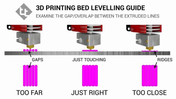 4 for a single layer test print.
3. Clean the bed with Isopropyl Alcohol and a paper towel.
4. Run the print.
Diagnose the Results
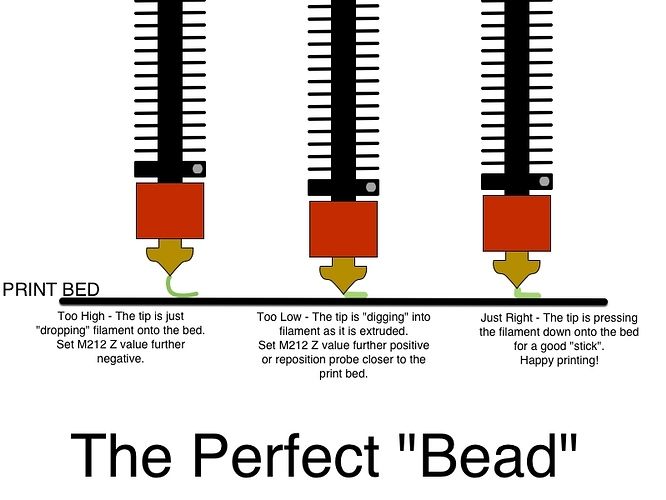
- Nozzle is too close. If your nozzle is too close to the bed, it will plow through the filament, causing a rough, uneven surface. You could have thin patches where the plastic is being pushed into the bed surface. It may be difficult to remove.
- Nozzle is too far. If your nozzle is too far from the bed, there will be gaps between the lines of filament. The lines of plastic appear rounded and may not stick to the bed at all.
- Nozzle is just right. When the nozzle is a perfect distance from the bed, it will appear slightly squished or lightly flattened. Lines will blend into each other with a uniform appearance. There will be very little roughness.
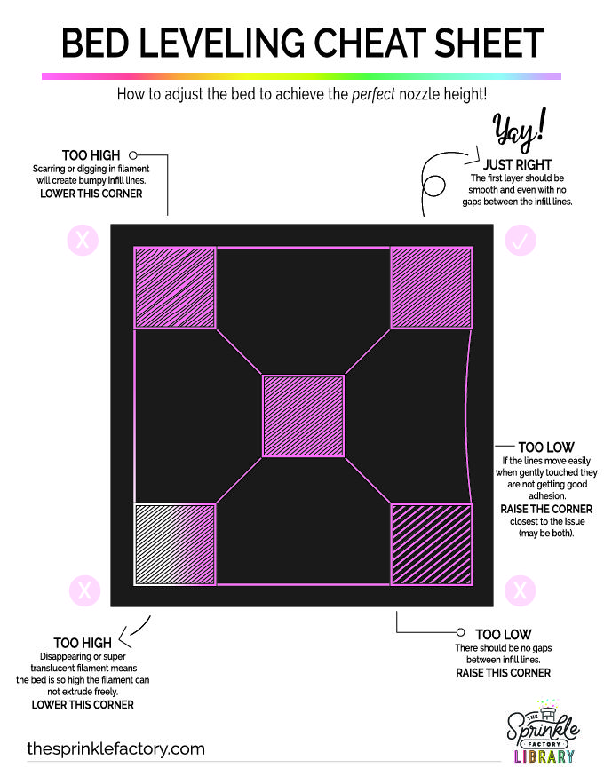
If the squares of the test print appear too far or close to the nozzle, make adjustments as needed and re-run the test print.
3D Printer Bed Leveling Aids
It can be difficult to achieve a perfect first layer with manual 3D printer bed leveling. Here’s a few things to try before you give up and buy a BL Touch Auto Sensor , which can be used to do auto leveling on an Ender 3-style 3D printer.
- Clean the Bed. A squeaky clean bed is extremely important for bed adhesion. Even a few fingers prints can add enough grease to make a print not stick.
- Use a Raft. Your slicer can place a chunky first layer down that helps tall or delicate prints stick. The downside is that you’ll have a rough surface on the bottom of your print. You will find rafts under Build Plate Adhesion in Cura and under Support Material in PrusaSlicer. Other slicers have their raft options in other menus.
- Use Glue Stick. A washable disappearing glue stick – the purple kind – from the children’s craft aisle is a perfect adhesion helper. It lays down a tacky layer that helps filament grip the surface. Lightly smear the glue across the whole bed, then wash off after 3 or 4 prints and reapply. The brand doesn’t matter, so feel free to stock up during the next Back to School sale.
- Shim the Bed. Warped beds are sadly common in inexpensive printers. If your bed seems lower or higher in the middle – and you have a removable print surface – you can shim the bed with aluminum foil, masking tape or even a Post-It Note.
To Shim the Bed
1. Remove the print surface.
2. Place a steel ruler or similar straight edge on the bed and shine a flashlight behind it.
(Image credit: Tom's Hardware)3. Note how big the gap is and cut a piece of foil or tape approximately that size.
4. Place it on the printer bed and look for gaps with the ruler.
5. Layer additional pieces of foil or tape until the bed is mostly flat.
6. Replace the bed surface and level the bed.
(Image credit: Tom's Hardware)Get instant access to breaking news, in-depth reviews and helpful tips.
Contact me with news and offers from other Future brandsReceive email from us on behalf of our trusted partners or sponsorsDenise Bertacchi is a Contributing Writer for Tom’s Hardware US, covering 3D printing.
Topics
3D Printing
3D Printing Essentials: How to Perfectly Level your Bed
For some, levelling a 3D printer's bed can be challenging, but it doesn't need to be. Read this essential guide to see what it takes to do it right.
Posted on December 30, 2020
by
Alec Richter
Part of the 3D printing experience is having an acute understanding of how the machine works and how to properly calibrate it to give you the best chance for success. Making sure that the first layer of every 3D print is the ideal distance from the bed isn’t the only factor in your 3D print’s success–you also need to ensure your 3D printer’s bed is universally level. Your first layer may look perfect in the front of the bed, but it’s also important to consider how well it’s sticking in the back of the bed as well. Leveling the bed of your 3D printer is an important step in getting high quality 3D printed parts, but it can be a little tricky. Luckily, the Pros at MatterHackers are here to help. Let’s take a look at the essential lessons of leveling your 3D printers bed.
What Does It Mean to “Level a 3D Printer’s Bed”?
First, there is the important distinction that what is colloquially referred to as “leveling your bed” would more accurately be called “tramming your bed.” The goal is not to have the bed level in relation to the floor (as you might imagine doing with a bubble level), but rather to have the bed be the same distance from the nozzle across the entire surface of the build plate OR put differently the bed parallel to the printhead gantry. This in fact might mean that if you take a bubble level to your 3D printer’s bed, you will probably find that it’s skewed. However, start a 3D print that runs across the entire bed and you’ll see the first layer is perfectly flat.
Simply put - leveling your printer’s bed is exactly as it sounds. You want to make sure your bed is level so there is a precise distance between the nozzle and the entire surface of the build plate. Now, you can’t just put a standard bubble level on your bed and call it a day, because again, the “level” we are looking for is between the nozzle and the print surface - not the nozzle and the workbench, desk, or floor that your printer is sitting on.
Manual Bed Leveling
In terms of construction, manually leveling, or adjusting your printer’s bed by hand, is the simplest form of bed leveling you will find on a 3D printer. Generally, the more affordable the 3D printer is, the more likely it will be a manually adjusted bed because it doesn’t require any complex calculations or extra hardware to make it work. A manually leveled bed will have the build plate itself floating above the bed carriage–it is not rigidly mounted to the bed carriage. Instead, the build plate is secured to the carriage using a combination of screws, springs, and thumbscrews. This combination makes it so the bed can pivot and be adjusted while still being rigid enough to not bounce around while you are 3D printing.
Manually leveling the bed is a tried and true method, as long as the bed itself is flat and doesn't have any unintentional contour.
How to Manually Level the Bed
Three points define a plane, but many printers still use four screws to level the bed, with one at each corner.
- Tighten down all the screws at each corner, so you have enough room to loosen them later. Aim for screwed down halfway instead of all the way or all the way off–this will give you more room to work with.
- Home the Z axis.
- On some printers, Z0 (home) may be too far from the bed, even when all the screws are loose.
 In that case, you’ll need to move the Z-minimum endstop slightly lower to calibrate.
 - Using the LCD menu or other interface, jog the printhead over each screw that levels the bed, insert a piece of paper between the nozzle and the bed, and loosen the screw until there’s a very slight resistance when you pull on the paper.
- You don’t want the piece of paper to be locked between the two, just enough pressure to feel the drag when you move the paper.
- Repeat this for the other screws.
- You want to make sure each screw pinches the piece of paper with the same amount of pressure to have a level bed.
- After adjusting all screws, check your work by moving the nozzle over the screws again and making sure they didn’t shift from previous adjustments.
- Start a print.
- You can make adjustments while the 3D printer is printing to fine tune your first layer.
Once your printer is leveled, it should stay that way for a while. However, it’s a good idea and maintenance practice to adjust or relevel your printer’s bed occasionally to ensure great prints every time.
Software Leveling
Ideally, manually adjusting the bed is enough to have a consistent first layer. However, depending on the quality of components used on a 3D printer, a bed may not be a uniformly flat surface to start with. In some cases, thinner 3D printer beds have a tendency to bow and warp as they heat up and cool down which means no matter how hard you try there will always be some point on the bed that will be lower or higher than the rest. Effectively, no amount of thumbscrew adjustment will compensate for a 3D printer with a bed shaped like a bowl unless you have some compensation routine, like software leveling.
What is Software Leveling?
Within MatterControl, our slicing software, there exists a guided wizard that will allow even the most extremely out of shape printer beds to have a uniform first layer. By manually mapping the bed of your 3D printer, MatterControl is able to adjust the Z values in the sliced Gcode so the nozzle is constantly moving up and down to achieve a consistent distance from the bed throughout the 3D print.
Using MatterControl to "software level" the bed will enable even the most dished and skewed bed to have 3D prints perfectly follow its contour.
How to Software Level.
You will need to connect your 3D printer directly to MatterControl by connecting the USB from the printer to your PC. Once the leveling is complete you can continue to 3D print from MatterControl or export the sliced Gcode onto an external device like an SD card or thumb drive.
- Connect your 3D printer to MatterControl.
- Under the “Controls” tab and “Calibration” subsection click “Printer Calibration”
- Follow the wizard
- Your printer will then home on X, Y, and Z and then move over the first point that needs to be calibrated.
- Insert a small piece of paper between the nozzle and the bed and slowly decrease the distance between until you feel a very slight resistance on the printer.
- Not enough to hold the paper tight, but enough to feel that it can’t easily slide around anymore.
- Repeat this process for every point of the grid until a mesh can be constructed.
- The most important thing is to have the resistance of the paper the same at every point so that it is uniform. A little too tight is fine as long as you use this measurement throughout the bed.
- Slice up a test print to check your work.
- A large rectangle that covers the bed will make it clear if any point is too close or too far at that particular point.
- Adjust the Z-Offset by baby-stepping further or closer to the bed.
After it’s all said and done, your bed itself won’t be level but your first layers will have a consistent distance from the bed which means your 3D print’s foundation will be adhered to the bed and lead you on the path to success.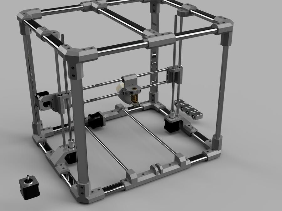 Be sure to run through this wizard again if you find that you are experiencing high or low spots in your first layer or adjust the number of points you have in your mesh grid if the trouble spots are between probe points.
Firmware Leveling
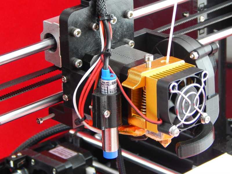
On some 3D printers, user intervention is kept to a minimum by a handful of features built into the firmware of the 3D printer, hard-coded into it to make finding the perfect first layer as hands-off as possible. By using a small probe to detect the bed and its relative distance from the Z minimum or Z maximum, the firmware is able to automatically run through a bed leveling procedure and construct a grid that will compensate for an uneven bed. Think of firmware leveling as essentially the same thing as software leveling, except the printer is doing all the thinking instead of you and a piece of paper.
After using a bed probe (seen glowing red) you can 3D print across the entire bed of a 3D printer without worrying about high or low spots.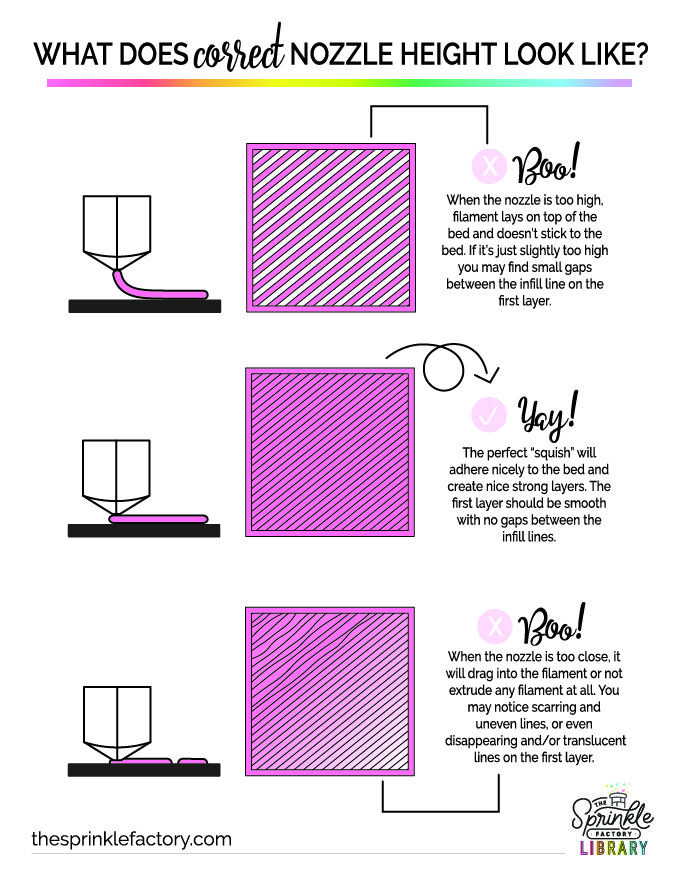
How to Firmware Level the Bed:
If your 3D printer has firmware leveling, it is likely enabled by default, rather than something you turn on if you want it. The best practice is to follow the instructions prescribed by the manual included with your 3D printer. Most 3D printers with firmware leveling will have a wizard (a guided walkthrough) incorporated into it to make set up easier. In general, the process will be similar across the different 3D printer and probe types:
- The nozzle and bed will heat up in order to allow them to expand and get a more accurate reading.
- The print head will move around the 3D printer probing various points to create a mesh of the detected surface.
- Either a series of lines will be printed to determine which Z-Offset works best, or a small test print will need to be started manually.
- The Z-offset will be adjusted through the LCD menu to move the nozzle closer or further from the bed to achieve a proper first layer and determine the distance between the probe tip and the tip of the nozzle.
Firmware leveling is a straightforward process that aims to simplify what used to be a significant hurdle for newcomers to 3D printing. By integrating automatic systems, it becomes easier to have repeatable results. Spend less time worrying about your 3D prints you just started and more time focused on slicing up your next one. There are many different probes that can be found on 3D printers, and you can check out our article on the different types to see what kinds of limitations, if any, your probe might have.
Whether you have a 3D printer that needs to be manually leveled or a 3D printer with fully capable firmware leveling, it’s important to understand the basics of how the process works to troubleshoot and calibrate your 3D printer as you become more acquainted with it. Hopefully, with the help of this guide, you now understand how to level your bed and get smooth and consistent bottom layers on your 3D prints. With this knowledge, you are well on your way to understanding the 3D printing essentials.
Happy printing!
Article Tags
- 3D Printing
- Firmware
- 3D Design
- MatterControl
- Press Releases
- Small Business
- Automotive
- E3D
- Jewelry Making
- Engineering
- Entertainment Industry
- MatterControl Touch
- ESD Materials
- NylonX
- BCN3D
- Open Source
- Crafty Pen
- Digital Fabrication Anatomy
- How To
- Hardware and Upgrades
- Tips and Tricks
- Weekend Builds
- Top Ten
- Education
- Tech Breakdown
- Women in 3D Printing
- Project Ideas
- Advanced Materials
- Reference
- Pulse Dual Extrusion
- Product Spotlight
- Aerospace
- Jobs
- Military & Government
- Multi-Tool Machines
- Getting Started
- Healthcare
- How To Succeed With Any 3D Printing Material
- Creality3D
- Architecture
- 3D Printer Reviews
- Hacker of the Month
Related Products
View all related productsTypes of tables for 3D printer
Contents
-
- Print platform materials
- Heated table
- Non-heated table.
- Table surface
- Types of calibration
- Automatic calibration
- manual calibration
- Calibration of a 3D printer table with Cartesian kinematics
- Calibration of the Delta printer 9000 9000
- Print platform materials
The correct calibration of the 3D printer bed, or as it is also called Hot Bed, is very important. The first layer is like a foundation for a house, if the foundation is fragile, then the house will not stand for a long time.
If the plane of the printed surface is uneven, then the model may be partially peeled off or deformed. The first layer may not stick to the printing platform at all, and the result of many hours of printing will not be a neat 3D model, but plastic noodles.
Print failure example
Therefore, it is very important to properly calibrate the table. Printing platforms can be conditionally divided into two types - adjustable and not.
The adjustable table is attached to the printer with spring-loaded screws. It is not rigidly fixed in height and with the help of screws it is possible to calibrate the plane and the gap between the 3D printer table and the nozzle.
Adjusting screw
Unregulated is a printing platform that is rigidly fixed to the printer body. This solution is used in delta printers. Calibrate them only programmatically.
Non-adjustable delta printer table
Print platform materials
The material from which the table is made may vary depending on whether the table is heated or not.
Heated table
There are several types of heating elements for a 3D printer platform - aluminum, textolite, silicone and kapton. Each of them has its pros and cons.
Textolite heater - inexpensive, but fragile and can be strongly bent when heated.
Silicone heater - can not be used alone. Usually used in conjunction with a metal base.
An aluminum table is expensive, but it heats up more evenly and is less subject to thermal deformation than other platforms.
The Kapton heater is very expensive and cannot be used on its own. Usually glued to a metal base. Can be heated up to 200 degrees.
Types of heated printing surfaces
Most often, an aluminum heating table or a silicone heating pad is used in conjunction with an aluminum plate. Low price, ease of processing and high thermal conductivity make aluminum the most popular material for the manufacture of heated printing tables.
The main advantage of heating the printed surface is to increase the adhesion (adhesion) of the first layer of plastic. If the printer is with a closed case and a heated platform, a “passive thermal chamber” is created inside. Due to this, plastics with high shrinkage do not crack in layers during printing, the adhesion of layers (interlayer adhesion) increases, and internal stress is more evenly distributed during cooling.
But there are also disadvantages - when heated, the metal table expands a little, and since it has nowhere to expand, it begins to bend. For a printing platform up to 200x200 in size, deformation will not be very critical, but for larger tables this becomes a tangible problem.
Each manufacturer of 3D printers with a large printable area solves the problem of deformation of the metal table in its own way. For example, in Raise 3D, the table is fixed along the entire plane with pins at 13 points.
Heated table fixing Raise 3D
Table without heating.
An unheated printable surface is often used in 3D printers designed to work only with PLA and other low temperature plastics. For example - printers for children or large printers with an open case.
An unheated printable surface is often used in 3D printers designed to work only with PLA and other low temperature plastics. For example - printers for children or large printers with an open case.
Children's printer with acrylic print bed
Tables without heating are made of aluminum or acrylic. If the table is aluminum, then glass or any other coating should be used on top. Aluminum is a soft metal and even a brass nozzle can scratch or damage it if not properly adjusted.
Heating table with aluminum base and mirror
Acrylic tables are often used in inexpensive 3D printers designed for kids. Acrylic is difficult to damage or break. You can print on an acrylic table without glass or other coating.
Free Shipping
Add to compare
Product added to compare Go
| Manufacturer | Raise3D |
Add to compare
Product added to compare Go
| Manufacturer | Raise3D |
Add to compare
Product added to compare Go
| Manufacturer | Raise3D |
Free Shipping
Add to compare
Product added to compare Go
| Manufacturer | Flash Forge |
Table top
In order for the first layer to adhere to the table tightly, different surfaces are used that increase adhesion. It is more convenient to remove the model from the removable surface. If you need to immediately start printing another model, you can simply quickly change from one removable surface to another.
The most popular table surface is the regular tempered glass or mirror. It is not expensive and available. It is believed that the accuracy class of the mirror is higher, but for small working areas (up to 200x200 mm), ordinary tempered glass is enough.
Glass itself does not hold the first layer well, so various adhesives or stickers are used to increase adhesion.
Ordinary glass can burst from a temperature difference or “crumble”, then the model comes off along with pieces of glass. Good thing it's easy to replace.
A piece of glass came off with model
Sitall glass - in fact, it is ordinary glass with the addition of boron oxide. This makes it stronger than ordinary glass and resistant to temperature changes. But the cost of such glass is much higher than ordinary or tempered glass.
Sitall glass
Perforated table - mainly used for printing ABS plastic. Thanks to the perforation, the plastic adheres firmly to the print platform. In order for the bottom of the model to turn out to be even in the slicer settings, you need to enable printing on a raft (substrate).
Perforated table used in UP printers!
Stickers - There is a huge variety of stickers for printing platforms. It can be either ordinary masking tape or a specialized surface (rough with an adhesive surface).
The finished model is easier to remove from a flexible substrate than, for example, from glass. With some substrates, the model can be easily removed after the printing platform has cooled down. For some, you need to heat the table and only then tear off the model.
Separately, you can select a variety of compositions that are applied to the surface of the printing platform to increase the adhesion of the first layers. 3D varnishes, 3D adhesives, etc. Probably every 3D maker has his own special recipe for the same composition that almost everything sticks to. It can be BF glue mixed with a solvent or alcohol, ABS diluted in acetone, kvass with sugar, glue stick, etc.
Do not spray varnish or other sprays inside the printer. Glue particles can settle on mechanisms, fans, and even get on electronics. This can lead to damage to the 3D printer. Simply remove the platen surface from the printer and apply the adhesive.
Add to compare
Product added to compare Go
| Manufacturer | Raise3D |
Add to compare
Product added to compare Go
| Manufacturer | Flash Forge |
Add to Compare
Product added to compare Go
| Manufacturer | Flash Forge |
Calibrations
In addition to choosing the surface of the print platform, it is important to correctly level the plane of the table and set the correct gap between the table and the nozzle. Calibration can be automatic or manual.
Printers with large print surfaces, such as the Raise 3D Pro 2 and Pro 2 Plus, are calibrated at the factory. The user only needs to check the gap between the table and the nozzle, because it may go astray during transportation.
Automatic calibration
Automatic calibration is performed using a sensor (optical or contact), which is mounted next to the extruder. The printer checks several points on the print platform one by one and remembers the values. The first layer will be printed correct for the curvature of the table.
You can meet the calibration using a conductive substrate that is placed instead of the printed surface. This method is rare, but still has a place to be. It is commonly used to calibrate 3D printers with delta or delta robot kinematics.
Automatic calibration allows you to quickly and effortlessly level the table. It becomes especially indispensable for printers with delta or delta robot kinematics. Optical sensors "do not see" glass, so for printers with an optical sensor, it is better to use other surfaces of the print platform.
Some printer models have a menu with hints to help you properly set the platform plane and gap. It is enough to launch the “assistant” and follow the instructions on the screen. This is not exactly automatic calibration, but with such help it becomes much easier for a beginner to correctly calibrate the table.
An example of a 3D printer with automatic calibration is Raise E2. The Raise E2 extruder has a contact sensor to determine the distance between the nozzle and the printed surface. The resulting values help to correct the print height of the first layer. You can calibrate not the entire table, but only the area on which the model will be located.
Manual calibration
Manual calibration is when the user sets the plane of the table and the gap between the table and the nozzle himself. To do this, under the printing platform there are screws or winglets with which you can adjust the height of the printing platform.
Calibration screws
The standard gap between the platform and the nozzle, for most printers, should be - 0.1-0.2mm. If there is no set of probes at hand, a standard A4 sheet folded in half can replace it. Before calibration, the print surface (if it is heated) and the nozzle must be heated.
Sometimes manufacturers of 3D printers recommend a gap between the table and the nozzle - 0. Therefore, read the instructions before calibrating.
We will consider the calibration of the two most common kinematics - Cartesian and delta.
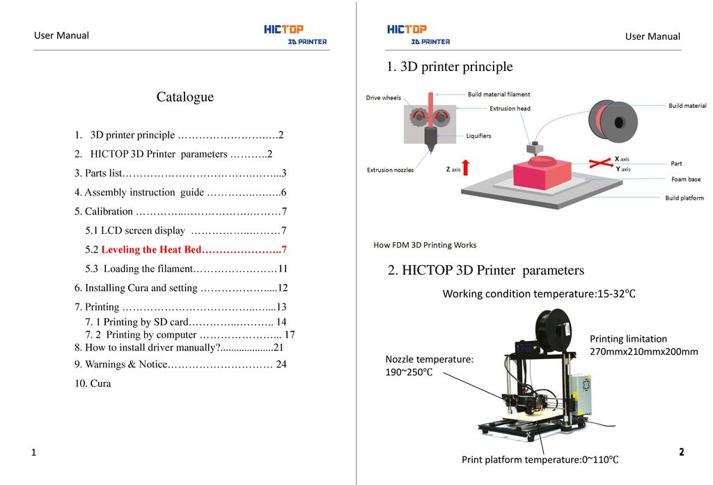
Cartesian kinematics is based on the Cartesian coordinate system and the movement of the 3D printer's head along the x, y, z axes.
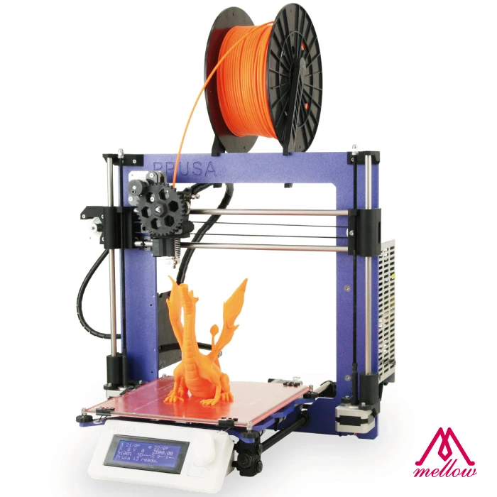
Printer example with Cartesian kinematics
In deltas, the extruder moves along 3 identical axes using carriages moving along vertical guides. The delta printer can be called a simplified delta robot, but these are still two different kinematics.
Example of a printer with delta kinematics
3D printer table calibration with Cartesian kinematics
Different manufacturers may have slightly different calibration instructions. We will consider here the calibration of the printer with standard kinematics.
-
Heat up the table and nozzle. When heated, the metal expands slightly, so the gap between the printing platform and the nozzle may differ between the “hot” and “cold” ones.
-
Through the printer menu, send the table and extruder to the "home" or zero position in all axes. Usually the zero point is the near left corner of the extruder and the top position of the print platform. Be sure to make sure that the 3D printer does not rest the nozzle on the table and does not damage it. If this is the first calibration, use the nuts to lower the table as low as possible.

-
Through the printer menu or manually (for this you need to turn off the motors through the menu), move the extruder so that the nozzle is above the adjusting screw.
-
Use a feeler gauge and adjusting screw to set the gap between the print bed and the nozzle.
-
Repeat all steps for all calibration screws. Usually there are 3 or 4 screws.
-
After aligning the plane above the screws, move the extruder to the center and check the gap. If the gap matches the feeler gauge, then the table plane and platform distance are correctly calibrated.
Delta printer table calibration
Calibrating a delta printer is a very large topic, so here we will only describe the general principles.
The delta printer does not have the x, y and z axes we are used to. Instead, the delta printer has 3 towers - A, B, C, on which the carriages move.
Since the delta table is static, it is calibrated programmatically.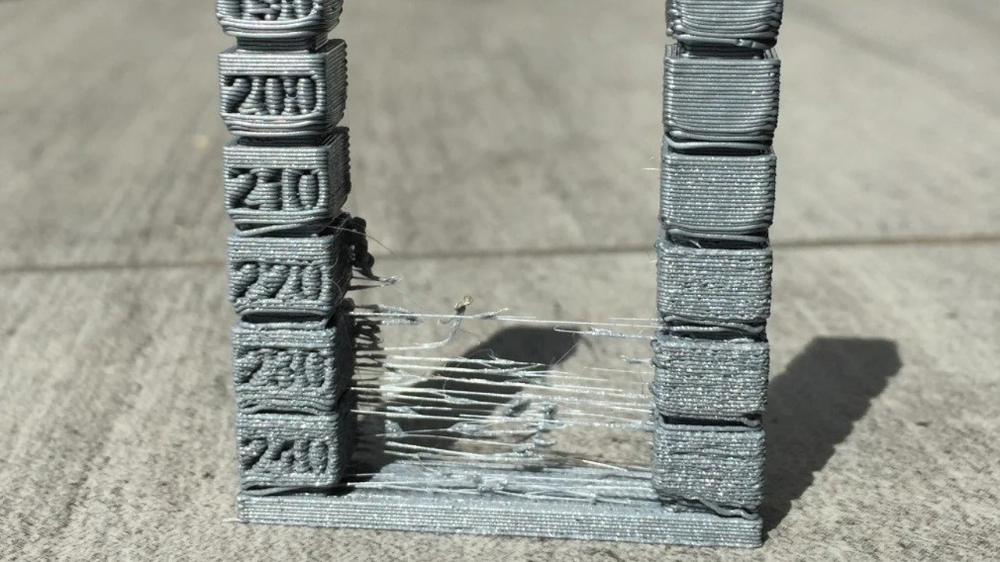 The gap is calibrated by 3 points (at the columns) and the lens (center) of the table. The lens can be concave or convex.
Before calibration, check the mechanics of the printer - the belts must be tensioned evenly, there must be no play in the carriages and the effector (the plate to which the extruder is attached). If the belts are loose or uneven, it will be problematic to calibrate the printer.
Some 3D makers check belt tension with a tuner. Evenly tensioned belts will sound the same, but the correct “note” is found empirically.
There are a huge number of programs for delta calibration, but one of two is usually used - Pronterface or Repetier-Host. Using them, you can directly access the printer using special commands and change the values in the firmware.
As auxiliary programs, you can use a virtual calculator and from there transfer the values \u200b\u200binto the firmware or download the finished GCode. They need to specify the parameters of your printer - firmware (usually Marlin or Repetier), diagonal length, circumference, etc. These parameters can be taken from the firmware or measured with a caliper. It is important to specify all the parameters as accurately as possible, otherwise the printer will not be able to calibrate.
First, 3 points are aligned at towers A, B, C, and only then the lens in the center of the table is corrected.
Manual delta calibration is tricky, but it doesn't have to be repeated often. Typically, the printer only needs to be recalibrated after some mechanical parts, belts, or print bed cover have been replaced.
Totals
The calibration process may seem tedious and complicated, but in fact, once you do it yourself, the process will no longer seem so intimidating. In addition, most manufacturers try to help novice users and equip their printers with auto-calibration sensors or try to simplify this process as much as possible with detailed menu prompts.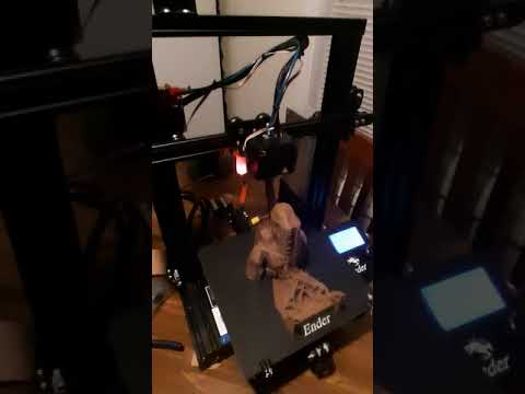
And a variety of coatings for a printed table will help you find exactly the surface that suits your needs. As practice shows, every 3D maker, novice or experienced, has his own proven way to make the first layer stick tightly.
Don't be afraid to experiment and let every 3D print be successful.
3D Printer Calibration / Sudo Null IT News
Sometimes the owner of a 3D printer has to do this. I will tell the habr-community about my method. Please note that the manual is detailed, but leads to excellent results - the model adheres perfectly and does not peel off during the printing process.
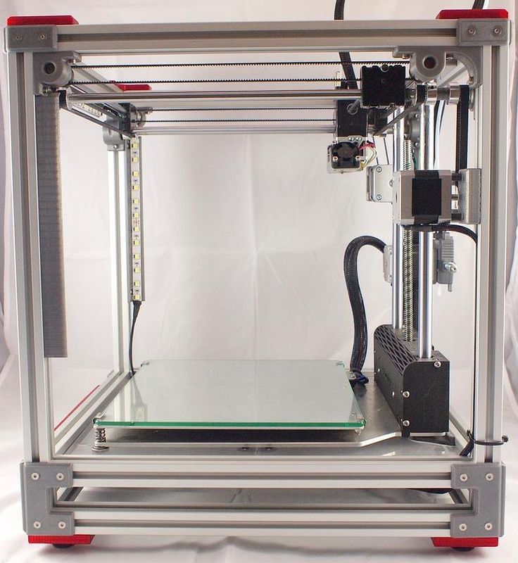
To begin with, I would like to note that I honed my skills on the SmartCore Aluminum printer purchased here.
Installing the heating platform
The heating (or non-heating, depending on the printer) platform must first be set in height. There is a limit switch for the Z axis for this purpose.
This trailer can be adjusted in height by means of a tightening bolt and clamping bolt.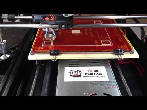
It is necessary to set it so that the surface of the platform clearly touches the extruder nozzle.
For further calibration we will use Pronterface from the Printrun software package.
The advantage of this package is the visual and convenient control of the nozzle and the printer platform, but if someone is more comfortable using Repsnapper, it is also quite suitable. Cura is not suitable for calibration, for lack of the necessary functionality for this.
To continue, let's make sure that when you press the "Home" button (white house is shown), the platform rises and rests closely, but does not try to move further towards the nozzle.
Since the firmware on my printer was taken directly from the SmartCore Aluminum repository (albeit not directly from Marlin), the nozzle goes to the middle of the platform. If this is not the case for you, and the nozzle remains in the corner at zero coordinates, it's okay, this is not important for further calibration.
Calibration
The following steps must be carried out in turn on the center, corners and reference circle:
- Click on the Z-axis calibration
- If the corner rests against the nozzle (the center should rest, as we achieved by adjusting the height of the limit switch during preparation), then we slightly press the platform bolt at this corner until a minimum clearance appears.
- We eliminate the minimum clearance, but no more. Ideally, we should have a nozzle that is clearly butt in all corners and in the center when you click on the Z-axis calibration. This is the result we need to achieve for high-quality printing, more on monitoring the result later.
- Now you need to make sure that when you click on , a gap will appear. If this does not happen, you can slightly release the bolt that presses this corner and, by successively pressing the green house, then the “0.1” button, repeat until the desired result is obtained.

After we finished the calibration at all five points and went through them so that we didn't have to change anything, we can proceed to check the calibration result.
Test
For testing, I use a simple model drawn in FreeCAD and gcoded in Cura. Plastic, the more accurate the diameter, the better - I take it here because of the declared accuracy and variety of colors. However, for verification, we will use the natural color of ABS plastic.
The meaning of a simple little test model is probably clear - saving money and time.
It is in this sequence that it makes sense to check. However, if you are confident in your calibration, then you can immediately start with step 2. Well, if you already have experience and you are absolutely sure of your calibration, then you can immediately go to step 3 - print 5pad.gcode.
The difference is in the number and arrangement of products.
I will describe the verification of the first step, since the rest are similar.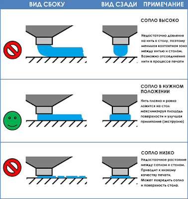
Suppose one side of the platform is too highly calibrated. It is very easy to find out as a result:
Top view:
And what is more important for us now is the bottom view:
- this is what the Cura rim looks like if the nozzle is located too high to the platform. Plastic does not fall accurately, sometimes clinging to neighboring lines.
Consider the opposite situation - if the nozzle is too pressed against the platform:
As you can see, not everything is smooth here either, the plastic, trying to fill the available space, will fit on adjacent lines, and on the next layer, the nozzle re-clings and smears again over the available space. However, it should be noted that in this case the model sticks very well, and the calibration defect is not visible on the next layers. Moreover, it may not even be noticeable at all if you choose a substrate in Cura for sticking the model to the table.
Finally, the desired and correct result:
Here you see a slight burning, but it is associated with an uncleaned piece of thread, which is clearly visible in the photo of the bottom view. Similar burns are rather inherent in the previous case, when the nozzle is too pressed. And the rest - smooth lines, tightly laid. That's the way it should be. Congratulations - the center point calibration is successful.
It is normal if such a result is obtained on glass at a temperature of 100 degrees. At the same time, if the glass is degreased and even, then after the end of the calibration, it will not come off during the printing process. You can try peeling the part off the heated bed after printing. Until it cools down to 90-80 degrees, you might not even be able to do it without damaging the glass. Also, the absence of a draft may be important, which affects the equally important uniformity of heating of the platform surface.
Here are general photos for easy comparison:
Top view:
Bottom view:
Further verification is similar in essence, but 4pad.gcode should be printed - covers a slightly larger central area. And 5pad.gcode - will show the quality of the calibration in the corners.