How to build your own 3d printer from scratch
How to Build a 3D Printer From Scratch
If you are reading this article that means that you’ve probably decided to join the community of 3d printing enthusiasts and find out more about 3d printers, or maybe you have already got some experience in it and are ready to try to create your own 3d printer from scratch.
In this article you will find general understanding how 3D printers can be built as well as links to really useful resources where you can find more detailed information with step-by-step description.
Currently there is a big variety of 3d printers in the Internet that already assembled and are ready to print right after you unpack them from a box, of course you also need to buy a 3d printer filament for it. Do not forget that not all 3d printers can use the same filament types, so please read the instruction before you purchase it.
But for some people who love to make something new with their own hands can be more interesting to build their own 3d printer from scratch. Based on our research the 3D printing community is filled with many enthusiastic people so called DIY’ers (Do It Yourself’ers), who are fascinated with building 3d printers literally almost from scratch.
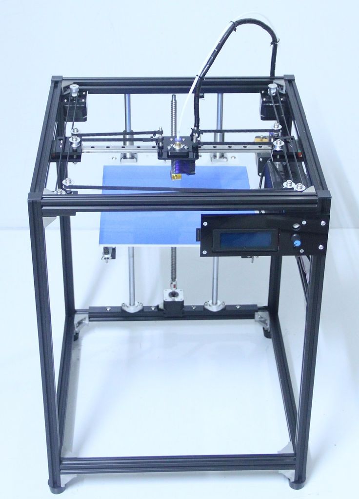
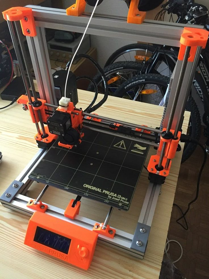
Good example of it is RepRap movement. RepRap is short for a Replicating Rapid-prototyper. In other words it is the self-replicating 3d printer. In fact most of today’s top consumer level 3D printers (picture above) are originated in one way or another from RepRap.
You can find a lot of examples on how to build a 3d printer from scratch on RepRap website, but we also want to describe some of more essential steps in order to give an overall understanding of what to expect if you really decide to make your own 3d printer.
The first step is to find and buy 3d printer DIY kit. Kits usually contain most of parts needed to assemble the printer and can be divided into two main types:
Scratch Built 3D Printer – This 3d printer DIY kit is for those who prefer to build thing from scratch, or in other words go to DIY RepRap route. Apart from some essential advantages this approach has also its disadvantages. In theory it can save you some money and since you build it from scratch you will know every nut and bolt in it by the time you can use it and successfully print your first object. Main disadvantage of this method is time. Literally it will take a lot of time to deal with all these hundreds of bolts, wires, belts and much other stuff. In the end you still need to select and purchase or build a controller board, but it depends on your skills level.
Kit Built 3D Printer – This type of kit is good if you want to save some money and at the same time not to deal with all challenges described in the 1st kit type. Many manufactures sell such kits with “easy-to-assemble” instructions included. I doubt that it will be as easy as assemble a chair from IKEA, so you still have to be mechanically inclined and able to understand basic geometry. Some of such kits contain not all parts and you may need to buy something in addition.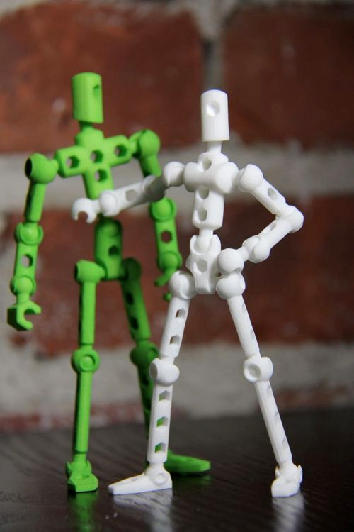
The next step will be to determine the design for your 3D printer. In my humble opinion most of DIY 3D printers have not very breathtaking and futuristic design in comparison with MakerBot and other brands. But it is also a matter of taste, for some people the design is not very important.
Once you have got your 3d print DIY kit and chosen the design you could go ahead and start the most fascinating and time consuming part – build your own 3d printer. Be prepared for sleepless nights and a lot of fun. Maybe you will make up something new and present your findings to RepRap community.
When the hardware part of the 3d printer is ready you also need to add a software component to it. It basically does the following things: allows you to view and alter 3d graphical objects, as well as converts the 3d images into instructions that 3d printer can understand.
Finally you can 3d print your first object! If you do not have anything to print, you can find a big variety of objects on specialized marketplaces such as Shapeways, Thingiverse and others. Before printing make sure that the object you want to 3d print has the right size and fit on the printer frame.
At the end there is a list of some links where you can find more information about how to build your own 3d printer from scratch:
- RepRap options
- 3D Printer DIY: How to Build Your Own 3D Printer from Scratch
- 3D Printing: Build Your Own 3D Printer and Print Your Own 3D Objects
- Arduino Controlled CNC / 3D Printer Hybrid
- El34 World – 3D Printer Build using 1 inch T-Slot extrusions
- CNET 3D Printer Build Week
Also watch a video from Ben Heck in which he answers on some 3d printing related questions.
Related Articles:
- What is 3d printing – 3D printing technologies overview
- What is 3D Printing?
- History of 3D Printing
- Direct and Binder 3D Printing techniques
- Photopolymerization and Sintering
- 3D Printing Process
- 3D printing revolution
- 3D Printing Materials
- How to choose a right 3D printer filament type
- 3D Printer Filament Types Overview
- Types of 3D printers or 3D printing technologies overview
- How to find and buy a right 3D printer
- History of 3D printing in one picture
- Places to download 3D printer files and files formats overview
- 3D Printing Services Overview
- You Should Know These Important 3D Printing Concepts
Building a 3D printer from Scratch - Electronics - Frame - Tips & Tricks
So you want to build an FFF / FDM 3D printer from scratch? Well here is a good place to start.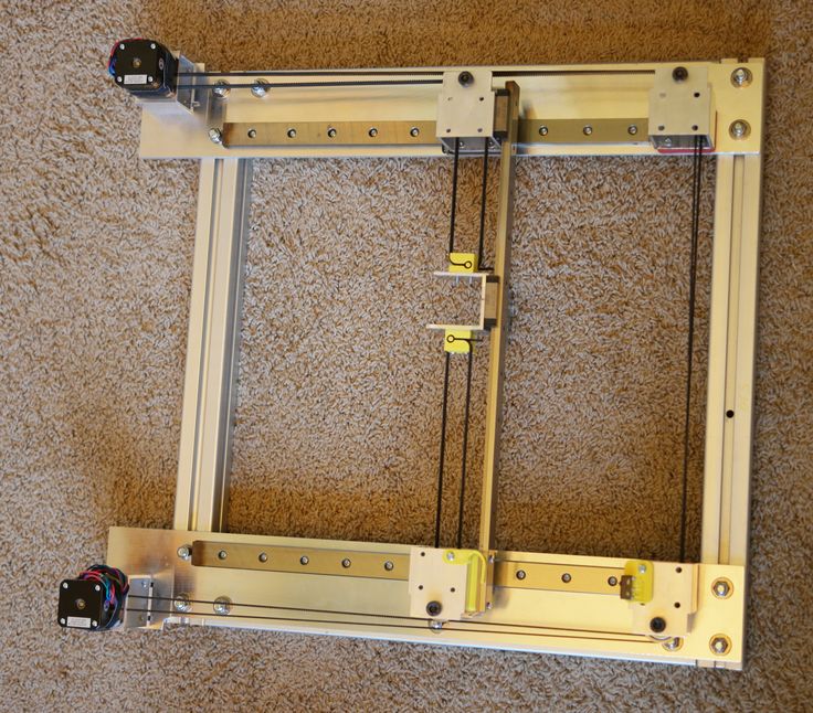 I’ll go a bit into different types of 3D printers and discuss the choices I made during the process.
Consider the two most common FFF / FDM design types to choose from:
- Delta
- Cartesian
Delta printers
Delta printers work with 3 different Z-axis driven motors in a triangle formation moving up and down to adjust the center position in the X,Y, and Z-axis all at the same time together.
Cartesian printers
Cartesian printers are straightforward X Y and Z-axis all working independently. There are 4 different main types: Mendel / Prusa, Darwin / Ultimaker, Corexy and H-bot.
I have built a Mendel / Prusa style printer and a Darwin / Ultimaker style printer.
For the purpose of this article, I’ll go into full detail of building these two types, and explain the basic details of these other types.
I’ll also go over parts and what’s okay to go cheap with, and what’s better to get the real products for.
- Prusa / Mendel Style 3D Printers
- Ultimaker / Darwin Style 3D Printers
- CoreXY and H-bot style 3D Printers
- Delta Style 3D Printers
Prusa / Mendel Style 3D Printers
The first type of printer is the most common style of 3D-printer. It originated as the Mendel, then the Prusa Mendel, and is now in the form of the Prusa i3. All of these have the same mechanics. Overall, once they are calibrated and dialed in correctly, the print quality is very good.
X-Axis and Z-Axis
These style of printers have a floating X-axis(gantry) that raises and lowers on the Z-axis while the print head (hot-end) moves back and forth on the X-axis. The gantry moves up and down with two leadscrews powered by 2 motors working in parallel. The leadscrews have the best results when they are paired with a bearing and linear rail as close as possible.
Y-axis
With these two axis alone, you can only print a flat wall. That is where they moving bed comes in. The Y-axis includes the entire bed and moves back and forth perpendicular to the X-axis. With all 3 of these working together, they can print 3D objects.
Bed leveling
Most beds are leveled with either 3 or 4 fixed points mounted on spring tensioned bolts. More recently, manual bed leveling has for the most part, been surpassed by automatic bed leveling. While it is convenient, it is still recommended to level the bed as best as possible to eliminate excess movement of the Z-axis.
Print platform
These style of printers may or may not have a heated print bed. I highly recommend having a heated bed. Not having a heated bed makes printing very difficult otherwise and it a minimal investment to add to a printer. And almost always having a heated bed, tempered glass is recommended over aluminum. Glass has less of a chance of permanently warping and is far more resistant to wear.
Belts and leadscrews
The X and Y-axis both use GT2 belts while the Z-axis typically use 8mm leadscrews.
Pros Prusa styled printers:
- These printers are relatively easy to build and are almost always fully open source.
- They are easy to troubleshoot with a general understanding of 3D-printing.
- More open area available / not enclosed.
- Relatively inexpensive.
Cons Prusa styled printers:
- These style of printers typically have issues with Z-axis wobble that shows an imprint of the leadscrews in the final print surface.
- Difficult to level bed due to gantry leadscrews also having to be adjusted.
- Slower printing due to mass of bed moving.
Ultimaker / Darwin Style 3D Printers
The second type of printer is notably known as the Ultimaker or Darwin. These are highly rated printers as they have very good print quality. They are a lot more difficult to build as they have a lot of moving parts.
X-axis and Y-axis
These printers have a hotend that is moved on both the X and Y-axis at the same time or independently. Both of the X and Y-axis have a linear rail that they move along. The X and Y-axis are affixed to the printer and do not move up or down. Imagine looking down at one axis. It would look like an H. The center part of the H is what moves up and down and the other axis would be the exact same, except sideways.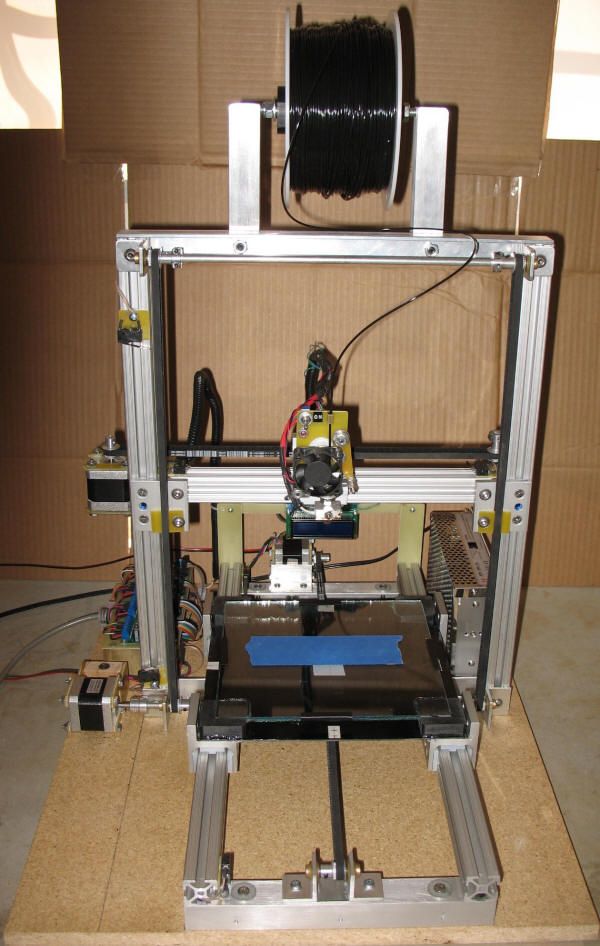 The hotend is connected to both of the center rails at a fixed point. If you move both axis at the same time from one end to the other, the hotend will move in a diagonal motion. Otherwise, each axis will move the hotend along it’s path if it’s the only one being moved.
There are 2 belts each for both the X and Y-axis. They are connected together via a moving rod that spins along with that axis of movement. At both ends of the rod, a GT2 Gear is connected. On the opposite side of the belts, there are bearings that allow free movement of the belts. The belts are connected at the point where the bearing of the axis moves along the linear rail. This way, the rod or rail is moved at both ends at the same time, resulting in a consistent movement. Any flex is eliminated that may occur from only one end of the rail moving. That flex would end up with horribly misshapen prints.
Z-axis
While the X and Y-axis have a lot of movement and are rather complicated, the Z-axis is pretty simple.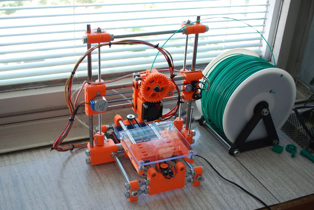
Typically, the Z-axis consists of only one leadscrew and two linear rails fixed at one end. This is only possible due to the rigidity of the bed base. Otherwise, for larger printers, or ones with weaker bed mounts, the linear rail / leadscrew combination would be needed on two opposite sides of the printer.
Print platform
These printers typically always have a heated bed. The first iterations however did not. These tend to either have plexiglass, tempered glass, or an aluminum plate.
Pros Ultimaker / Darwin Style Printers:
- Excellent print quality when calibrated and tuned correctly.
- Easier to level bed.
- Faster printing.
Cons Ultimaker / Darwin Style Printers:
- Has to be enclosed in a cube shaped structure.
- Difficult to troubleshoot if issues arise.
- More expensive due to parts needed.
CoreXY and H-bot Style 3D Printers:
These style of printers are similar to the Ultimaker / Darwin printers. The hotend moves along the X and Y-axis and are affixed to the printer and do not move up and down, but the controlling mechanisms are a lot more complex.
X-axis and Y-axis
The X and Y-axis are controlled by two motors working in unison to move the hotend forward and back on the Y-axis and left and right on the X-axis. It is a complex belt drive system that requires both belts to move in order for any movement to be made. If both motors turn in the same direction, the hotend will move along the X-axis. If they turn in the opposite direction, the X-axis gantry will move along the Y-axis.
Z-axis
The Z-axis is exactly the same as the Ultimaker / Darwin style printers.
Pros CoreXY printer and H-bot Printers:
- Can reach high speeds
Cons CoreXY printer and H-bot Printers:
- They look incredibly difficult to troubleshoot with a lot of mechanical parts that could have failure points.
Delta Style 3D Printers:
Delta printers are unique and rather complicated but yet gracefully simple at the same time.
Three or six faces
These printers are usually in a cylindrical shape with three or six faces. How they work is vastly different from the other style printers.
Arms
Affixed to 3 sides of the printers are the linear rail and belt mechanisms. There is an arm attached to each one of the belts that slides along the linear rail. The arms of each of the 3 side meet in the middle where the hotend is connected. When one arm moves up vertically, the hotend moves in the direction of that rail. When it moves down, it moves away. If two move up, the hotend moves towards the center between the two rails, and the opposite when moving down. All 3 axis move in conjunction to create even flat layers.
There are no other moving axis parts involved. The bed is stationary and is on the bottom of the printer.
Pros Delta Printers:
- Can reach high speeds
- Large print area possible
Cons Delta Printers:
- Limitation on movement creates a conical print area which is small relative to printer size.
- Difficult to troubleshoot / calibrate.
Deciding on which style of printer to Build:
Now that you’ve had a look at what the different types of printers there are to choose from, it’s time to decide on which would be best for you.
If you’re a beginner or looking to spend as little as possible, I’d recommend going with a Prusa style printer.
If you’re somewhat adept at 3D printing and want to get into something with more of a challenge, I’d recommend going with the Ultimaker / Darwin style of printer.
If you’re considering a Delta, CoreXY or H-bot style printer, then this article isn’t for you. I may build these later on though.
Once you’ve decided on what style you want to build:
Well where do we start now that we have a general idea of what we want.
First things first – Budget
It is important to understand and know what kind of budget you have and what kind of quality machine you are wanting to build.
My first printer build was a Prusa i3 Style that I built for about $220 when the cheapest printer on the market was about $500.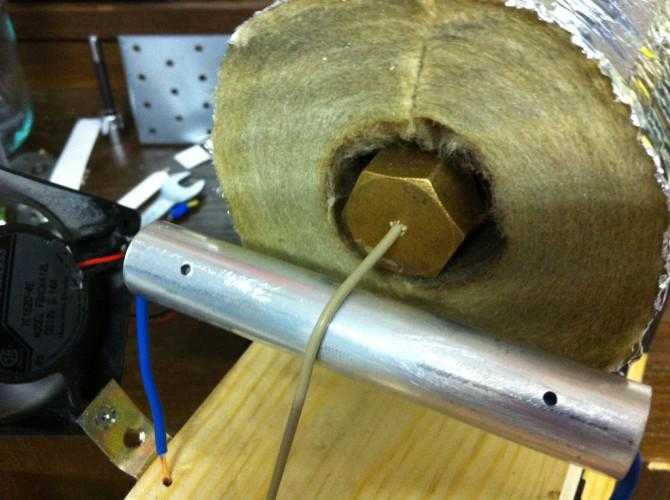 Shortly after that, the prices of printers went down a lot within that year as generic parts became more available.
I’d recommend for a decent Prusa style printer, you’ll be looking at at least $250 for parts for a super cheap but effective printer. If you’re wanting to make one that will have less headaches, then make that about $350-400 minimum. (I’ll explain why later on).
Second – Frame
What type of frame do you want to have?
What type of tools do you have?
I built my first frame out of Wood. I went with a softer hardwood. Poplar – It was easy to work with and solid.
The types of materials:
- Wood – Easy to shape and manipulate. Can be expensive for hardwood.
- Aluminum – Ready made t-slot rail Is fairly priced. Aluminum plate is usually expensive.
- Steel – Can be bought as angle iron and welded, or as threaded rod and secured with nuts, Very inexpensive.
Keep in mind the tools you have access to and what you’ll be able to work with.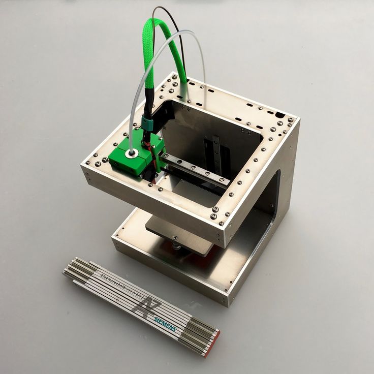
Third – Size
What size do you want to go for?
Where are you going to put it?
Size doesn’t always matter. It’s more logical to go with a size that is standardized rather than unusual sizes.
By far the most common size is a 200 x 200mm print area. The Z height varies but is typically also around 200mm as well. Some printers have a taller Z height, but that is up to you, the designer, to make that decision. It is a variable that isn’t quite standardized.
Fourth – Primary Electronics
Here is where choices get somewhat difficult.
Boards and mosfets
My first board was a Ramps 1.4 board with an Arduino Mega as the brains. I went the cheap route and got both of the parts from China off of Ebay. I had problems with the heat bed mosfet overheating and cutting out repeatedly. I even ordered a high power mosfet that worked for a little while, but eventually fried the board traces because it couldn’t handle the power. So I ordered a new board, and that one worked for a while, but the thermal sensor was an unusually small one that kept overheating. So I took the regular sized one off the old board, and soldered it into the new board along with the good mosfet. That worked for a while as well. I was afraid I was going to have problems with the board again, so I went with a relay to switch power on and off. That worked great for a while, but it was getting unusually hot, so I eventually went with a solid state relay.
TL;DR; Bought multiple cheap Ramps boards that ended up costing what the original was.
So I recommend getting authentic brains for your 3D printer at the bear minimum of genuine parts.
The Choices:
- Ramps 1.4 + Arduino Mega 2560 (most common)
- Smoothieboard
Ramps 1.4 + Arduino Mega 2560
Pros Ramps 1.4 + Arduino Mega 2560:
- Cheap
- Easy to use
- Easily modifiable
- Can use digital or analog drivers
- Widely available.
Cons Ramps 1.4 + Arduino Mega 2560:
- A lot of knockoffs out there, Often have weak mosfets that fail or overheat
- Will probably need cooling
- Bulky
Other:
- Uses Marlin or Repetier firmware
- Available from Ebay / Amazon
Smoothieboard
Pros Smoothieboard:
- Single Board
- Higher resolution
- Digital Drivers
- Packed with possibilities and very versatile
- Recommended by Thomas Sanladerer
Cons Smoothieboard:
- Higher price
Other:
- Uses Smoothie firmware (designed for the board)
- Available from Smoothieware.
 org
org
Various other boards
Rambo, Rumba, Melzi, Sanguinololu, and many others.
There are dozens of other boards out there to choose from, but the main two I focused on, I would recommend. Just remember, research your investment before purchasing.
Fifth – Power
What kind of power supply do you want to use?
There are two common types of power supplies available.
- Standalone raw 12v DC supply (common on commercial printers)
- Simple 12V only output (3 Sets typically), slim design.
Pros Standalone raw 12v DC supply:
- Simple 12v only output (3 Sets typically)
- slim design.
Cons Standalone raw 12v DC supply:
- No on/off switch (can be installed inline with the AC signal – electronics and soldering necessary)
- Max power seems to be around 360Watts.
Pros ATX power supply (PC supply):
- Automatic power on power off controllable by printer board
- Physical on/off switch(typically)
- Higher power
Cons ATX power supply (PC supply):
- Requires moderate modification (recommend upgrading wire directly off of circuit board – requires electronics knowledge and voids warranty)
I personally recommend going with an ATX supply because they are relatively cheap for a 500W PC power supply and can be easily switched on and off.
Sixth – Motors
Most printers use stepper motors that are called NEMA 17 motors. These will have to be the 4 wire variant.
Depending on the size of your printer, you might want to go with NEMA 15 or NEMA 23.
For your average size printer, a NEMA 17 will work just fine.
The first motors I bought were NEMA 15’s from China. They were used and really cheap. They worked great, except for the fact that they got really hot. Eventually the extruder motor failed and I had to replace it. So I went with a larger NEMA 17. It worked amazing. I didn’t have any more problems feeding filament or heating issues. The motor I got was from Stepper-Online off of Ebay. I bought two more after that for the X and Y. They are all still going strong and working great (still need to upgrade the Z motors). I also went with them again for my large printer build. 6 Total for X, Y, Zx2, E0, E1.
Seventh – Hotend
There are quite a few different types of hotends to choose from out there.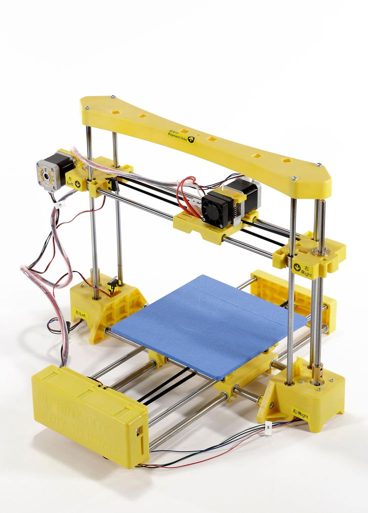
The most current common seems to be the E3D-V6.
I haven’t tried any others, so I don’t know what else to recommend or use. This style just works.
What I am currently using are E3D-V6 clones that I got off of Aliexpress from China. I haven’t seen any major problems like I’ve seen people post about on Reddit. Mine are slightly modified with 3mm throats with a 3mm O.D. x 2mm I.D. PTFE tube insert (cut from a length of stock I have, and I don’t plan on printing anything other than PLA with this particular printer – so no high temps). They very rarely ever have any clogging issues, and print just fine.
This is also a moral dilemma of quality over quantity. You can get cheap clones, or get quality parts from E3D themselves which also includes customer support. This is probably one of the parts you don’t want to go cheap on though, as it’s the heart of the machine. And they have gone down in price.
Eighth – To Bowden or not to Bowden
The next decision is whether you want to use direct drive or a bowden tube.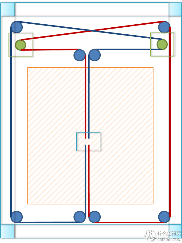 Let’s look at the differences.
Pros direct drive:
- Fast response to hotend
- Less chance of clogged nozzle
Cons direct drive:
- Weighs down hotend assembly causing more inertia and requiring more power to the axis
- Filament drag
Pros bowden:
- Lighter hotend allows faster printing speed
- less chance of drag from filament
Cons bowden:
- Sloppier hotend response
- Filament waste when fixing clog
I personally prefer Bowden designs because they are easier to use regarding extruder design and you never have to put much pressure on the hotend assembly.
Recently, there has been an invention that uses a direct drive bowden configuration. It has a regular bowden tube that has an extruder assembly on the hotend assembly. The hobbed mechanism is turned via a rotary cable from the stepper motor. The same type of cable that’s used on dremel tools or speedometer cables.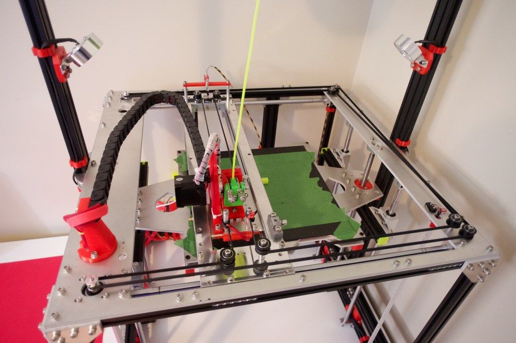 It’s just a smaller version meant to drive a worm gear on a drive gear.
Ninth – Linear Rails
Most commonly used for linear rails are 8mm steel rods. Usually they are hardened on the outside to prevent excessive wear. Along with those are LM8UU linear bearings. Eventually over time, these wear into the rods causing some slop and sticky spots. A cheap readily available alternative has yet to implemented, but there are other options.
This is one of the most important parts of the printer and requires a lot of decision making. Think about it several times, and always go back to it before finally deciding.
Lets look at all of the choices.
Pros rods with LMXUU Bearings (Metric Only):
- Very common and available (difficult in USA – has to be imported)
- easily sized to length
- Bearings are cheap if bought in bulk
- Great perpendicular stability.
Cons rods with LMXUU Bearings (Metric Only):
- Wear is a problem over time
- Difficult to buy in USA
Pros rods with Roller Bearings (Metric or SAE sizes):
- Size doesn’t matter
- Can use Standar SAE sizes instead of metric
- Easily sized to length
- Bearings are cheap if bought in bulk
Cons rods with Roller Bearings (Metric or SAE sizes):
- Complicated bearing assemblies requiring very tight tolerances
- Requires additional hardware that adds to cost
- Weak perpendicular stability
Pros rods with Bushings (Metric or SAE):
- Least expensive
- Readily available
Cons rods with Bushings (Metric or SAE):
- Needs regular cleaning and lubrication
- Limited smoothness in motion
- Can wear over time
Pros fixed Rods with Half LMXUU Bearings:
- Very precises movement
- Very smooth movement
Cons fixed Rods with Half LMXUU Bearings:
- Expensive
- Can wear over time
Pros flat Linear Rail Guide with Bearing Block:
- Very precise movement
- Very smooth movement
- Low wear
Cons flat Linear Rail Guide with Bearing Block:
- Very expensive
Pros Aluminum Rail with Roller Bearings:
- Aluminum is inexpensive
- ypically very straight.
Cons Aluminum Rail with Roller Bearings:
- Hardware can be expensive
I used 8mm rods with LM8UU bearings for my first printer. After a year, the rods have grooves from the bearings digging in to them. It still prints pretty decently, but they probably should be replaced.
My second large printer, I made my own roller bearings in 2 triangle formations about an inch and a half apart. They work surprisingly well and are very quiet. They took a lot of design time, and a lot of small bearings. They were 4x8x3mm(4mm Wide, 8mm diameter, and a 3mm hole) bearings. 6 per rod end x 4 = 24 bearings. On the hotend assembly, I used 12x – 3x8x4mm(I ordered the wrong ones and just used them anyway). These are all rolling on 12mm rods that are 600mm long. The Z-axis has 4 rods total with 24 – 5x14x5mm bearings.
In conclusion on linear rails, I’d recommend what you can afford, along with size. Standard sizes are a very limiting factor on pricing.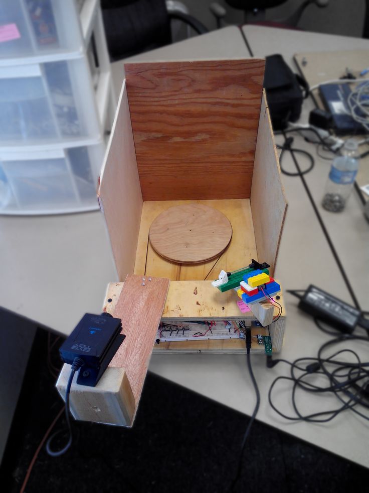 Decent rods are finally at a nice price now. Whatever you decide to choose, you’ll have to allow for tolerances. I’ll go through that later in an example.
Tenth – Belts
The standard for almost all 3D printers is the GT2 size belt. It’s commonly available in meter size lengths. Depending on the size of your printer, most meter size lengths will be more than enough.
The GT2 belt is easily cut with a knife, snips or any other sort of cutting tool with a sharp cutting surface.
If you are building a larger printer, it’s best to buy in bulk, as it is difficult to find lengths larger than 1 continuous meter.
Alternative to Belts – Lead Screws. Lead Screws can be used in place of belts, but the performance is generally not as fast as a belt driven system. They will still work quite well though.
Eleventh – Hardware (Nuts and Bolts….and misc)
The parts that hold everything together. The hardware. Once you have all of the ideas of what style of printer you want, the size and shape, etc…, you’ll want to start thinking about how you need to put everything together.
Before even designing all of the connecting joints together, it’s best to have an idea of what you’ll be working with.
Nuts and Bolts
For larger pieces that are structural, I recommend using at least M5 size bolts.
Depending on how thick the design parts are and how they are connected will determine the length you’ll need. I suggest at least 5mm on any part that is connect to another part. So if you have two connecting parts put flat together, there should be at least 10mm combined between the nut and bolt.
A good rule of thumb is to allow for at least the thickness of the bolt underneath the head and from the wall edge to the edge of the part. This will limit premature cracking and weakness.
Picking a head type
You can pick whatever type of bolt head you want. But I highly recommend using an allen wrench style bit head. Regardless of the head type, it’s the best solution for getting proper tension on the bolt.
For smaller parts, I like to use M3 size bolts of various lengths. It’s a fairly common size and pretty strong for their size.
Always get at least enough nuts to match the bolts, and always get extra bolts. It’s best to buy in bulk.
Washers
Washers are also important to get. These are needed for all sizes of bolts. They are not needed everywhere, but are needed in conjunction with bearings, and any other surfaces that need to move freely or need space to do so.
Bearings
The most common type of bearings used in 3D printers are 608ZZ. They are skate board bearings that are very common and thus inexpensive.
These can be used for belt idlers on the other end from the pulley. But I would recommend getting a couple 605ZZ or 685ZZbearings for each end. These are 5mm ID that fit M5 size.
You can also get idler pulleys that are bearings as well, the would work great too. They come with or without teeth in M5 sizes. They are quite a bit more expensive than regular bearings however.
Tools
A couple of different tools will be needed. The main tool will be a multi-bit set of small allen wrench pieces. Whatever you need to match the bolt head patterns. A small crescent wrench is highly recommended. (I can never seem to find mine)
A set of long needle nose pliers, regular pliers, and angled needle nose pliers.
Whatever tools you’ll think you’ll need.
Possibly a hacksaw to cut frame parts to length.
A vice to pressure fit parts together.
Twelfth – Secondary Electronics
Fans
Your hot end should come with a fan that will require a constant 12V power supply. You’ll need a second fan on the hot end assembly to cool filament as it prints. (primarily PLA)
There are two choices to get:
Blower style: A lot of airflow for great cooling, but noisy
Box style: Quiet, but usually lacks needed airflow without a voltage boost.
Another fan that I would recommend getting would be one for the Primary Electronics boards. This is useful for keeping the mosfets and poly fuses cool, as well as the stepper driver boards.
The only other optional fans that may be needed are for the stepper motors themselves. Sometimes they get hot and need to be cooled. Usually with a heatsink and fan connected. Making sure you have strong enough stepper motors to start with is recommended. They won’t need cooling.
Endstops
You’ll need to get at least 3 endstops. These are just microswitches like in a mouse button, but with a lever action. Quite often, these come soldered to a little board that plugs into the endstop location on the main board.
One for the Y-axis min point, one for the X-axis min point, and one for the Z min point. You can also attach another 3 to the max points, but is not necessary.
Instead of using a Z-axis endstop, you can use auto bed leveling. This will require a sensor to detect the distance of the hotend from the bed.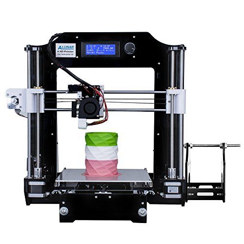
Auto-bed leveling is a rather advanced setup, and I recommend doing it later on when you are more experienced with the intricacies of the printer as a whole. You should concentrate on manual leveling to get that set up correctly first.
Power Switching
If you’re using a Ramps board, I highly suggest using a Relay or Mosfet transistor to switch the power on to the heated bed. The Ramps board doesn’t seem to handle the amperage very well and will get very hot and overheat the poly fuse, the mosfet on board, burn up the input power lead or blow a trace on the board itself.
Using a secondary switching device alleviates the stress that the Ramps board has to deal with. The temperature will fluctuate slightly more, but it is not extreme, only 1C or so.
I personally would recommend using a Solid State Relay rated at least 4 times what your bed will be drawing for Amperage. I have a 40A Relay and it gets very warm. One rated for more power will not get as hot.
You can also implement a Mosfet inline to do the switching from the main output from the main Mosfet.
Thirteenth – Bed Mount
No matter what type of printer you make, you’re going to have to have something that the bed will mount to. There are a number of different materials that you can use for the bed mount.
Most common is Aluminum because it is heat resistant and very rigid. Both great qualities.
Another common one is wood. It is simple and sturdy and resists heat as well.
I used wood at first on my first printer. It worked great for a while but was too flimsy. (I used too thin of a piece)
I later upgraded this to plexiglass that I got out of an old used LCD Monitor. I cut it down to size and drilled mounting holes that would fit 4mm/OD 3mm/ID PTFE tubing for the heated bed. I used M3 screws. The PTFE insulates any heat that would go into the plexiglass. To mount it to the bearing assembly, I just used regular bolts without insulation.
You can use any rigid material that will withstand heat and is not flexible.
Fourteenth – Heated Bed
If you’re going through the trouble of building your own printer, you should definitely use a heated bed.
The most common heated bed out there is the MK2A PCB bed It is Red and is usually around $15.00 or so.
The newer version is the aluminum version, the MK3. It is the same as far as wiring goes, but it is made of a non-flexible aluminum and seems very rigid. I have one of these for my next printer build, but have not tested it yet. I’ve only used the MK2A so far, and they seem to work well.
I would also recommend insulating the heated bed with something that can repel the heat underneath the bed to push it back up through the top instead of radiate out of the bottom.
There are several different types of materials you can use, from cork, forge insulation batting, to something that I use called aerogel. It’s a very good insulator that withstands extreme temperatures. It’s a little bit overkill, but it works well.
Fifteenth – Design the 3D printer
This is probably the most important and helpful step in the entire process.
Now that you’ve decided on what kind of printer you want to build. Build it virtually. Find out the exact dimensions of all of the components that you’re planning on using. Re-create those components and place them together. Not only is this great practice for modeling, it’s necessary so that you can make your 3D printed parts that you’ll need. They don’t have to be detailed down to internal component workings like bearings. Those can be just plain cylinders. But if you want to render it, then go for making them as detailed as possible. Place everything where it needs to be so you can see if your idea will work.
This is especially helpful if you don’t have a printer to begin with. You can give the files to someone to print for your or even order the parts to be printed. The only problem with this, is that sometimes parts need to be re-made and the time delay may be lengthy. Not every design works on the first try. That’s just part of the process.
Remember to try and make every 3D printed part design easily replaceable.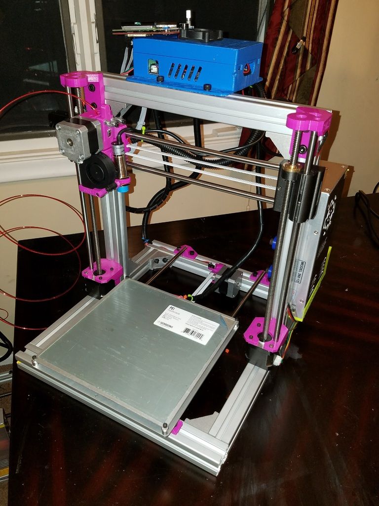 Also make them strong enough to withstand all of the different stresses that you anticipate. There are going to be parts that aren’t as strong as you anticipated. I’ve had to re-design several things. Notably, motor mounts, extruders, and anything that has a lot of torque.
This is probably a daunting task, but It can be a fun and educational experience. If you need a reference, I have a series of videos where I design a complete printer using Blender. You can find it here : 3D Printer Design Tutorials by inventimark.
(A few notes on the tutorial – I didn’t make the parts easily replaceable like I recommended, and I make a design change later in the video. I never did make this printer. It was just an educational modeling practice on an idea of designing a printer. After building my large printer (based on this design) I realized that I should have made some of the parts easily replaceable.)
Building the Prusa style printer
So, now we build.
The first thing you’ll want to do is put together the frame. Whichever design you go with, you’ll want to get the basic shape made.
Tighten everything down snug, but not to the final tightness.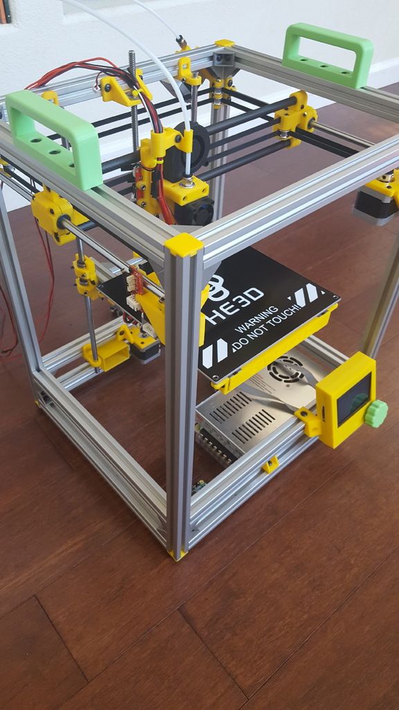 Once you get everything where it needs to be, then you can finally make everything set and even put some locktite on the bolts to make sure they don’t wiggle loose.
The next thing to move onto is getting the linear rails in place.
Before we put them on the printer, make sure that you have the appropriate bearings/bushings in place on each rod if you’re using those. Or if using the tri-bearings like I have, put the assembled bearing piece on.
Lets go over a detailed assembly of a Prusa style printer first.
So we have the frame assembled. I would suggest going with the Y-axis as the first part to put together.
Get the linear rails put together and in place on the frame.
Next you can install the Y carriage onto the bearings. Once you get that installed, you can install the bed mount onto the Y carriage. We will put the heated bed on as a last step.
For the X-axis, we can assemble everything that goes on it except for the hotend and motor.
Once the X-axis with carriage is put together, we can then attach it to the bearings and nut on the Z-axis.
Next, we install the linear rails for the Z-axis through the X-axis assembly and secure them into the frame.
Once we get these installed we can already tell that the firmness of the printer has increased by quite a bit.
Once we have these all together, we should have a bed the moves freely back and forth with barely any friction, an X-axis that moves back and forth freely as well without any friction, and the Z-axis should move up and down without any binding. The Z-axis may be difficult if you have the leadscrews in, which will be covered in a little bit.
If everything moves free without any friction, we can tighten down the frame completely. If it’s binding, you’ll need to adjust something, or tighten the frame to makes sure everything is moving in parallel.
After we have good movement all around, we can install the motors and belts.
First we want to mount all of the motors. The Y-axis motor should be positioned and secured fully with it’s pulley mounted on the shaft.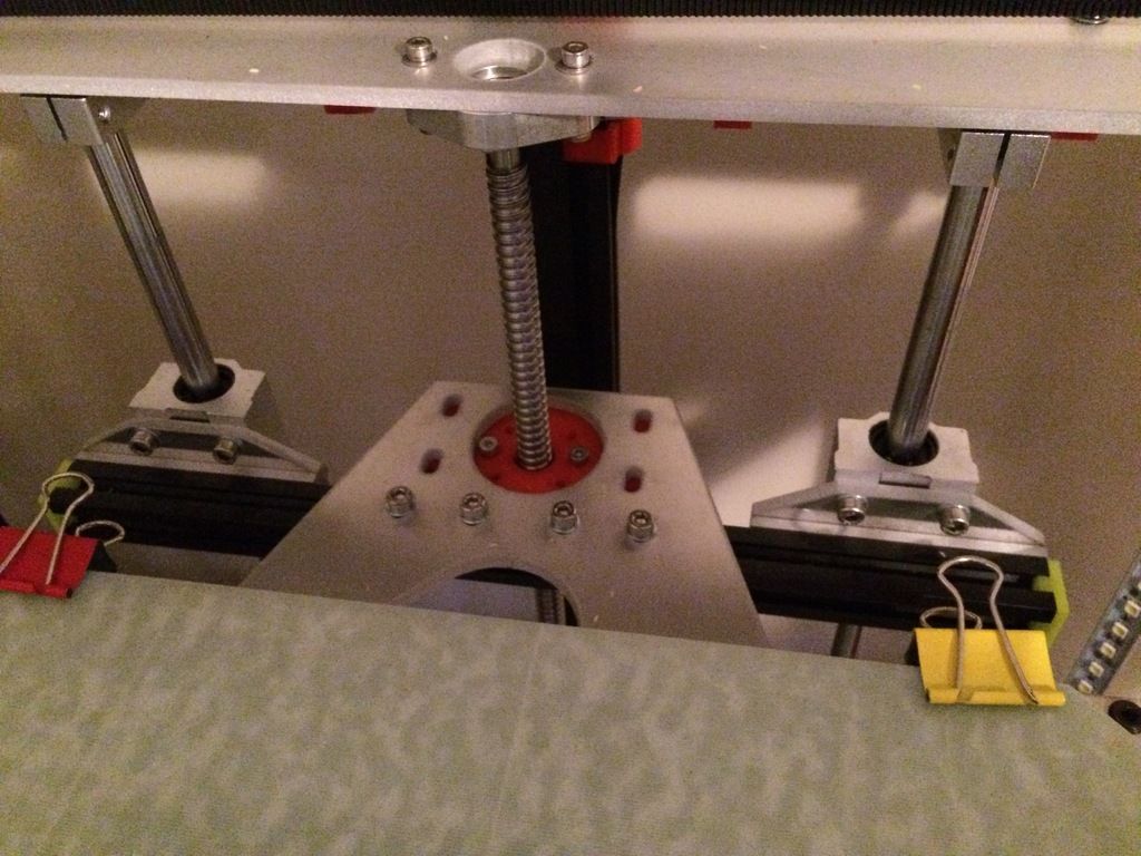 Make sure to tighten the set screws all the way. On the opposite end from the motor, we’ll need to mount the bearing assembly on the other side of the Y-axis.
Once we get that part put in, we can connect the belt. You’ll probably need to put the computer on it’s back. When tipping it, be careful to hold the bed so it doesn’t slam onto the work surface. First connect one end of the belt onto the Y carriage. Usually it’s connected around something round with the belt folded back onto itself with a zip tie to hold it tight against itself. Feed the belt around either the pulley or the bearing, and loop it around to the other side of the carriage making sure that the belt is not twisted. Secure the belt to the other side of the Y carriage. Loop it over itself and put a zip tie on it. (Do not tighten the zip tie all the way down yet). Get the zip tie slightly tight and use two pairs of pliers to pull the belt as tight as you can get it. (Have someone help you if you can). And then Pull the zip tie tight while the belt is under tension.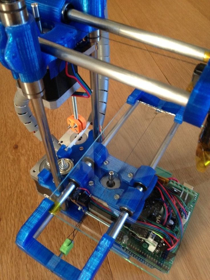 If you’ve designed the printer well, there should be a way to tension the belt that will not allow for any springiness. I use M3 screws that can tighten the belt as much as needed. The belt should be taught, but not so much that it restricts movement.
Put the printer back into it’s normal orientation and test the movement of the Y-axis. It should move smoothly, but have resistance from the motor turning.
Next we’ll get the Z-axis up and running. Install the motors first. Then install the couplers for the leadscrews. If you don’t have the leadscrews installed yet, now is the time. Feed them through the X-axis and connect them to the couplers. Now you can tighten the set screws on the coupler and make sure they are all tightened. You should be able to turn the leadscrews together and the X-axis should move up and down smoothly. Move the Leadscrews so the X-axis is in a comfortable position to work on.
Now for the X-Axis Belt. First install the Motor and pulley like on the Y-axis. Then the bearing on the other side of the X-axis (You may have already done this). Now do the same thing you did with the Y carriage and get the belt into place. It should have the same feel of movement as the Y-axis. Smooth but slightly resistant from the motor.
We can now install the hotend into the X-axis carriage. Make sure it is fully assembled and is ready to be put in. Once you get it in, you can then install the blower fan for the prints. (the hotend should already have it’s fan installed) If you’re using direct drive, now is also a good time to install the extruder assembly onto the x-carriage as well. If using a bowden style, this can be done later.
Next we can wire all of the endstops and position them so that they work when whatever axis you are working on is at it’s end travel. When looking at the front of the printer, the X-axis endstop should be installed on the right side. The Y-axis endstop should be installed on the back of the printer, and the Z-axis endstop should be installed on the bottom of the Z-axis.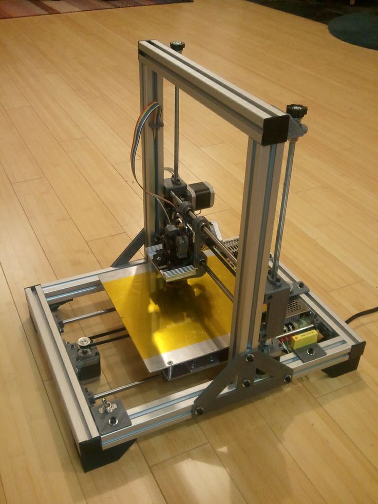
If you’re going to use a bowden setup, now is a good time to assemble the extruder and mount it to the frame with everything installed including the motor, just not the bowden tube.
Now’s a good time to route all of the wires to where you will be mounting the main electronics board.
It would be a good time to mount the main board as well. (don’t fully mount it if your printer isn’t nearby the computer with the firmware on it. This is because you’ll likely be making changes to the Arduino Mega or other board and uploading firmware regularly. You’ll only finally attach it when your final firmware is set)
Here we can route all of the wires so that there isn’t any crosstalk from wires running parallel. Some places this is unavoidable like in the hotend, There is a mesh tubing wrap that I would recommend getting that works great to wrap around wires. Using this on the hotend wires will keep them from being to close but keep them in the same bundle.
You can now connect all of the wires to the mainboard. Making sure to orient everything in the correct order.
One of the last things before connecting power is installing the hot bed.
First thing we need to do is wire up the hot bed with appropriate wires. Attach the thermistor to the bottom of the board through the hole in the middle. If you’re going to put the insulation on the bed, now is the time to do it. I have mine just sitting on the bed mount on my small printer. Once you get that done, you can then mount the bed to the bed mount. This is usually done with springs inbetween the two with bolts through both boards and a nut on the other end. You can put them in any orientation you like, but I recommend going from the top. You can hot glue or locktite the bolts to the hot bed on top. To adjust it, you just turn the bolts on the bottom to adjust the levelness of the bed. Now wire the bed to the main board and through the relay. Adjust the bed height to be as level as you feel it can be, with enough room on each corner to loosen or tighten each one a certain amount.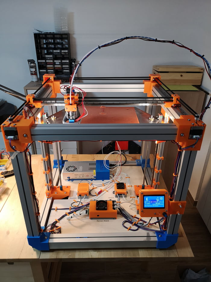 Now you can put the glass on the bed. I use simple paper clamps to clamp it to the bed on all 4 corners.
Now we can adjust the Z endstop so that the nozzle almost touches the glass and the endstop clicks. It shouldn’t be touching the glass at all. The endstop for the Z-axis should be easily adjustable with a screw of some sort. Jump ahead to the last segment to get to printing!
Building the Ultimaker / Darwin style printer
Putting this printer together is quite a bit different than the standard i3 Style printer… so lets start.
After the frame is together, the first thing we want to do is assemble the X and Y-axis assembly.
Start out with the two central rods and connect them to the XY carriage. The carriage should have the bearings already put into them. Once we have these together, we can test the movement by grabbing the end of each rod in either hand and moving your hands together and apart, the carriage should move forward and backwards with little resistance in a fluid motion.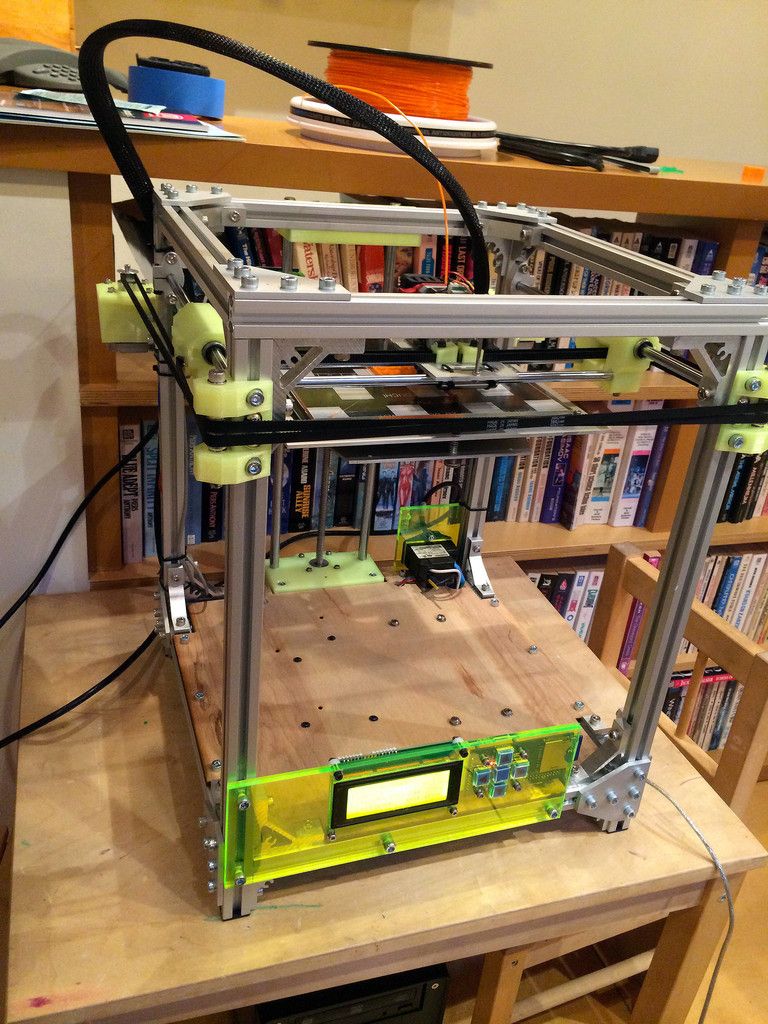
Now that we have that together, it’s time to put the bearing assemblies at the ends of each rod.
Once those are all in place, take one of the corner rod mounts and put one rod into it. Put one end of the bearing assemblies over the rod from the center carriage assembly making sure that it’s the rod that lines up properly with that rail.
Next, take another rod and put the rod through the perpendicular bearing assemble and connect the rod to that same corner.
Now we can connect the next two corner mounts. Placing the next rod through end bearing assembly of the central part into the adjacent corner. Do this again for the other corner mount.
The last part of this assembly is the trickiest. We have to put the final corner mount onto the rods. This may involve some uncomfortable twisting of everything, but it should go together without too much hassle, just don’t break anything!
Once we have all of this together, we can test it out by manually pushing the carriage around in a circle and all around to see if it moves smoothly.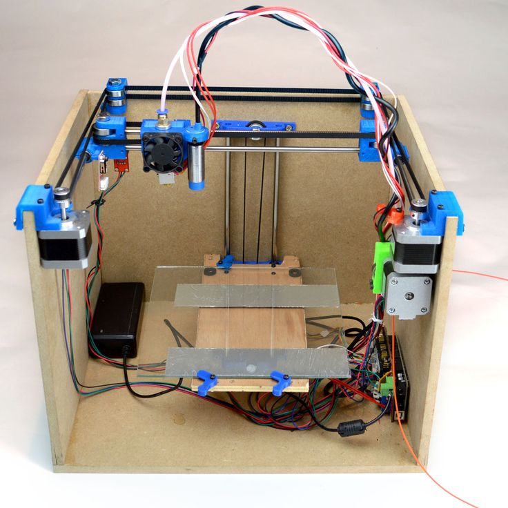 It will be somewhat floppy, so be careful. If it doesn’t move smoothly, then it’s time to troubleshoot.
Now we can mount this entire assembly to the frame. Once secured to the frame, it should be very sturdy and move with minimal resistance.
We can mount the Z-axis rods with the bottom motor mount and top Z-axis mounts, making sure to have the bearings in place before mounting the rods. (otherwise you’ll have to take it apart again)
Once we have the rods in place, we can attach the bed mount to the bearings. After we get that done, the bed assembly should move up and down freely without any resistance.
The next step is attaching the motors to the XY assembly.
Depending on how you have it set up, the motors should be connected with the pulleys and set screws secured.
Now we can connect the X and Y rail rods. These make sure that both sides of each axis move together without any deflection. These should have pulleys on both ends between the frames, as well as another pulley for each motor.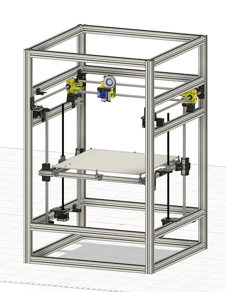 Make sure the set screws are in tight. Also connect the bearings at the opposite ends of the pulleys.
You can now connect the loop pulleys from the motors to the pulleys on the rods. Some sort of tensioning should be implemented on the loop belts to keep them taught at all times. I use a roller bearing, but you can design it so the motors move to keep the tension.
Now we can connect the belts. There will be four of them. Two for each axis.
Start out with the belt connected to the bearing assembly. Usually the belt connected around something round with the belt folded back onto itself with a zip tie to hold it tight against itself. Feed the belt around the pulley or the bearing, and loop it around to the other side of the bearing assembly to complete the loop, making sure that the belt is not twisted. Secure the belt to the other side of the rod bearing assembly. Loop it over itself and put a zip tie on it. (Do not tighten the zip tie all the way down yet). Get the zip tie slightly tight and use two pairs of pliers to pull the belt as tight as you can get it. (Have someone help you if you can). And then Pull the zip tie tight while the belt is under tension. If you’ve designed the printer well, there should be a way to tension the belt that will not allow for any springiness. I use M3 screws that can tighten the belt as much as needed. The belt should be taught, but not so much that it restricts movement.
Repeat this for the other 3 belt loops.
Now that all the belts are on, play around with the XY carriage and it should move with resistance from the motors without sticking anywhere. If it does, you’ll need to adjust the tension and equalize it.
We can now connect the Z motors to the frame/motor mounts on the bottom. Once connected, we can connect the coupler to the motors and feed the leadscrews down through the nut on the bed mount. Tighten the set screws and secure the leadscrews and motor shaft so they move together.
If you haven’t yet, now is a good time to mount the bed mount. Secure it to the bearings and leadscrew nuts.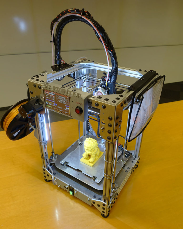 The bed should move up and down by turning the rod(s). If using more than one rod, try to get them as level as you can so that they run in parallel and the bed is flat.
Next we can wire all of the endstops and position them so that they work when whatever axis you are working on is at it’s end travel. When looking at the front of the printer, the X-axis endstop should be installed on the right side. The Y-axis endstop should be installed on the back of the printer, and the Z-axis endstop should be installed anywhere on the frame or mounts where the endstop will be activated when the bed is up the highest right before the bed will touch the nozzles with the glass on it. You can do this later if needed, once you have everything installed.
We can now install the hotend(s) into the XY carriage. Make sure it is fully assembled and is ready to be put in. Once you get it in, you can then install the blower fan for the prints.(the hotend should already have it’s fan installed) If you’re using direct drive, now is also a good time to install the extruder assembly onto the carriage as well. If you’re going to use a bowden setup, now is a good time to assemble the extruder and mount it to the frame with everything installed including the motor, just not the bowden tube.
Now’s a good time to route all of the wires to where you will be mounting the main electronics board.
It would be a good time to mount the main board as well. (don’t fully mount it if your printer isn’t nearby the computer with the firmware on it. This is because you’ll likely be making changes to the Arduino Mega or other board and uploading firmware regularly. You’ll only finally attach it when your final firmware is set)
Here we can route all of the wires so that there isn’t any crosstalk from wires running parallel. Some places this is unavoidable like in the hotend, There is a mesh tubing wrap that I would recommend getting that works great to wrap around wires. Using this on the hotend wires will keep them from being to close but keep them in the same bundle.
You can now connect all of the wires to the mainboard.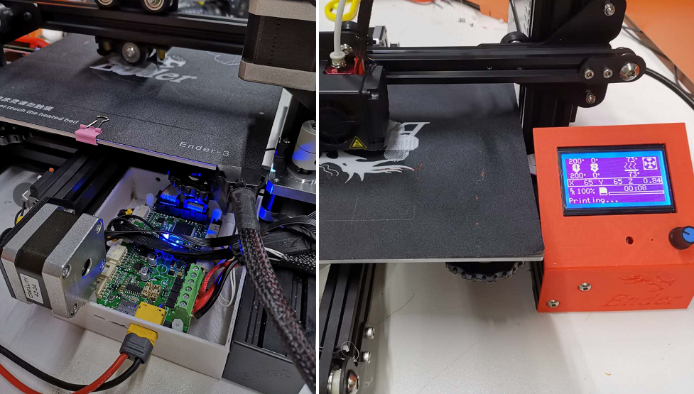 Making sure to orient everything in the correct order.
One of the last things before connecting power is installing the hot bed.
First thing we need to do is wire up the hot bed with appropriate wires. Attach the thermistor to the bottom of the board through the hole in the middle. If you’re going to put the insulation on the bed, now is the time to do it. I have mine just sitting on the bed mount on my small printer. Once you get that done, you can then mount the bed to the bed mount. This is usually done with springs in between the two with bolts through both boards and a nut on the other end. You can put them in any orientation you like, but I recommend going from the top. You can hot glue or locktite the bolts to the hot bed on top. To adjust it, you just turn the bolts on the bottom to adjust the levelness of the bed. Now wire the bed to the main board and through the relay. Adjust the bed height to be as level as you feel it can be, with enough room on each corner to loosen or tighten each one a certain amount.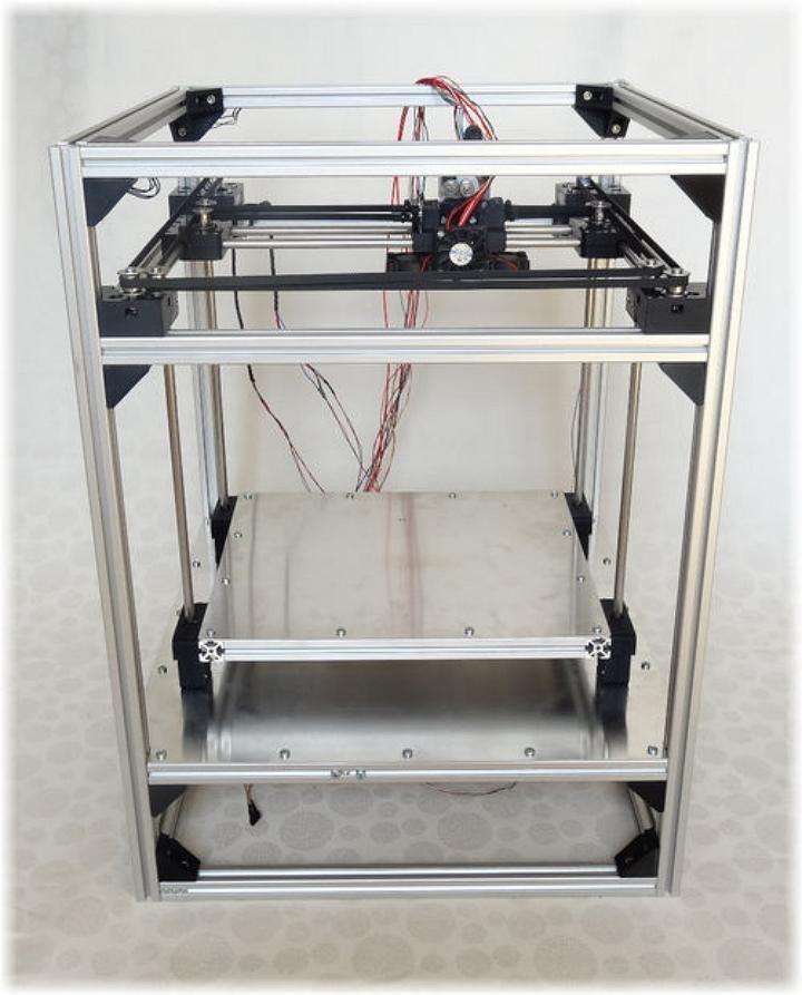 Now you can put the glass on the bed. I use simple paper clamps to clamp it to the bed on all 4 corners.
Now we can adjust the Z endstop so that the nozzle almost touches the glass and the endstop clicks. It shouldn’t be touching the glass at all. The endstop for the Z-axis should be easily adjustable with a screw of some sort. On to printing!
Your First Print
We’ve got it all together, now what?
With everything wired up and connected, we can now connect power and turn the printer on. Without connecting the printer to a computer yet.
If there is no blue smoke or sparks, and the main fans come on, then we have a success.
With it working, we can now connect it to the computer.
With your software open and the printer connected, the first thing to try to do is move the axis to check and see if they are moving correctly.
First try the Y-axis and see if it will home to the 0 location and stop with the endstop. Be ready to press the emergency stop in software or disconnect power if something happens.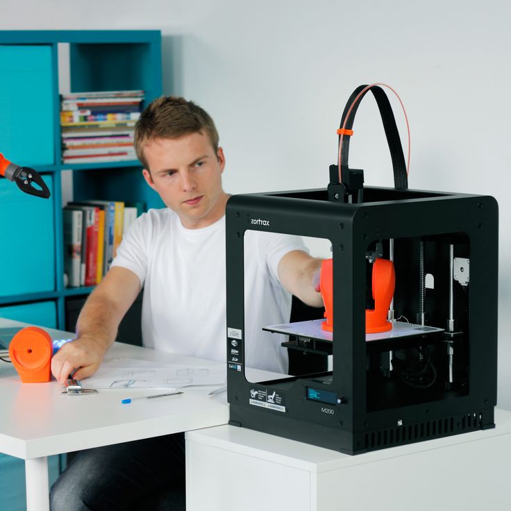
If it homes correctly, great! If not, time to troubleshoot.
Next test the X -axis and see if that works. Same as the Y-axis.
Now to see if the Z-axis works and homes to the correct point. First, we need to get the X-axis level. A good way to do this, is to raise the X-axis all the way to the top and let it top out and straighten itself out. You can move one side by hand if needed to get it level. Then home the Z-axis. It should stop where you set the hotend, right above the glass but not touching. (especially important to be ready to cut power with this test)
If all of those are working, we can now go on to test the function of hotend and the heated bed.
Set the initial heat for the hotend to something around 180 or so, just to see if it warms up correctly. This shouldn’t take very long at all. Hotends usually heat up very well. Now is a great time to tighten the nozzle and make sure everything is tight as can be without breaking it. Also test the heated bed, something around 60C should be good.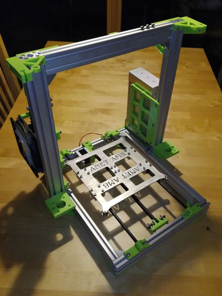 If these don’t work or there is an error, then it’s time to troubleshoot. Otherwise, it’s time to level the bed and test a print!
Now we know everything is working like it should be, then we can now level the bed.
Home all of the axis and turn the printer off and let it cool down.
Bed leveling
Now we can level the bed, making sure that there is only about a paper’s width between the hotend and the glass on all 4 corners. Adjusting each nut on the bottom until the paper barely grabs. Once everything appears to be level, go around and check each corner again. Repeat this process until you are 100% sure that every corner is just right. This is when we can put Loctite on the leveling nuts to keep them in place. We shouldn’t have to adjust the bed level again. (At least in theory or we screw something up – it happens)
Now we can turn on the printer, and load filament. Set the hotend to around 200C. Usually you’ll want to start off with PLA for a first time set up as it’s the easiest.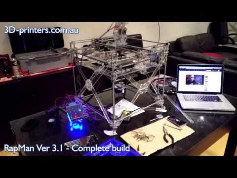 If you have a bowden tube setup, now is a good time to connect the tube. Load the filament after the hotend is at temp. With a bowden, you can turn the gear and manually feed the filament through the hotend, it should ooze out at a steady rate with little resistance. With a direct drive, you should be able to release tension on the tensioner and directly push the filament through. If this isn’t working, you’ll need to troubleshoot the problem.
With everything loaded, we can now try out our first print….. After we figure out what we’re going to do for bed adhesion.
I first started with Wood Glue for adhesion, but now I just use fingernail polish remover. Not pure acetone, but just plain cheap fingernail polish remover. It works great on glass with PLA. Others like to use build tack, pei, hairspray, pva, gluestick, or blue painters tape.
Finally, we can load a print and test everything out. If you’ve done the calculations correctly and put the correct steps per mm into the firmware, everything should roughly print correctly.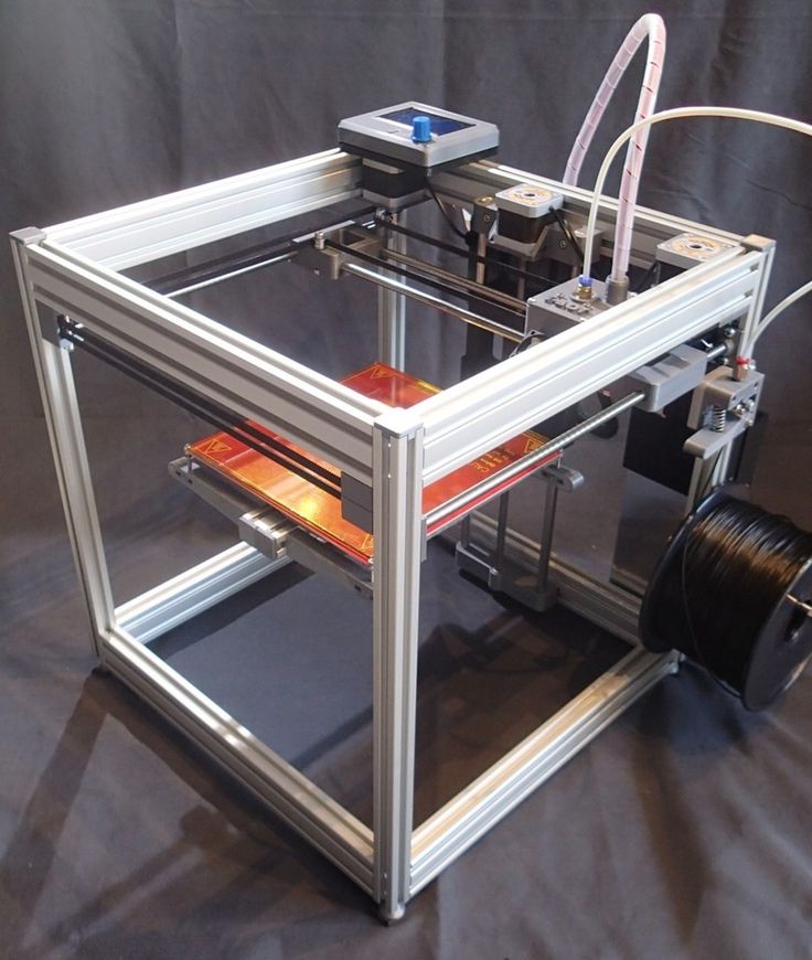 I recommend the 20mm cube for a first print, it’s simple and is a good basic measurement test.
Click print and see what happens. If it prints at all, then all that is left that is needed, is calibration, and the frustratingly fun part of 3D printing. More calibration and a million Benchy prints… j/k about the Benchies… but it happens…. Print on and have fun!
Thanks for checking this out.
Best of luck!
Building a home 3D printer with your own hands: recommendations from personal experience
3D printing and assembly of 3D printers is my hobby and passion. Here I will not share detailed diagrams and drawings, there are more than enough of them on specialized resources. The main goal of this material is to tell you where to start, where to dig and how to avoid mistakes in the process of assembling a home 3D printer. Perhaps one of the readers will be inspired by applied engineering achievements.
Why do you need a 3D printer? Use cases
I first came across the idea of 3D printing back in the 90s when I was watching the Star Trek series. I remember how impressed I was by the moment when the heroes of the cult series printed the things they needed during their journey right on board their starship. They printed anything: from shoes to tools. I thought it would be great someday to have such a thing too. Then it all seemed something incredible. Outside the window are the gloomy 90s, and the Nokia with a monochrome screen was the pinnacle of progress, accessible only to a select few.
Years passed, everything changed. Around 2010, the first working models of 3D printers began to appear on sale. Yesterday's fantasy has become a reality. However, the cost of such solutions, to put it mildly, discouraged. But the IT industry would not be itself without an inquisitive community, where there is an active exchange of knowledge and experience and who just let them dig into the brains and giblets of new hardware and software. So, drawings and diagrams of printers began to surface more and more often on the Web. Today, the most informative and voluminous resource on the topic of assembling 3D printers is RepRap - this is a huge knowledge base that contains detailed guides for creating a wide variety of models of these machines.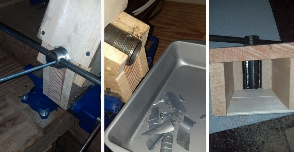
I assembled the first printer about five years ago. My personal motivation to build my own device is quite prosaic and based on several factors. Firstly, there was an opportunity to try to realize the old dream of having your own device, inspired by a fantasy series. The second factor is that sometimes it was necessary to repair some household items (for example, a baby stroller, car elements, household appliances and other small things), but the necessary parts could not be found. Well, the third aspect of the application is "near-working". On the printer, I make cases for various IoT devices that I assemble at home.
Agree, it is better to place your device based on Raspberry Pi or Arduino in an aesthetically pleasing "body", which is not a shame to put in an apartment or take to the office, than to organize components, for example, in a plastic bowl for food. And yes, you can print parts to build other printers :)
There are a lot of scenarios for using 3D printers.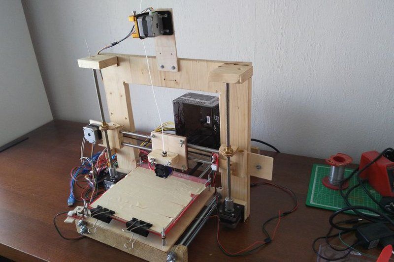 I think everyone can find something of their own.
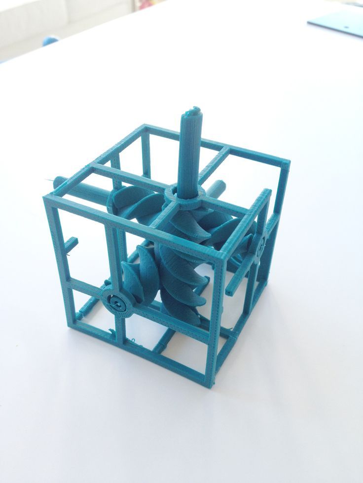
A complex part in terms of drawing that I printed on my printer. Yes, it's just a figurine, but it has many small elements
Ready solution vs custom assembly
When a technology has been tested, its value in the market decreases markedly. The same thing happened in the world of 3D printers. If earlier a ready-made solution cost simply sky-high money, then today acquiring such a machine is more humane for the wallet, but nevertheless not the most affordable for an enthusiast. There are a number of solutions already assembled and ready for home use on the market, their price range ranges from $500-700 (not the best options) to infinity (adequate solutions start from a price tag of about $1000). Yes, there are options for $150, but we, for understandable, I hope, reasons, will not dwell on them.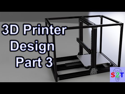
In short, there are three cases to consider a finished assembly:
- when you plan to print not much and rarely;
- when print accuracy is critical;
- you need to print molds for mass production of parts.
There are several obvious advantages to self-assembly. The first and most important is cost. Buying all the necessary components will cost you a maximum of a couple of hundred dollars. In return, you will receive a complete 3D printing solution with the quality of manufactured products acceptable for domestic needs. The second advantage is that by assembling the printer yourself, you will understand the principles of its design and operation. Believe me, this knowledge will be useful to you during the operation of even an expensive ready-made solution - any 3D printer needs to be serviced regularly, and it can be difficult to do this without understanding the basics.
The main disadvantage of assembly is the need for a large amount of time. I spent about 150 hours on my first build.
What you need to assemble the printer yourself
The most important thing here is the presence of desire. As for any special skills, then, by and large, in order to assemble your first printer, the ability to solder or write code is not critical. Of course, understanding the basics of radio electronics and basic skills in the field of mechanics (that is, "straight hands") will greatly simplify the task and reduce the amount of time that needs to be spent on assembly.
Also, to start we need a mandatory set of parts:
- Extruder is the element that is directly responsible for printing, the print head. There are many options on the market, but for a budget build, I recommend the MK8. Of the minuses: it will not be possible to print with plastics that require high temperatures, there is noticeable overheating during intensive work, which can damage the element. If the budget allows, then you can look at MK10 - all the minuses are taken into account there.

- Processor board. The familiar Arduino Mega is well suited. I didn't notice any downsides to this solution, but you can spend a couple of dollars more and get something more powerful, with a reserve for the future.
- Control board. I'm using RAMPS 1.4 which works great with the Arduino Mega. A more expensive but more reliable board is Shield, which already combines a processor board and a control board. In modern realities, I recommend paying attention to it. In addition to it, you need to purchase at least 5 microstep stepper motor controllers, for example - A4988. And it's better to have a couple of these in stock for replacement.
- Heated table. This is the part where the printed element will be located. Heating is necessary due to the fact that most plastics will not adhere to a cold surface. For example, for printing with PLA plastic, the required surface temperature of the table is 60-80°C, for ABS - 110-130°C, and for polycarbonate it will be even higher
There are also two options for choosing a table - cheaper and more expensive. Cheaper options are essentially printed circuit boards with preheated wiring. To operate on this type of table, you will need to put borosilicate glass, which will scratch and crack during operation. Therefore, the best solution is an aluminum table.
 - Stepper motors. Most models, including the i2 and i3, use NEMA 17 size motors, two for the Z axis and one each for the X and Y axes. Finished extruders usually come with their own stepper motor. It is better to take powerful motors with a current in the motor winding of 1A or more, so that there is enough power to lift the extruder and print without skipping steps at high speed.
- Basic set of plastic fasteners.
- Belt and gears to drive it.
Examples of elements appearance: 1) MK8 extruder; 2) Arduino processor board; 3) RAMPS control board; 4) motor controllers; 5) aluminum heated table; 6) NEMA 17 stepper motor; 7) a set of plastic fasteners; 8) drive gears; 9) drive belt
This is a list of items to be purchased.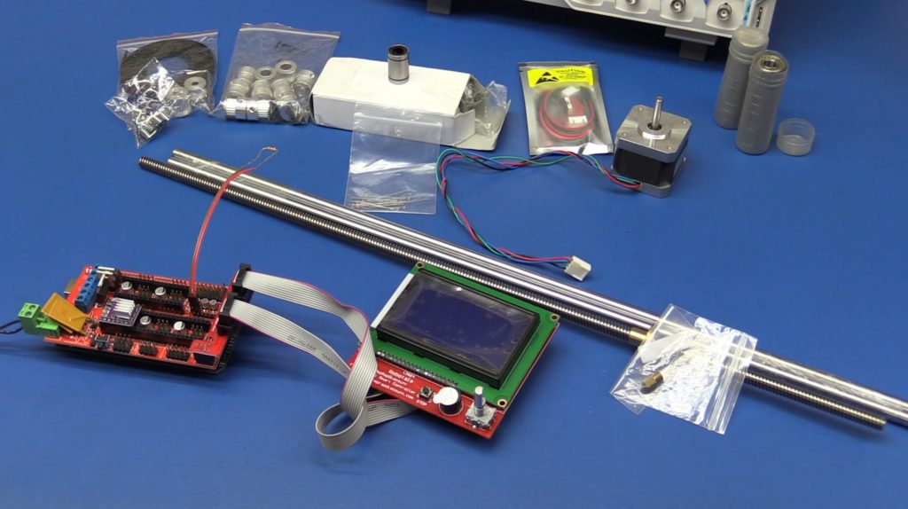 Hardcore users can assemble some of them themselves, but for beginners, I strongly recommend purchasing ready-made solutions.
Yes, you will also need various small things (studs, bearings, nuts, bolts, washers ...) to assemble the case. In practice, it turned out that using a standard m8 stud leads to low printing accuracy on the Z axis. I would recommend immediately replacing it with a trapezoid of the same size.
M8 trapezoid stud for Z axis, which will save you a lot of time and nerves. Available for order on all major online platforms
You also need to purchase customized plastic parts for the X axis, such as these from the MendelMax retrofit kit.
Most parts available at your local hardware store. On RepRap you can find a complete list of necessary little things with all sizes and patterns. The kit you need will depend on the choice of platform (we'll talk about platforms later).
What's the price
Before delving into some aspects of the assembly, let's figure out how much such entertainment will cost for your wallet. Below is a list of parts required for purchase with an average price.
Platform selection
The community has already developed a number of different platforms for assembling printers - the most optimal case designs and the location of the main elements, so you do not have to reinvent the wheel.
i2 and i3 are key platforms for self-assembly printer enclosures. There are also many modifications of them with various improvements, but for beginners, these two classic platforms should be considered, since they do not require special skills and fine-tuning.
Actually, illustration of platforms: 1) i2 platform; 2) i3 platform
On the plus side of i2: it has a more reliable and stable design, although it is a little more difficult to assemble; more opportunities for further customization.
The i3 variant requires more special plastic parts to be purchased separately and has a slow print speed. However, it is easier to assemble and maintain, and has a more aesthetically pleasing appearance.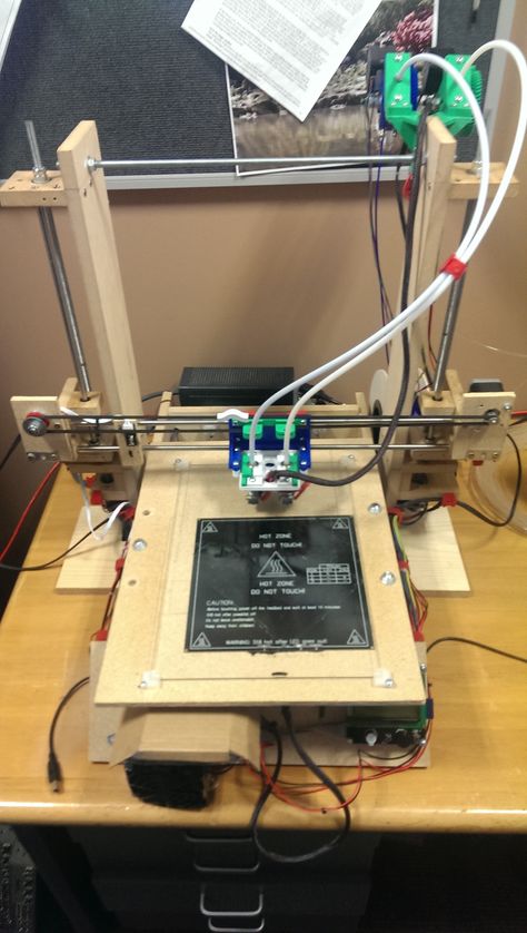 You will have to pay for simplicity with the quality of printed parts - the body has less stability than i2, which can affect print accuracy.
Personally, I started my experiments in assembling printers from the i2 platform. She will be discussed further.
Assembly steps, challenges and improvements
In this block, I will only touch on the key assembly steps using the i2 platform as an example. Full step by step instructions can be found here.
The general scheme of all the main components looks something like this. There is nothing particularly complicated here:
I also recommend adding a display to your design. Yes, you can easily do without this element when performing operations on a PC, but it will be much more convenient to work with the printer this way.
Understanding how all components will be connected, let's move on to the mechanical part, where we have two main elements - a frame and a coordinate machine.
Assembling the frame
Detailed frame assembly instructions are available on RepRap.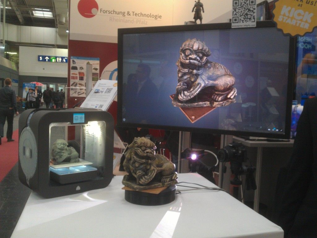 Of the important nuances - you will need a set of plastic parts (I already talked about this above, but I'd better repeat it), which you can either purchase separately or ask your comrades who already have a 3D printer to print.
The frame of the i2 is quite stable thanks to its trapezoid shape.
This is how the frame looks like with parts already partially installed. For greater rigidity, I reinforced the structure with plywood sheets
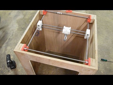
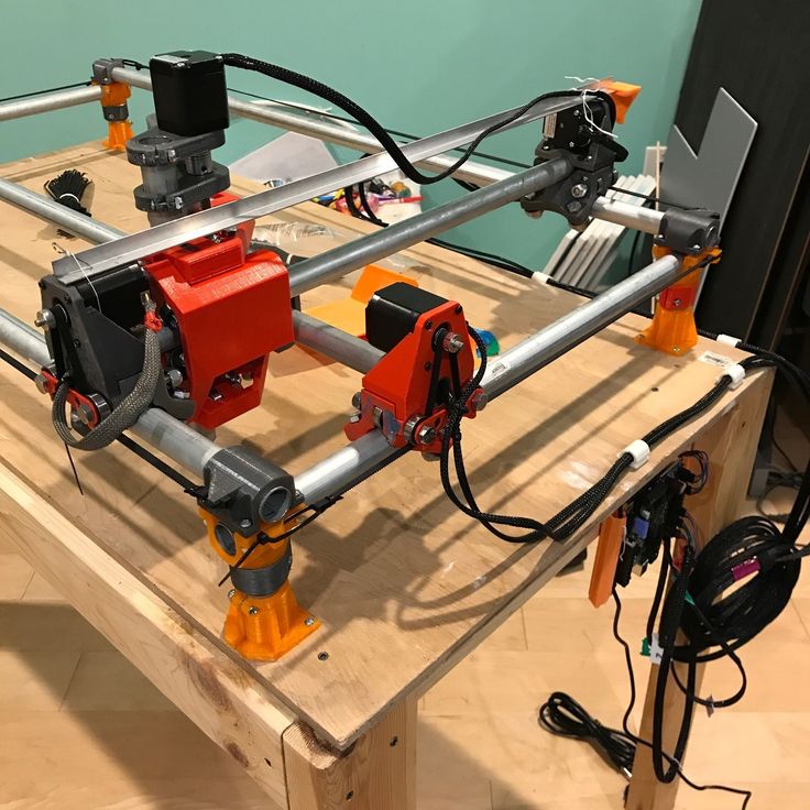
Coordinate machine
An extruder is attached to this part. The stepper motors shown in the diagram above are responsible for its movement. After installation, calibration is required along all major axes.
Important - you will need to purchase (or make your own) a carriage for moving the extruder and a mount for the drive belt. Drive belt I recommend GT2.
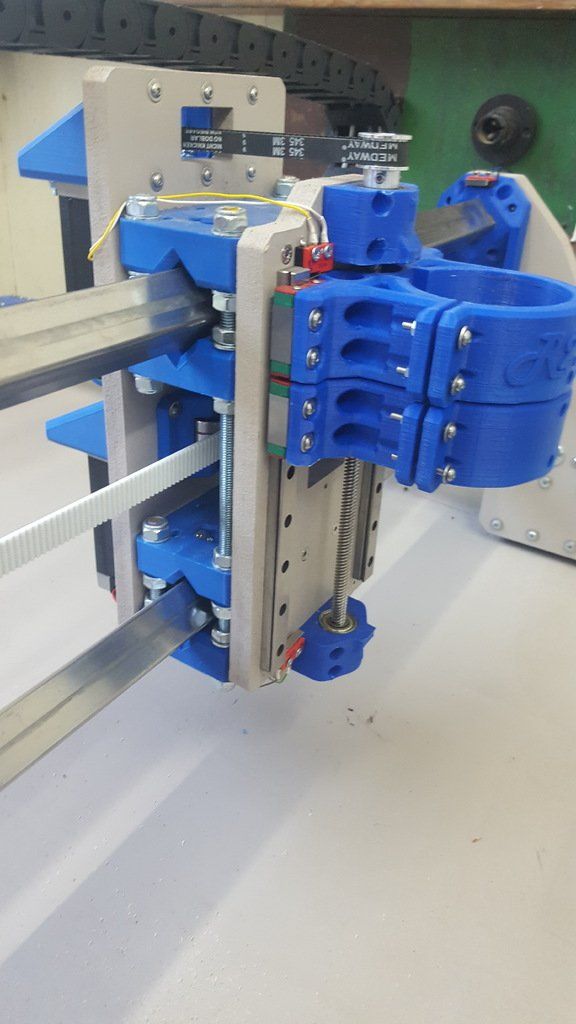
The carriage printed by the printer from the previous picture after it has been assembled.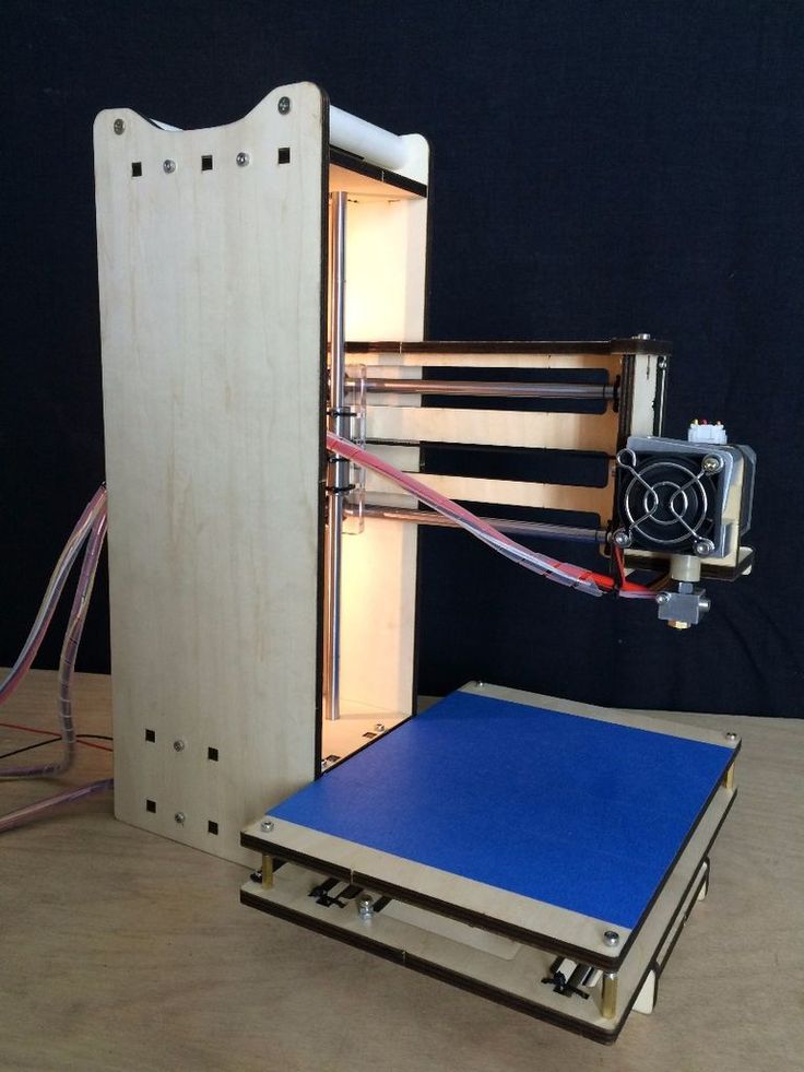 The part already has LM8UU bearings for guides and belt mount (top)
Calibration and adjustment
So, we completed the assembly process (as I said, it took me 150 hours) - the frame was assembled, the machine was installed. Now another important step is the calibration of this very machine and extruder. Here, too, there are small subtleties.
Setting up the machine
I recommend calibrating the machine with an electronic caliper. Do not be stingy with its purchase - you will save a lot of time and nerves in the process.
The screenshot below shows the correct constants for the Marlin firmware, which must be selected in order to set the correct number of steps per unit of measure. We calculate the coefficient, multiply it, substitute it into the firmware, and then upload it to the board.
Marlin 9 firmware constants0022
For high-quality calibration, I recommend relying on larger numbers in measurements - take not 1-1.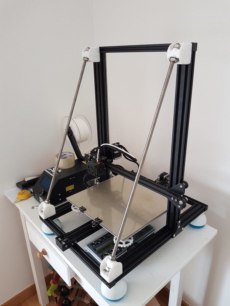 5 cm, but about 10. So the error will be more noticeable, and it will become easier to correct it.
Calibrating the extruder
When the frame is assembled, the machine is calibrated, we start setting up the extruder. Here, too, everything is not so simple. The main task of this operation is to correctly adjust the supply of plastic.
If underfeeding, the printed test item will have noticeable gaps, like test die 1. Conversely, the result will look bloated if plastic is overfed (dice 2)
Getting Started Printing
It remains for us to run some CAD or download ready-made .stl, which describe the structure of the printed material. Next, this structure needs to be converted into a set of commands understandable to our printer. For this I use the Slicer program. It also needs to be set up correctly - specify the temperature, the size of the extruder nozzle. After that, the data can be sent to the printer.
Slicer interface
As a raw material for printing, I recommend starting with regular ABS plastic - it is quite strong, products made from it are durable, and it does not require high temperatures to work with.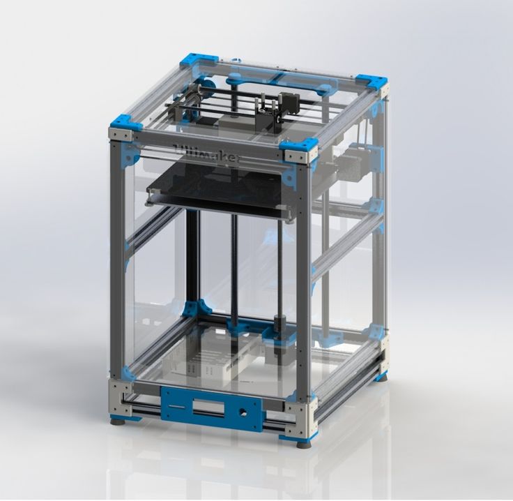 For comfortable printing with ABS plastic, the table must be heated to a temperature of 110-130 ° C, and the extruder nozzle - within 230-260 ° C.
Some important details. Before printing, calibrate the machine along the Z axis. The extruder nozzle should be approximately half a millimeter from the table and ride along it without distortion. For this calibration, a regular sheet of A4 paper inserted between the nozzle and the surface of the heated table is best suited. If the sheet can be moved with little effort, the calibration is correct.
Another thing to keep in mind is the surface treatment of the heated table. Usually, before printing, the surface of the table is covered with something that hot plastic sticks to well. For ABS plastic, this can be, for example, Kapton tape. The disadvantage of adhesive tape is the need to re-glue it after several printing cycles. In addition, you will have to literally tear off the adhering part from it. All this, believe me, takes a lot of time.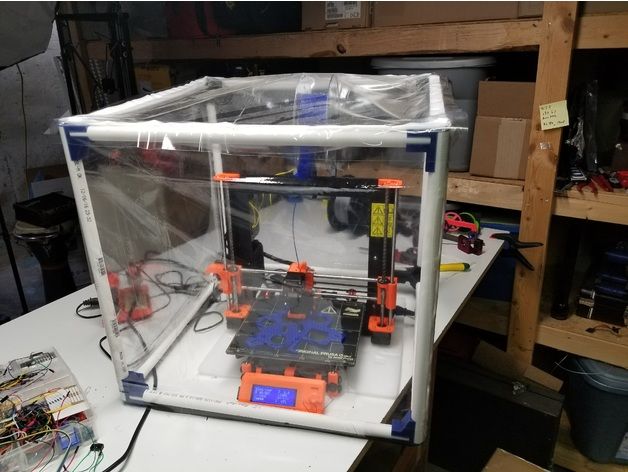 Therefore, if it is possible to avoid this fuss, it is better to avoid it.
An alternative option that I use instead of scotch tape is to apply several layers of ordinary light beer, followed by heating the table to 80-100 ° C until the surface is completely dry and re-applying 7-12 layers. It is necessary to apply the liquid with a cloth moistened with a drink. Among the advantages of this solution: ABS plastic separates from the table on its own when it cools down to about 50 ° C and is removed without effort, the table does not have to be peeled off, and one bottle of beer will last you for several months (if you use the drink only for technical purposes :)).
After we have collected and configured everything, we can start printing. If you have an LCD screen, then the file can be transferred for printing using a regular SD card.
The first results may have bumps and other artifacts - do not worry, this is a normal process of "grinding" the printer elements, which will end after a few print cycles.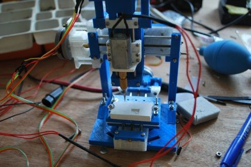
Tips to make life easier (and sometimes save money)
In addition to the small recommendations given in the text above, in this section I will also give a short list of tips that will greatly simplify the operation of a 3D printer and the life of its owner.
- Do not experiment with nozzles. If you plan to immediately print from materials that require high temperatures, then it is better to immediately take the MK10 extruder. On MK8, you can "hang" special nozzles that support high-temperature conditions. But such modifications often cause difficulties and require special experience. It is better to avoid this fuss on the shore by simply installing the right extruder for you.
- Add starter relay for heated table. Improving the power supply system for this important printing part with a starter relay will help solve the known problem of RAMP 1.4 - overheating of the transistors that control the power of the table, which can lead to failure of the board.
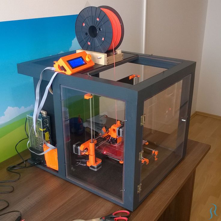 I made this upgrade after having to throw away a few RAMPS 1.4s.
 - Select the correct filament diameter for printing. I recommend using 1.75mm plastic for MK8 and MK10. If we take plastic, for example, 3 mm, then the extruder simply does not have enough strength to push it at an acceptable speed - everything will be printed much longer, and the quality will drop. ABS plastic is ideal for MK8, MK10 will be able to produce products from polycarbonate.
- Use only new and precise X and Y guides. Print quality will be affected. It is difficult to count on good quality with bent or deformed guides along the axes.
- Take care of cooling. During my experiments with various extruders, the MK10 showed the best results - it prints quite accurately and quickly. The MK10 can also print plastics that require a higher print temperature than ABS, such as polycarbonate. Although it is not as prone to overheating as its younger brother MK8, I still recommend taking care of its cooling by adding a cooler to your design.
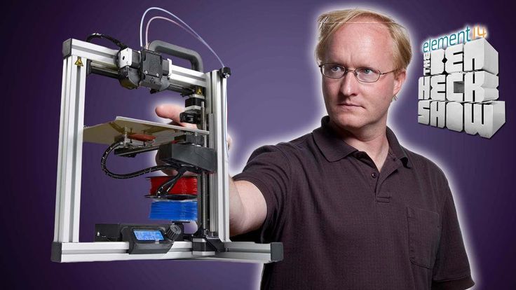 It must be permanently enabled, this option can be configured in Slicer. You can also add coolers to keep the stepper motors at an acceptable temperature, however, make sure that their air flows do not fall on the printed part, as this can lead to its deformation due to too rapid cooling.
 - Consider heat retention. Yes, on the one hand, we are struggling with overheating of the elements. On the other hand, a uniform temperature around the printer will contribute to high-quality printing (the plastic will be more pliable). To achieve a uniform temperature, you can put our printer, for example, in a cardboard box. The main thing is to connect and configure the coolers before that, as described above.
- Consider insulating your desk. Heated table heats up to high temperatures. And if part of this heat leaves properly, heating the printed part, then the second part (from below) just goes down. To concentrate the heat from the table onto the part, you can perform an operation to insulate it.
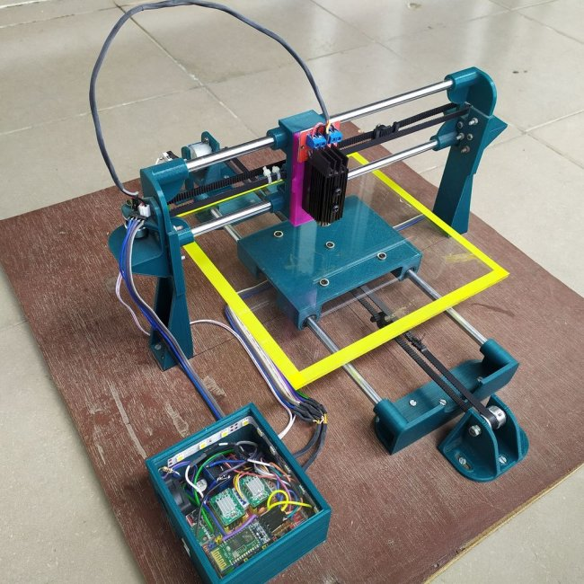 To do this, I simply attach a cork mouse pad to its bottom using stationery clips.
Pins
I am sure that during the assembly process you will encounter a number of difficulties specific to your project. Neither this text nor even the most detailed guides will insure against this.
As I wrote in the introductory part, the above does not claim the status of a detailed assembly manual. It is almost impossible to describe all the stages and their subtleties within the framework of one such text. First of all, this is an overview material that will help you prepare for the assembly process (both mentally and financially), understand whether you personally need to bother with self-assembly - or give up on everything and buy a ready-made solution.
For me, assembling printers has become an exciting hobby that helps me solve some issues in home and work affairs, take my mind off programming and do something interesting with my own hands. For my children - entertainment and the opportunity to get unusual and unique toys.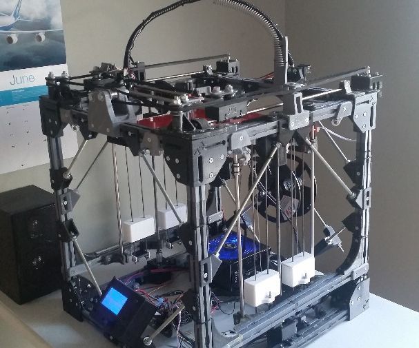 By the way, if you have children whose age allows them to mess around with such things, such an activity can be a good help for entering the world of mechanics and technology.
For everyone, the vectors of using 3D printers will be very different and very individual. But, if you decide to devote your personal time to such a hobby, believe me, you will definitely find something to print :)
I will be glad to answer comments, remarks and questions.
What to read/see
- what can be printed;
- 3D printer forum;
- RepRap community site with model descriptions and assembly instructions;
- printer that prints electronics.
Subscribe to the Telegram channel "DOU #tech" so you don't miss new technical articles.
Topics: DIY, embedded, tech
Homemade 3D printer
Skip to content
Admin Electronics
You can buy a ready-made 3D printer with free shipping in this Chinese store.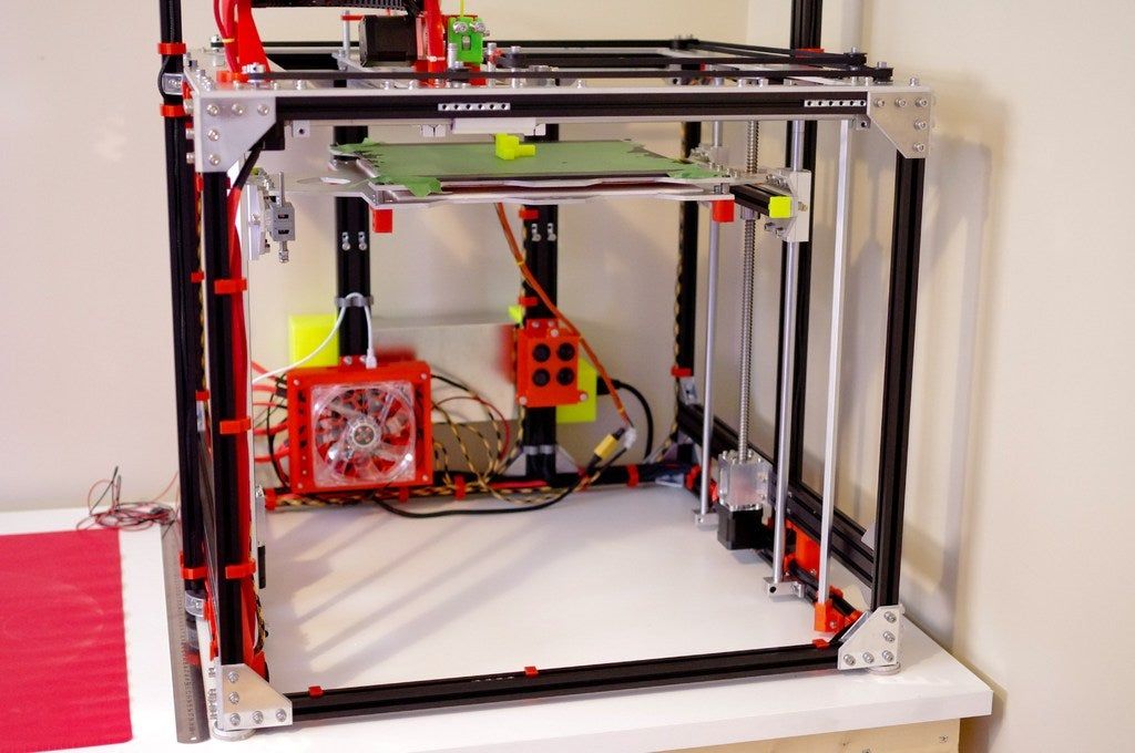 Radio components, arduino at this link.
Contents
- Is it possible to make a 3D printer with your own hands?
- How to build a 3D printer from scratch | 3D printing from scratch
- Plywood 3D printer
- 3D printer construction
- Electronics
- 3D printer table
Is it possible to make a 3D printer with your own hands?
How to build a 3D printer from scratch | 3D printing from scratch
3dprintingfromscratch.com
If you are reading this article, it means that you have probably decided to join the community of 3D printing enthusiasts and learn more about 3D printers, or perhaps you already have some experience in this and are ready to try to create your own. 3D printer. printer from scratch.
Goods for inventors Link to the store.
In this article you will find a general idea of how you can create 3D printers, as well as links to really useful resources where you can find more detailed information with a step-by-step description.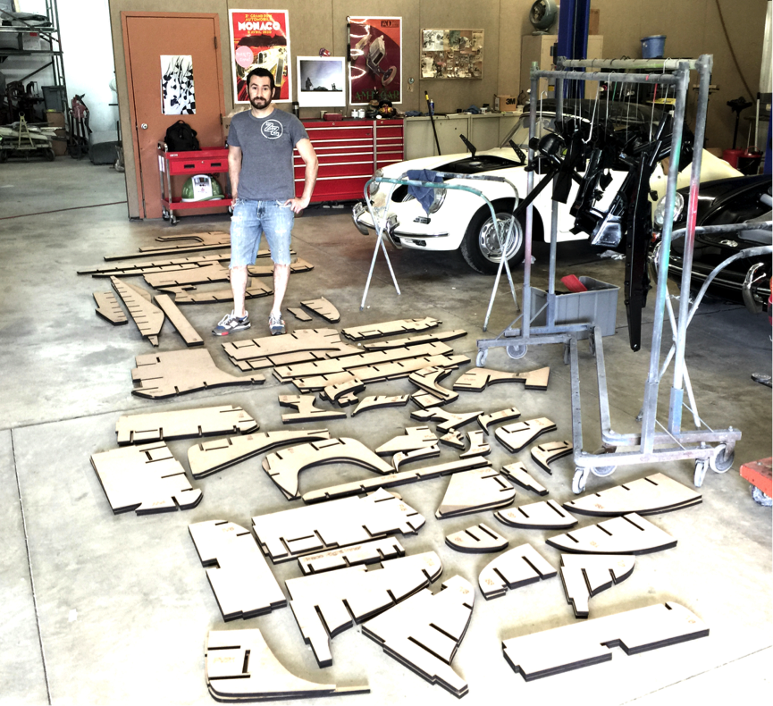
There are now a large number of 3d printers on the Internet, already assembled and ready to print immediately after unpacking them from the box, of course, you also need to buy filament for 3d printer . Keep in mind that not all 3D printers can use the same types of filament, so please read the instructions before purchasing.
DIY electronics in Chinese store.
But for some people who like to do something new with their hands, it might be more interesting to build their own 3d printer from scratch . Based on our research, the 3D printing community is filled with many enthusiasts, so-called do-it-yourselfers, who are passionate about building 3D printers literally from scratch.
You can find many examples of how to build a 3d printer on the RepRap website, but we also want to cover some of the more important steps to give you a general idea of what to expect if you do decide to make your own printer.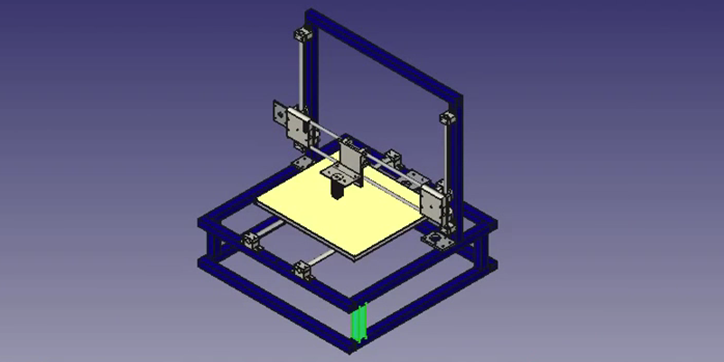
The first step is to find and buy a 3D printer kit. Kits usually contain most of the parts needed to assemble a printer and can be divided into two main types:
Scratch Built 9 3D Printer0051 - This kit is for those who prefer to build things from scratch or in other words go the DIY RepRap route. In addition to some significant advantages, this approach also has its drawbacks. In theory, this could save you some money, and since you're building it from scratch, you'll know all the nuts and bolts in it by the time you can use it and successfully print your first object. The main disadvantage of this method is time. It literally takes a long time to sort through all those hundreds of bolts, wires, belts and more. In the end you still have to choose and buy or build a controller board, but it depends on your skill level.
3D Printer - This type of kit is good if you want to save money and at the same time not deal with all the problems described in the first type of kit.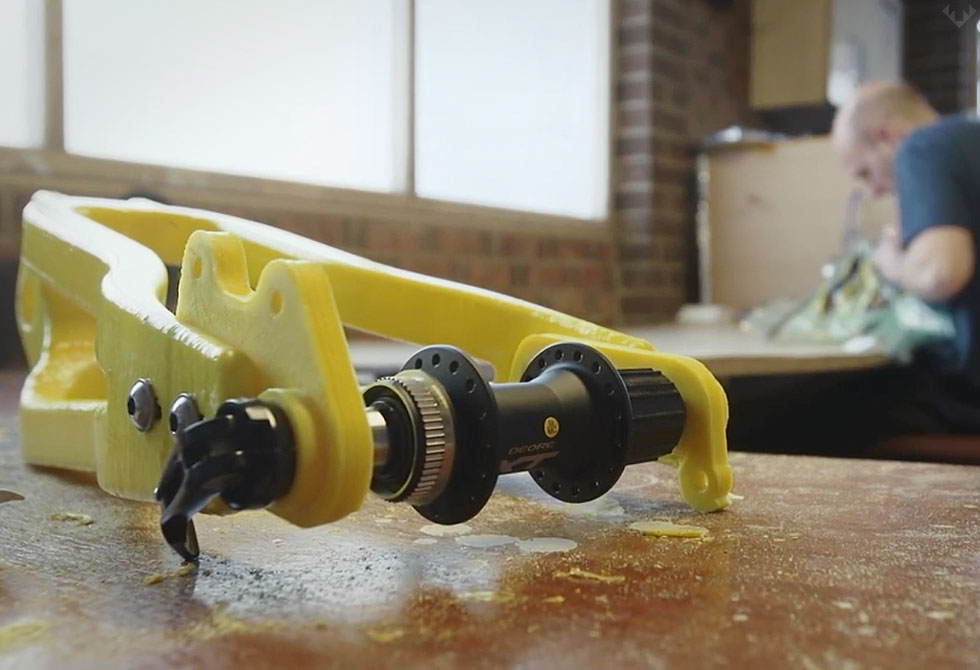 Many manufacturers sell such kits with "easy to assemble" instructions. I doubt it will be as easy as putting together an IKEA chair, so you still have to have a mechanical tilt and be able to understand the basic geometry. Some of these kits do not contain all the parts, and you may need to buy something extra.
The next step is to define the design of your 3D printer. In my humble opinion, most DIY 3D printers don't have very exciting and futuristic designs compared to MakerBot and other brands. But it's also a matter of taste, for some people the design is not very important.
Once you've purchased your 3D printing kit and selected a design, you can start building the most fun and time-consuming part - building your own 3D printer. Get ready for sleepless nights and lots of fun. Perhaps you will come up with something new and present your results to the RepRap community.
When the 3d printer hardware is ready, you also need to add the software component. It mainly performs the following functions: allows you to view and modify 3D graphics objects, as well as convert 3D images into instructions that a 3D printer can understand.
Finally, you can 3d print your first object! If you don't have anything to print, you can find a wide variety of items on dedicated marketplaces like Shapeways, Thingiverse, and more. Before printing, make sure the object you want to 3d print is the correct size and fits on the printer frame.
Plywood 3D printer
First, see how this printer works
Now in detail how the device was assembled
Recently, the author of the Yar channel promised to show in detail the design of his 3d printer and tell where you can get components for it. Today it will not be possible to make a video on how to build a 3d printer from start to finish, because the printer is already ready. But maybe in the near future a video will appear on the channel on how to make a 3d printer from wood from scratch.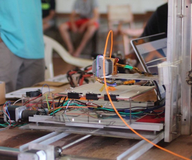 Because it will be redone.
Construction of the 3D printer
Basically, the printer is made of wood, for its construction a single board was used, which the author had. He doesn't have a circular, so the board isn't loosened narrower, it's so big and heavy. In order to assemble the frame, I sawed the board into several parts, glued it here, twisted it with self-tapping screws here, and this made up the frame design of this printer. The board is thick, so stiffness with a margin.
Parts from old scanners are used for axes. More precisely, for two axes of three 3d printers. That is, there are two guides for the Z axis. And for the X axis, two guides.
The Y axis hangs on an aluminum profile, quite thick too. And homemade carriages from ordinary ball bearings. This is what was in the garage just.
In fact, this part should have been used on the Z axis, this will be taken into account when reworking.
Homemade 3D printer
The carriages are also driven by motors from scanners, with native gearboxes, with native belts.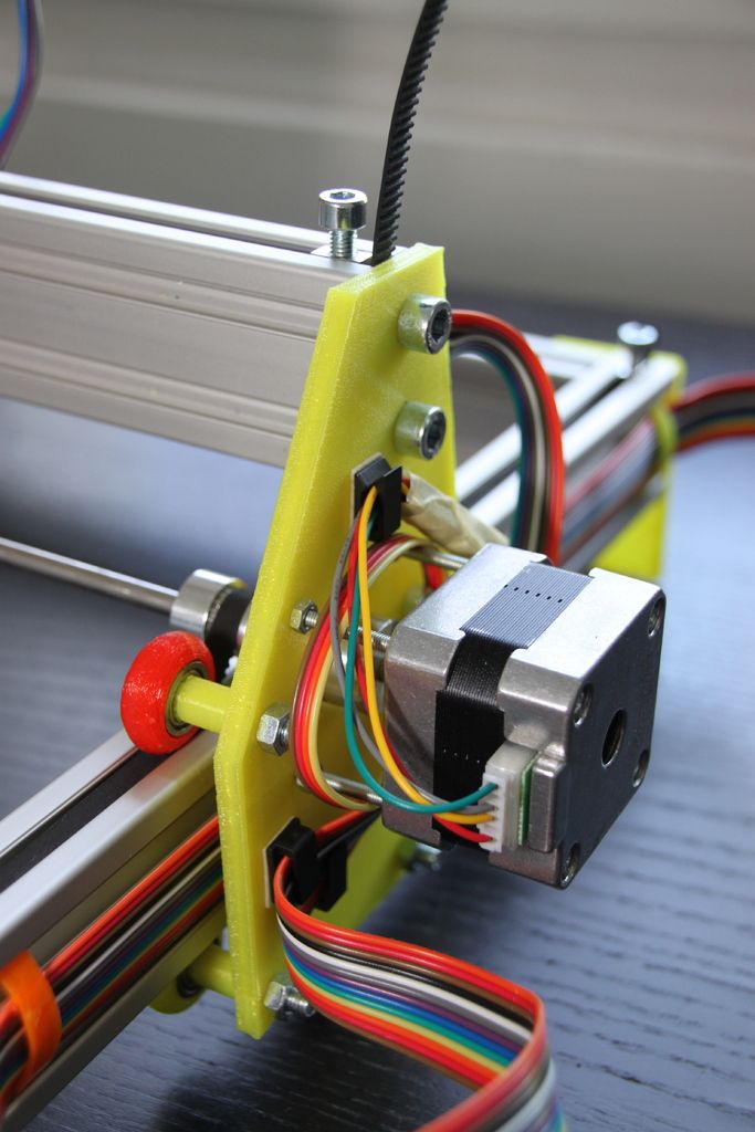 Here, however, I had to use a gearbox from one scanner, and a motor from another, so that the movement of this axis coincided in steps with the Y axis.
There is also a motor from the scanner on the Z axis. It was unipolar, that is, five wires sticking out of it, now four wires are sticking out of it. To do this, I had to cut the jumper there. With a converted gearbox that has the ability to turn just such an M5 stud. And there are two of these pins: one on the right side, the other on the left. They are tied together with a belt.
For some reason, other printers have two motors. But the master decided that there was no difficulty in using the belt. It’s not even clear why they make two motors.
In order to align the axis, I used paper pads. That is, a lot of small paper sheets that I put under the fulcrum of the guides in order to bring them in parallel with each other. They are, as already shown, right here, right here, right here.
These pads are also used for rough adjustment of the table.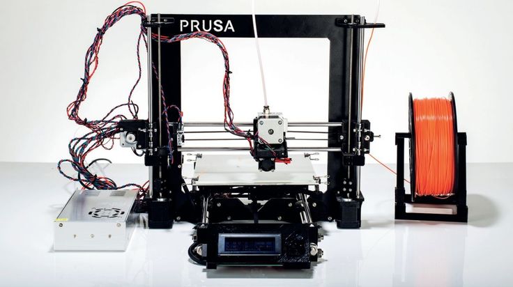
Electronics
Homemade electronics. It is definitely better to buy it, because in the end I got a lot of crap. But that's not the point. The bottom line is that the electronics are made by Arduino Uno Chinese. Here, with a margin, are field-effect transistors. Here are two even with a radiator. Because before it was already at 200 watts. And, of course, four drivers are worth it. Arduino can be bought at this link.
There is currently no extruder on the 3D printer, or rather, its cold end. There is only the nozzle itself with a heating block. All this is because he started reworking it for a lighter motor. Initially, this motor was here, everything worked perfectly. To be able to fly them faster, you need to reduce weight. Plus, I freed this motor for one of the axles, and bought another one for it. All this is done in order to make the printer a little faster in the future.
Speaking of speeds. Scanner motors for 12 V allow you to reliably have a speed of about 25 millimeters per second. At higher speeds, they may begin to lose steps.
Table for 3D printer
In the previous video you could see another table, it is quite large and made only of glass. But this is a big problem, because the glass cracks from strong uneven heating. So I had to give up this table.
Made from scanner glass with steel tie wire underneath. And on the other hand, it is to some extent insulated with glass tape.
The second table is much smaller, because there was just such a large piece of metal. Already made under replaceable glass. It can be attached here with clothespins. By the way, it also cracked, it was originally in size.
Standard 5 watt resistances are screwed to this sheet of steel.
It is held on the carriage with the help of these trimming bolts 3 pcs., with nuts screwed on them. They sit on the thread lock, spinning quite tight. Due to this, they can be adjusted in relation to the axes of the printer.
This is one of the few parts printed on this printer.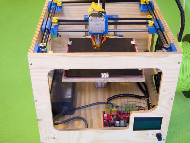 This is the Z axis bearing support. Why did the craftsman print it, because the one that was made of wood was quite skewed. Due to which, on the parts that were printed on this printer, a noticeable unevenness of the layers appeared. That is, with layers 0.1 mm or 0.2 mm thick, they looked like they were about 0.7 thick. And the bonding strength between the layers was low.
One of the serious shortcomings of this 3D printer is the lack of ends. That is, the axes do not know where the beginning is, and you have to set them manually.
If this does not cause any problems with the X, Y axis, and the author of the model probably did not even make endings on them. For the reason that you can manually set the center of the printer to any place, and thus print several parts in succession from one G-code. But setting the Z-axis manually is very inconvenient. This takes about 5 minutes each time before each print.
Another disadvantage that is common to many printers is that it is open.