Gcode for 3d printing
3D Printing Gcode Cheat Sheet: Basic Demands
Jun 14, 2020
Just as humans use language to interpret and understand actions and commands, 3D printers have their own language: Gcode demands.
Gcodes instruct 3D printers on every action the printer must take, including movements, speed, temperatures, and much more. Having a basic understanding of what gcodes are will help you in your 3D printing processes by allowing you to work more efficiently and possibly even more creatively.
We’ll review all the basics you need to know about gcodes: how they work, how to read a line of gcodes, and a gcode cheat sheet.
Basic Guide to 3D Printer GCodesSimply put, a gcode is a programming language that tells the printer what to do. These actions can include where the printer head goes, extruder temperature, bed temperature, pauses, printer head speed, and more.
Gcodes are actually used for a variety of machines, not just 3D printers! Cutting tools likes lathes and mills also rely on Gcodes.
On your computer, a g-ode will be a .gcode file. You can view the line by line code of the gcode by opening it in a text editor.
Gcodes are typically hundreds of pages long since they are directing every single action the printer is taking. Although gcodes are considered a fairly easy coding language, it is not recommended to write your own gcode: they are very complex, long, and if done incorrectly they can damage your printer. This leads us to our first question:
How are GCodes created?Gcodes are created when you import an STL file into a slicing software. The slicing software will then configure a code based on the specificities of your 3D print’s design. The code is then sent to your 3D printer to bring the digital file to life.
Gcodes come in towards the end of the 3D printing workflow, but they are crucial for the success of your 3D print coming to life. A 3D design is made in a CAD software and exported as an STL, the STL file is then imported into a slicer software, like BCN3D Cura. Within the slicer software, you set your parameters, and then the software will create and export the .gcode. That file is then sent to the 3D printer through an SD card or wifi. The printer then uses each line of code for every action that it will take.
Gcode is a fairly simple and easy to understand code language. Each line of code tells the printer to perform one specific action, which is why there can be thousands of lines for just one print!
Although called gcode, it is actually made up of several different letters and numbers that have specific meanings or instructions. Also, gcodes don’t always start with the letter G. Geometric commands, or commands that deal directly with printing the object, start with a G. Non-geometric commands start with an M. An example of a non-geometric command could be setting the bed temperature or extruder temperature.
Here is an example of what a Gcode could look like:
56 G1 F2200 X22. 3 Y56.4 E5.9
Let’s dive into the specific meaning of each letter and number you see:
- The first number: The first number you will see on a line of gcode is just specifying which number line you are on. Gcodes all exist on their own line, with the first line being 1.
- G or M followed by a number: A G or M with its corresponding number indicates a specific action that the printer must take. For most printers, these letter-number combinations are universal. Think of this as the “what” of the printer’s action, and the following numbers and letters as the “how.”
- X followed by a number, and Y followed by a number: These letter-number combinations indicate the x and y coordinates of where the printer head must go. Some gcodes may also include a Z coordinate.
- F followed by a number: The F in the gcode indicates the feed rate. Essentially, this tells the printer how fast or slow to move the printhead.
- E followed by a number: This tells the printer how much filament will be discharged from the extruder.

There are some additional letters and numbers that are used for M codes. For example, T indicates which extruder is being used, starting with T0 and moving up based on the number of extruders. S indicates the degree in celsius for an extruder.
Gcode Cheat SheetNow that you know what the letters stand for, let’s take a look at some common Gcode commands and their meanings.
G0 and G1: MoveThis commands the print head to move in a straight direction. The print head will move to the indicated X and Y coordinates. The difference between G0 and G1 is filament extrusion, as G1 commands the printer to push out filament while G0 moves the print head without filament extrusion.
The E and F in the code will tell the printer how quickly it needs to move to that location and how much filament should be extruded during this time. This is the most commonly used gcode command.
G90 and G91: Absolute and Relative PositionAbsolute position (G90) means that the printer head must move to the exact position indicated by the x and y coordinates.
Relative position (G91) means that the print head must move using the numerical values of the x and y coordinates, but not necessarily to those spots.
For example, if a line of code reads G90 G1 X40, then the print head must move to the X=40 position on the bed. But, if the line reads G91 G1 X40, then the print head must move 40mm from where the print head is currently located.
G28: HomeThis command sends the print home back to its “home”, the X0 andY0 coordinates.
M104 and M109: Heat ExtruderBoth M104 and M109 will heat the extruder to a specific temperature, the only difference is that an M104 command will allow the printer to take other actions while the extruder is heating and an M109 command will pause all activity until the final temperature is reached.
M140 and M190: Heat Print BedM140 and M190 work similarly to the above M commands except they deal with the temperature of the printing bed. An M140 command means the printer can take other actions while the bed is heating, and an M190 command will pause all actions until the bed is fully heated.
Some professionals may go their entire career without ever dealing with Gcodes, but having a basic understanding of how they work can actually aid you in your 3D printing workflow. Understanding how your 3D printer interprets commands and takes actions can help you if any problems occur with your printer and can even help you come up with new creative ideas for print projects.
Beginners Guide to 3D Printing G-Code Commands
Did you know that 3D printers have their own language? Today, many desktop 3D printers use a numerically controlled programming language made up of a series of commands called G-Code. Most of these commands start with a G (hence the name), but there are also some common machine-specific codes that start with an M. These commands tell your 3D printer exactly what actions to perform – where to move, what speed to use, what temperatures to set, and much more. For any maker, it is beneficial to have a basic knowledge of G-Code to understand how your 3D printer works, debug or perform maintenance on your machine, and verify your print files. This guide will explain the 10 most commonly used commands, what they do, and how to edit them in Simplify3D.
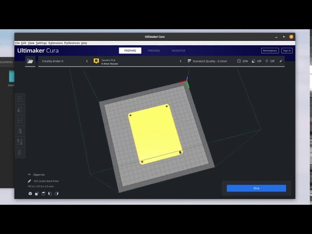
When slicing your model in Simplify3D the software will automatically generate the G-Code commands necessary to complete the print. You can view these commands by clicking “Save Toolpaths to Disk”, selecting a location for the file on your hard drive, and then opening the .gcode file in a text editor like Notepad or TextEdit. If you happen to be using Notepad++, you can download this handy XML file that will enable syntax highlighting for your gcode files, just like the image at the top of this article. To import the file in Notepad++, go to Language > Define your language, click Import, and select the XML file.
Although G-Code is the standard language for most 3D printers, some machines may use different file formats or commands. Even if your printer uses a different file format such as an .x3g file, please note that Simplify3D will still export both the .gcode and .x3g files to the location that you select. This is quite useful, as many of the other file formats are actually binary files. Viewing the text in the gcode file is much easier than readings lots of 1’s and 0’s in the binary files!
After you open your .gcode file in a text editor, you will notice that each command is typically listed on a separate line. The start of the line tells you what type of command it is, and then there may be several additional arguments that follow. You can even add comments within the file by placing a semi-colon before the comment so that it is ignored by the machine. So now that you have seen an example of what your 3D print files look like, here is our list of the 10 most common commands you need to know.
The 10 Most Common G-Code Commands for 3D Printing
For each command, we will provide a description of what the command does, specify what arguments may be needed, and even provide a few sample commands so that you can see how it is commonly used.
G28 – Perform Homing Routine
This command tells the printer to run its homing sequence, which will move the toolhead to the far edges of the machine until it contacts the endstops at these locations. Most of your print files will begin with this command so that the printer starts from a known location. This is also a useful way to quickly move one axis out of the way, which may be useful at the end of a print so that you can remove your part.
Arguments:
If no arguments are provided, the machine will home all 3 axes. You can also specify which exact axes you want to home by adding an X, Y, or Z to the command.
Example usage:G28 ; home all axes (X, Y, and Z)
G28 X Y ; home X and Y axes
G28 Z ; home Z axis only
G90 and G91 – Set Positioning Mode
Your printer can use either absolute or relative positioning. Absolute positioning means that you will be telling your 3D printer to move an exact XYZ coordinate. Relative positioning is used when you want to tell the printer how far it should move from the current location. Send a G90 command to tell your printer to use absolute positioning, or a G91 for relative positioning. The majority of your gcode file will likely use absolute positioning, since the slicer has already determined the exact XYZ coordinates to move to. However, if you don’t know the previous position of the toolhead, or you simply know that you want to move the head a certain distance along an axis, you can use relative positioning. While G90 and G91 control the positioning mode for the X, Y, and Z axes, you can also use M82 or M83 to set your extruder (E-axis) to absolute or relative positioning.
Arguments:
None
Example usage:G90 ; use absolute positioning for the XYZ axes
G1 X10 F3600 ; move to the X=10mm position on the bed
G1 X20 F3600 ; move to X=20mm
G91 ; use relative positioning for the XYZ axes
G1 X10 F3600 ; move 10mm to the right of the current location
G1 X10 F3600 ; move another 10mm to the right
G1 – Linear Movement
This command probably makes up 95% of your gcode files, so it is a good one to learn! The G1 command tells your printer to move in a straight line to the location that you specify. You can use this to move just a single axis, or multiple axes at once. Keep in mind that your extruder is controlled just like any other axis, so you can also use this command to extrude or retract filament from the nozzle.
Arguments:
Use X, Y, or Z values to tell the printer what position to move to. Keep in mind that these values will obey the current positioning mode, so you can specify them using either absolute or relative coordinates. Include an E value if you want to move the extruder as well. The E value corresponds to the position of your filament spool, so if you move the E axis by 10mm, that would cause 10mm of your filament to be pushed into the nozzle. Since the nozzle diameter is usually much smaller than your filament diameter, 10mm of filament pushed into the nozzle may create an extrusion that is hundreds of millimeters long! For this reason, the E values that you will see in your file are typically quite small compared to the X, Y, and Z values. Finally, you can use an F value to tell the printer what speed to use for the movement. This speed must always specified in units of mm/min, so even if you use mm/s in your slicing software, you will still need use mm/min anytime you are sending a command directly to the printer.
Most printers support “sticky” coordinates, which means that you only need to specify the arguments for the axes you actually want to move. So if you only wanted to move the Z axis, you would just include the Z argument as well as an F value to define the speed.
Example usage:G1 X0 Y0 F2400 ; move to the X=0 Y=0 position on the bed at a speed of 2400 mm/min
G1 Z10 F1200 ; move the Z-axis to Z=10mm at a slower speed of 1200 mm/min
G1 X30 E10 F1800 ; push 10mm of filament into the nozzle while moving to the X=30 position at the same time
G92 – Set Current Position
Use this command to set the current position of your axes. This can be useful if you want to change or offset the location of one of your axes. One of the most common uses for this command is actually with your E axis (the filament position). You can quickly override the current filament position so that all future commands will now be relative to this new value. It is common to do this at the start of each layer or right before a prime or retraction command.
Arguments:
Specify the absolute coordinate for any axis that you wish to overwrite. You can include the X, Y, Z, and E axes. If you do not include one of these axes in the command, the position will remain unchanged.
Example usage:G92 E0 ; set the current filament position to E=0
G1 E10 F800 ; extrude 10mm of filament
M104 and M109 – Extruder Heating Commands
Use these commands to set the temperature of your extruder. The M104 command starts heating the extruder, but then allows you to run other commands immediately afterwards. The M109 command will actually wait until the desired temperature is reached before allowing any other commands to run. For this reason, you will frequently see an M109 at the top of your Simplify3D gcode files, as this allows the extruder to reach the necessary temperature before the print begins.
While most machines use M104 and M109, some firmwares may use slightly different commands. For example, if you are using a machine that reads x3g files, then you may use an M133 command for stabilizing your extruder instead of M109. If you are using a machine that runs a variant of the FlashForge Dreamer or Dremel firmwares, you’ll want to use an M6 command to stabilize your extruder. You can check what firmware type you are using in Simplify3D by going to Tools > Firmware Configuration.
Arguments:
The S value specifies the extruder temperature in degrees Celsius. The T value can be used if you have more than one extruder, as it allows you to specify which exact extruder temperature you want to set. If you have a dual extrusion machine, typically T0 is the right extruder, and T1 is the left extruder. If you only have a single extruder machine, you can typically omit the T parameter entirely.
Example usage:M104 S190 T0 ; start heating T0 to 190 degrees Celsius
G28 X0 ; home the X axis while the extruder is still heating
M109 S190 T0 ; wait for T0 to reach 190 degrees before continuing with any other commands
M140 and M190 – Bed Heating Commands
Use these commands to set the temperature of your heated build platform. The syntax is very similar to the M104 and M109 commands mentioned above. Sending the M140 command begins heating the bed, but allows you to run other commands immediately afterwards. The M190 command will wait until the bed temperature is reached before allowing any other commands to run. Keep in mind that the heated bed on your printer may take several minutes to reach elevated temperatures. So don’t be surprised if you see your printer pausing while waiting on an M190 command to finish heating the bed. Because this process can take a long time, it may be a good idea to start heating the bed at the beginning of your routine using an M140 command, which would allow you to do other actions such as homing or nozzle purging while the bed is still pre-heating. Just make sure to include an M190 before the print begins, as the bed temperature can be an important factor for first layer adhesion.
As with the M104 and M109 commands, these bed heating commands can differ depending on what firmware you are using. If your machine reads x3g files, then you can use the M134 command for stabilizing your bed instead of M190. If you are using a variant of the FlashForge Dreamer or Dremel firmwares, you’ll want to use an M7 command to stabilize your bed.
Arguments:
The S value specifies the bed temperature in degrees Celsius. No other arguments are typically needed, as most machines only have a single heated build platform.
Example usage:M140 S50 ; start heating the bed to 50 degrees Celsius
G28 ; home all 3 axes while the bed is still heating
M190 S50 ; wait until the bed reaches 50 degrees before continuing
M106 – Set Fan Speed
This command allows you to set the speed of your printer’s part cooling fan. This is an external cooling fan that is pointed towards the part that you are printing. Keep in mind that your printer may also have an extruder fan that helps cool the extruder drive mechanism, so make sure you are looking at the correct fan first. While most printers have an external cooling fan, there are a few exceptions, so check your machine first to make sure it has an external cooling fan that you can control.
Arguments:
The S value sets the speed of the cooling fan in a range between 0 (off) and 255 (full power).
Example usage:M106 S255 ; set the fan to full speed
M106 S127 ; set the fan to roughly 50% power
M106 S0 ; turn off the fan completely
How to Send or Edit G-Code Commands
If your machine accepts normal gcode files like most RepRap machines, then a great way to test different commands is by manually sending them one-at-a-time to see how your printer responds. You can do this within Simplify3D by going to Tools > Machine Control Panel. Once in the Machine Control Panel make sure you are connected to your 3D printer and then use the Communications tab to send your printer a line of G-Code. Just type the command that you want to send at the bottom of the window and then press the Send button. None of the commands mentioned in this article are permanent, so you can always reboot the printer if you want to stop what the machine is doing or get back to a fresh state.
Once you feel comfortable with the commands, you may find that you want to run the same series of commands before or after each print. Thankfully, Simplify3D gives you the ability to customize the routines that are run at the start and end of each print, so you can easily update your settings so that your 3D printer automatically performs these actions. To do this, click “Edit Process Settings” and then select the Scripts tab. There are several different scripts on this tab that you can edit. Each one is used at different times during your print. For example, the Starting script is used at the very beginning of the print, while the Ending script is run at the very end of the print. Depending on where you want to make your changes select the appropriate categories and start editing. The default profile that Simplify3D provides for your 3D printer will already include scripts that we have tested and verified, so you can use these as a starting point.
Each time you make a change to these scripts, you can try running a quick test print to make sure the printer behaves like you would expect. Once you are happy with the changes, you can use Simplify3D’s profile management system to permanently save these new settings for future prints. You can even create multiple versions of your profile if you want to keep track of your changes along the way.
We have now covered all the fundamentals you’ll need to begin testing G-Code on your 3D printer. If you are interested in other tutorials like this that can help teach you the basics of 3D printing, click here to view our full article library.
View the Complete Article Library
G-CODE in Russian for 3D printing (Mini-guide)
Often, for high-quality printing, and especially when selecting print parameters, it is necessary to be able to read and edit the G-code during calibration.
A commonplace example: setting your own values for the "Temperature Tower" or creating start and end blocks of codes in slicers for a specific printer.
On some sites (like reprap.org/wiki/G-code) on the Russian-language pages, the commands are only partially described in Russian, and the rest in English. On some domestic sites, the commands are translated into Russian, but some are given with errors - stupidly copy-paste a clumsy translation.
Tired of searching through different sites, trying to find the CORRECT description of a particular command and its parameters.
I made myself such a mini-reference book. I'll be glad if anyone else finds it useful.
I tried to describe the maximum number of commands used, except for very specific ones.
(Yes, special commands for deltas, for example, sorry, I consider them specific and not necessary for me)
However, most commands are supported by all printers and firmware.
Attention! Compliance of commands and parameters is checked only for Marlin firmware.
G-commands
G0(G1) Xnnn Ynnn Znnn Ennn Fnnn – movement.
G0 - fast idle
G1 - linear working travel
Xnnn, Ynnn, Znnn – coordinates.
Еnnn - amount of extruded material in mm (with negative values - retract).
Fnnn – travel speed in mm/min (this speed will be used until the next change).
G0 X12 (will move 12mm in X)
G0 F1500 (Set travel speed to 1500 mm/min.)
G1 X90.6 Y13.8 E22.4 (Move 90.6mm in X and 13.8mm in Y while extruding 22.4mm of material.)
G4 .
Pnnn - Timeout, in milliseconds
Snnn - Timeout in seconds.
"G4 S2" and "G4 P2000" - equivalent to
G10 - Plastic rollback (Retract)
Filament rollback according to M207 settings.
G11 - Plastic feed
Feed / reposition the head according to M208 settings.
G20 - Inch unit setting
G21 - Setting the units in millimeters
From now on, the reading will be in inches/millimeters.
G28 - Move to start ("home") until limit switches actuate
G28 – home on all axes.
G28 X Z - Move home only in X and Z axes
G29 - Create table curvature mesh (MESH_BED_LEVELING)
The command allows you to create a compensation (Z-height) grid and use it later when printing. The grid can be used repeatedly even after the printer is turned off.
After using the G28 command, the mesh created by the G29 command flies off.
It is necessary to save the rhinestone mesh after it has been created! To recall the grid from memory, use the M420 command.
Be sure to use G28 before using G29, otherwise the mesh will be incorrect.
Creating Mesh Bed Leveling manually (via commands):
1. Enter G29 S0 to start meshing.
2. Enter G29 S1 to set the first grid point.
3. Align the nozzle with paper (as usual).
4. Enter G29 S2 to save the value and jump to a new point
5. Repeat steps 3 and 4 until the creation procedure is completed.
6. Enter M500 to write the resulting mesh to EEPROM.
Creating Mesh Bed Leveling using the printer menu (the function must be active in the firmware):
1. Select Prepare followed by Auto home (aka G28 command).
2. Select Prepare and then Level Bed.
3. Wait for on-screen instructions to begin. Press the "twist" on the screen when the inscription "Click to Begin" appears. The head will go to the first grid point.
4. Use the thumbwheel to raise or lower the nozzle to align the nozzle with the paper. Same as when leveling the table. After you have achieved the desired gap between the nozzle and the piece of paper, press the "twist". The head will move to a new grid point.
5. Repeat step 4 until the program has passed all points.
6. When finished, enter the Control menu and select the Store memory item to save the created mesh to EEPROM.
To use the grid stored in EEPROM when printing, use the command
M420 S1 (See M420).
G90 - Setting absolute coordinates
All coordinates are absolute relative to the machine origin.
G91 - Set relative coordinates
All coordinates from now on become relative to the last position. Marlin translates all axes into relative coordinates, including the extruder.
G92 Xnnn Ynnn Znnn Ennn - Set position
This command can be used without any additional parameters.
G92 - reset all axis coordinates to zero.
Xnnn - new X coordinate
Ynnn - new Y coordinate
Znnn - new Z coordinate
Ennn - new extruder position
Example: G92 X10 E90
M-commands
M17 - Enable/Enable all stepper motors
M18 - Remove current from motors
Motors can be turned by hand. Command analog M84
M20 - List of files on SD card
M21 - SD card initialization
If the SD card is loaded when the printer is turned on, this will happen by default. The SD card must be initialized for other SD card functions to work.
M22 - Release SD card
The specified SD card will be released. On future (random) read attempts, a guaranteed error occurs. Useful before removing the SD card.
M23 - Select file on SD card
Example: M23 filename.gco
M24 - Start/continue printing from SD card
The printer will print from the file selected with the M23 command.
M25 - SD card print pause
M28 - Start writing to SD card
Example: M28 filename.gco.
A file is created on the SD card, designated as filename.gco (if the file exists, it is overwritten) and all subsequent commands to the printer are written to this file.
M29 - Stop writing to SD card
Example: M29 filename.gco
The file opened by the M28 command is closed and all subsequent commands are executed by the printer in normal mode.
M30 - Delete file from SD card
Example: M30 filename.gco. filename.gco will be removed.
M32 - Select file and start printing from SD card
Example: M32 filename.gco.
Used for SD card printing and works the same as M23 and M24
M80 - Enable ATX Power Supply
Puts the ATX power supply into sleep mode. Does not work on electronics without sleep mode.
M81 - Turn off the ATX power supply
M82 - Set the extruder to absolute mode
M83 - Set extruder to relative mode
Allows extruder to be extruder in absolute/relative units
M84 SNNN X, Y, Z, E - transfer motors to the waiting mode of
SNNN - time per seconds.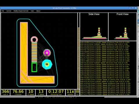
If a timeout is specified with Snnn, this command simply sets the stepper motor inactivity timeout.
If no motors (X,Y,Z or E) are specified, this command immediately disables all.
If one or more axes are specified, this command disables the specified ones immediately. For example, "M84 S10" will put stepper motors into standby mode after 10 seconds of inactivity.
M92 Xnnn Ynnn Znnn Ennn - Set the number of steps per axis per unit
Ennn - steps per unit for extruder
Examples: M92 X87.489 Y87.489 Z87.489 or M92 E420
Allows you to set the number of steps per unit (usually mm) for motors. These values are replaced with the values from the firmware at power up unless written to the EEPROM see M500.
M104 Snnn - Set extruder temperature and DO NOT wait
Snnn - Set temperature
Example: M104 S190
Sets the temperature of the active extruder 190C and immediately returns control (that is, DOES NOT WAIT for the extruder to reach the set temperature). See also M109
M105 - Get Extruder Temperature
Gets the temperature of the active extruder and hot bed in degrees Celsius. The temperature is transmitted to the connected computer. The response sent to the computer might look like this: ok T:201 B:117
M106 Snnn - Turn on the fan blowing part
SNNN - fan rotation of fan from 0 to 255 (127 - 50% speed)
m107 - turn off the fan
m108 - cancel the heating 9000 9000 temperature set by M109 and M190, continues printing.
M109 Snnn - Set extruder temperature and wait
Sets the temperature in Celsius and waits for it to be reached. See also M104
M110 Nnnn - Set current line number
Nnnn - Line number
Example: M110 N123
In this example, the number of the current line 123 is set. Thus, it is expected that the next line after this command will be 124.
M112 - Emergency Stop
m114 - receipt of current positions 9
M115 - Get a firmware version
m119 - get the status of ends
m140 - set the temperature of the table and DO NOT wait
Example: M140 S65
Sets the table temperature to 65C and immediately returns control (ie DOES NOT WAIT for the table to reach the set temperature). See also M190
M190 - Set table temperature and wait
Sets the temperature in Celsius and WAITS to reach it. see M140
M200 Dnnn Tnnn - Set the REAL diameter of the filament rod.
Dnnn – diameter in mm.
Tnnn – extruder number. (can be omitted for single extruder printers)
Example: M200 D1.65
Used to calculate the actual extruded volume.
See M404 for rating setting.
M201 Xnnn Ynnn Znnn Ennn - Setting of the maximum accelerations (in mm/s in sq.)
for axes.
Ennn - accelerations in mm/s in sq. for the extruder.
Only one/two of the parameters can be used.
Example: M201 X1000 Y1000 Z100 E2000
Use M500 to store parameters in EEPROM
M202 - Setting the maximum acceleration for simple (idle) movement.
!Not used in Marlin! V mm/s in sq. Example: M202 X1000 Y1000
M203 Xnnn Ynnn Znnn Ennn - Setting the maximum speed (in mm/s)
Xnnn, Ynnn, Znnn - max speed for axes
Ennn - max extruder speed.
Only one/two of the parameters can be used.
Example: M203 X6000 Y6000 Z300 E10000
Use M500 to store parameters in EEPROM.
M204 Pnnn Rnnn Tnnn - Acceleration setting (in mm/sec. in sq.)
Pnnn - Printing acceleration
Rnnn – Retract Acceleration
Tnnn - Accelerations during idle movements
Only one/two of the parameters can be used.
Example: M204 P800 T3000 R9000
Use M500 to store parameters in EEPROM.
M205 Xnnn, Znnn, Ennn - Setting the maximum jerk (jerk) (mm / s)
Xnnn - jerk along the X and Y axes. (Jerks are the same along these axes)
Znnn - jerk along the Z axis.
Ennn - extruder jerk.
Only one/two of the parameters can be used.
Example: M205 X30 Z5 - Set jerk X/Y = 30, Z jerk = 5.
Use M500 to store parameters in EEPROM.
М206 Xnnn, Ynnn, Znnn - Set offsets relative to limit switches (zero)
Similar to G92 command, but these offsets can be written to EEPROM see M500.
Example: M206 X10.0 Y10.0 Z-0.4
M207 Snnn Fnnn Znnn - Set retract parameters (bar retraction)
Snnn - positive retract value in mm.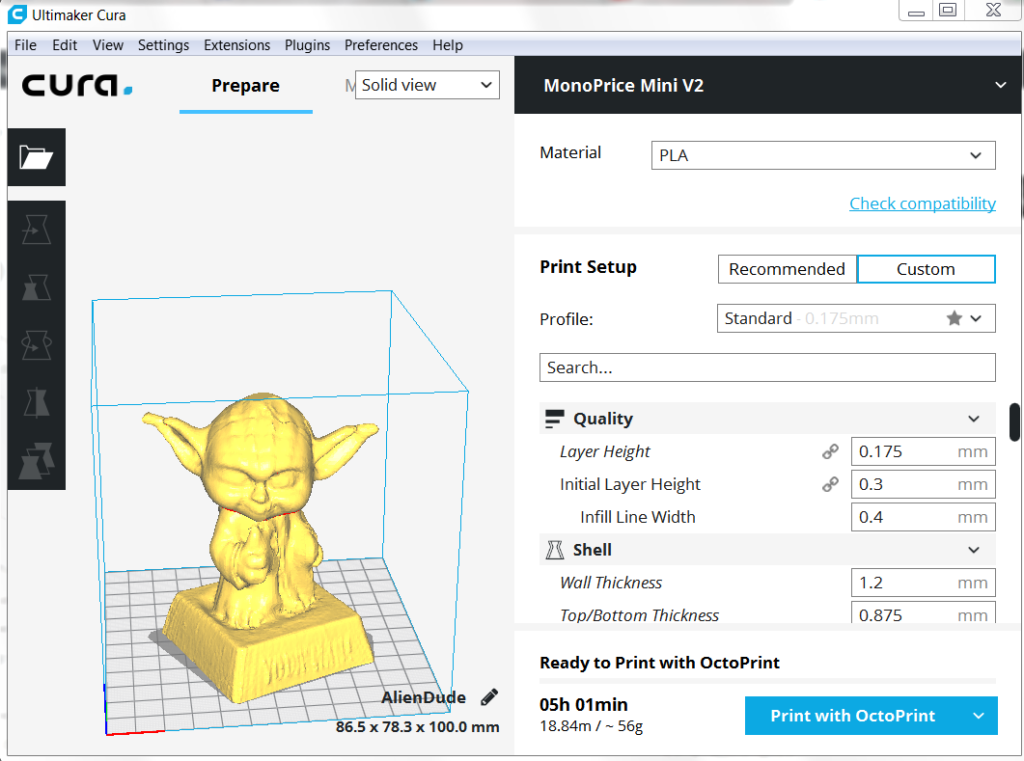
Fnnn – feedrate mm/sec.
Znnn - lift (lift) of the head along the Z axis in mm during retract. (Helps avoid hitting the model)
Example: M207 S4.0 F2400 Z0.075
Used subsequently for G10 and G11 commands.
Use M500 to store parameters in EEPROM.
M208 Snnn Fnnn – Bar feed recovery parameters after retract
Snnn – positive feed value in mm.
Fnnn – feedrate mm/sec.
Use M500 to store parameters in EEPROM.
M209 Snnn – On/off automatic retraction
Snnn – value 1 – on, 0 – off
Used if the slicer does not support the G10 and G11 commands.
Each extrusion command will be classified as a retract, depending on the value (positive or negative).
M218 Tnnn Xnnn Ynnn – head offset setting
Tnnn - head number
Xnnn, Ynnn – X,Y coordinates.
Example: M218 T0 X50 Y10. 5
5
M301 Hnnn Pnnn Innn Dnnn — Write hotend PID parameters(!)
Hnnn – extruder number. h2 - the first exruder (hotend).
Pnnn - Proportional gain (Kp)
Innn - Integral factor (Ki)
Dnnn - Derivative coefficient (Kd)
Example: M301 h2 P1 I2 D3
Use M500 to store parameters in EEPROM.
See M304 for writing table PID.
M302 Snnn - Allow extrusion at Snnn and above.
Snnn - Set temperature
Example: M302 S170 – enable extrusion (turn on the extruder motor) at a nozzle temperature of 170C and above. M302 S0 - extrude at any temperature.
M303 Ennn Snnn Cnnn - Start PID calibration process for table/hotend
Ennn - E0 hotend, E1 table.
Snnn is the calibration temperature.
Cnnn – number of calibration cycles. More cycles - more precise parameters.
Example M303 E1 C8 S110 – table PID calibration at 110C for 8 cycles.
The PID parameters will be displayed as a string on the terminal screen of a program running in connection with the printer, such as Repetier-Host.
M304 Pnnn Innn Dnnn - Write table PID parameters(!)
Pnnn - Coefficient proportional (Kp)
Innn - Integral factor (Ki)
Dnnn - Derivative coefficient (Kd)
Example: M301 h2 P1 I2 D3
M301 - without parameters will display the current parameters.
Use M500 to store parameters in EEPROM.
For writing extruder PID see M301.
М404 Wnnn - Setting the nominal filament thickness 1.75 or 3.
Wnnn - nominal (theoretical) filament thickness in mm.
Example: M404 W1.75
M404 - without parameters, will display the current nominal value as a string.
This value is used to determine the percentage difference in the automatic rate adjustment in response to the measured filament width and must match the value used for the filament width in slicer settings.
Set actual filament thickness, see M200.
М420 Snnn – Enable/disable the use of the table curvature compensation grid (MESH_BED_LEVELING)
Snnn – S1 on, S0 off.
M420 S1 – use the table curvature compensation grid loaded from EEPROM when printing.
See G29 to get the current status and create a table curvature compensation grid.
M500 - Save data to EEPROM
M501 - Reading data from EEPROM
M600 - Command for automatic filament change
3D Printing G-code Basics: List and Guide
3DPrintStory 3D printing process G-code Basics for 3D Printing: List and Guide
G-code is a programming language for numerical control (CNC). In other words, it is the language that the computer that controls the car speaks, and it transmits all the commands necessary for movement and other actions.
Although G-code is a standard language for various desktop and industrial equipment, it can be very familiar with a 3D printer. You may not have figured this out yet, and that's okay, since 3D slicers generate G-code "automatically".
However, if you want to get a deeper understanding of 3D printing, it's important to learn the basics of G-code. This knowledge will allow you to better diagnose and control 3D printing processes, as well as configure 3D printer firmware such as RepRap or Marlin.
In this article, we'll cover the basics of G-code, including how to read, understand, and write commands, even if you're new to programming!
What is a G-code?
For those unfamiliar with programming in general, you can think of G-code as successive lines of instructions, each telling the 3D printer to perform a specific task. These lines are called commands, and the printer executes them one after the other until it reaches the end of the code.
Although the term "G-code" is used to refer to a programming language in general, it is also one of two types of commands used in 3D printing: "basic" and "auxiliary" commands.
The main command lines are responsible for the types of motion in the 3D printer. Such commands are denoted by the letter "G". In addition to controlling the three positive axes performed by the printhead, they are also responsible for the extrusion of the filament.
On the other hand, different commands make the machine perform non-geometric tasks. In 3D printing, such tasks include nozzle and bed heating commands, as well as fan control, and so on. Auxiliary commands are denoted by the letter "M".
G-code syntax
Each line of G-code commands has a specific syntax. Each line corresponds to only one command, which can lead to very long codes.
The first argument of any string is the command code itself. As you have seen, this can be a code like "G" or "M" followed by a number identifying the command. For example, "G0" corresponds to a linear movement command.
Next are the parameters that define the command more precisely. For example, for a G0 linear motion command, you can add an end position and a travel speed, also indicated in capital letters. Each command has its own set of options, which we will discuss below.
G-code comments
When you read the G-code of a command, you will see semicolons after letters and numbers that explain what the code does. Here is an example of a line with a comment to the code:
G1 X25 Y5; I'm commenting out the code!
Programmers often need to include plain language explanations so that other programmers can understand certain lines or sections of code. It can also happen that you forget why you wrote something in a certain way, making it hard for you to figure it out again. Code comments are used to solve this problem. Comments include everything (on the same line) after the semicolon and are completely ignored by the machine when executing G-code. As such, they are solely for the eyes of programmers.
Important 3D Printing Commands
Although there are literally hundreds of G-code commands, in the next few sections we'll cover the most basic and important ones. Once you get comfortable, you can learn other commands on your own.
G0 and G1: linear movement
The G0 and G1 commands execute linear movements. By convention, G0 is used for non-extrusion motions such as initial and idle motions, while G1 covers all linear motions with material extrusion.
Both commands work the same, however. The parameters for G0 or G1 include the end positions for all X, Y, and Z axes, the degree of extrusion performed during the move, and the speed determined by the feed rate in given units.
Example
G1 X90 Y50 Z0. 5 F3000 E1 tells the 3D printer to move in a straight line (G1) to end coordinates X = 90mm, Y = 50mm, Z = 0.5mm at a feedrate (F) of 3000mm / min. and extrusion (E) 1 mm of material in the extruder.
Most linear moves are within the same layer, which means that the Z coordinate is usually not specified on the command line.
G90 and G91: absolute and relative positioning
The G90 and G91 commands tell the machine how to interpret the coordinates used for movement. G90 sets "absolute positioning", which is normally the default, while G91 sets "relative positioning".
Neither command requires any parameters, and setting one automatically overrides the other. Positioning works quite simply, so let's get straight to the point.
Example
Let's say we want to move the print head X = 30 in a line. In absolute positioning mode it would look like this:
G90; sets absolute positioning G0X30; moves to X = 30
This simple move will tell the printer to move the printhead so that it is positioned at X = 30. Now, to move the relative position, we need to know where the printhead is currently located. Suppose it's X = 10:
G90; sets relative positioning G0X20; moves +20mm in the X direction
G91 first tells the 3D printer to interpret the coordinates relative to the current position (X = 10). Knowing this, it is enough just to move 20 mm in the positive direction of the X axis, thus reaching X = 30, as we would like.
G28 and G29: automatic zeroing and table calibration
Homing is the process of moving up to physical limits for all axes of motion. The G28 command will accomplish this task by moving the print head until the limit switches on all axes are engaged.
Moving "to zero" is important not only to orient the device, but also to prevent the printhead from running out of bounds. The G28 command is usually executed before every start of 3D printing.
A specific axis can be individually homed by including X, Y or Z as parameters. Otherwise, only G28 will provide movement to zero in all axes.
Example
G28 X Y; only X and Y axes G28; to zero on all axes
Another command, G29, starts the automatic table calibration sequence. There are many different methods for leveling a table before 3D printing. Usually this operation is provided by the firmware and not by the end users. For this reason, we will not go into details regarding the methods and parameters of commands. Just be aware that G29 is usually sent after automatic homing (G28). As a result, automatic table calibration should be performed, which is determined by the firmware.
G29; execute automatic bed leveling sequence
M104, M109, M140 and M190: temperature setting
These are important commands, which again are not motion related.
To start, the M104 command sets the target temperature that the hot end must reach and holds it until otherwise specified.
Some of the parameters include actual temperature value (S) and print head (T) for heating.
Example
M104 S210; set target temperature for hot end to 210 degrees
This command line tells the 3D printer to heat the hot end to 210°C.
Alternatively, if we want to wait until this target is reached before moving on to the next line, we can use the M109 command.
M109 S210; set the hot end target temperature to 210 degrees and do nothing until it is reached
Setting the table temperature is very similar, but instead set using the M140 and M190 commands:
M140 S110; set target table temperature to 110 degrees M190S110; set the target bed temperature to 110 degrees and do nothing until it is reached
M106 and M107: Fan control
Another important command for 3D printers, the M106 and M107 commands provide fan control.
M106 turns on the fan and sets its speed. This is especially useful for the part cooling fan, as during the 3D printing process, different speeds are required during the printing of the first layer and the web.
The speed parameter must be between 0 and 255. A value of 255 provides 100% power, and any number in this range will indicate the appropriate percentage.
Example
M106; turn on the fan at maximum (100%) speed M106 S128; turn on the fan and set it to 50% power
Multiple variable speed fans can be identified using the index (P) parameters since each fan is assigned an index by the firmware.
Finally, the M107 command will turn off the specified fan. If the index parameter is not specified, the partial cooling fan is usually disabled.
Program structure
Now we have a good opportunity to look at the actual code snippet that is used for 3D printing. As we will see later, G-code programs can be divided into three distinct sections.
It is worth noting that if you use a text editor to open a G-code file created with a 3D slicer, it may not immediately start with G- or M-commands. For example, a slicer like Cura or Simplify3D runs the code, including some of the print process parameters defined earlier in the comments. These lines do not affect the print, but instead are a quick guide to parameters such as layer height.
Stage 1: Initialization
The first section of any program includes the preparatory tasks necessary to start printing a 3D model. Below are the first six lines of G-code initialization commands from the actual 3D print job.
G90 M82 M140 S80 M104 S200 G28 G29
As we now know, the first line tells the move to use absolute positioning, and the second line tells the extruder to also interpret the extrusion in absolute units.
The third and fourth lines start heating the bed and the nozzle to the set temperatures. Note that it will not wait for the target temperature to be reached, meaning the printer will automatically reset and level the table when heated.
Some initialization routines (such as the one used by the PrusaSlicer) include a nozzle cleaning process or printing a single straight line before moving on to the 3D printing process.
Stage 2: 3D printing
This is where the magic begins. If you look at the layered G-code file, you realize that it's really impossible to understand what a nozzle actually does.
3D printing is a layer-by-layer process, so you'll find that this step involves a lot of movement in the XY plane when printing a single layer. Once this is done, one tiny movement in the Z direction will define the beginning of the next layer.
Here is an example of what G-code commands might look like in 3D printing:
G1 X103.505 Y153.291 E4.5648; movement and extrusion in the XY plane G1 X103.291 Y153.505 E4.5804; movement and extrusion in the XY plane G1 Z0.600 F3000; change layer G1 X104.025 Y154.025 F9000; movement in the XY plane G1 X95.975 Y154.025 E0.4133 F1397; moving and extruding in the XY plane
Step 3: Reloading the 3D Printer
Finally, when the 3D print is complete, some last lines of the G-code commands reset the printer to its default state.
For example, the nozzle may move to a predetermined position, the hot end and table heaters are turned off, and the motors are turned off.
M107; turn off the fan G1Z10; move the nozzle away from the print M104S0; turn off hot end heating M140S0; turn off bed heating M84; turn off the motors
Data input and output via the terminal
So far we have only talked about the fact that the computer sends G-code commands to the 3D printer (usually transmitted via an SD card). However, this is not the only way to communicate.
Some 3D printer control software, such as Pronterface and OctoPrint, allows you to interact directly with the 3D printer, in which case you can enter commands manually.
For obvious reasons, it would be impractical to print anything by sending code lines individually. But sometimes this method of communication is required for other purposes, such as obtaining valuable information for calibration or when the 3D printer does not have a display.
For example, an M105 "report temperatures" command will retrieve the current nozzle and bed temperatures (which can then be displayed by something like OctoPrint).
This link is also very useful for viewing and changing EEPROM settings that are hardcoded at the firmware level. Parameters such as motor steps / mm, maximum feedrate or PID controller can be visualized with M503 ("report settings"), changed manually and then saved with M500 ("save settings").
Writing G-code
By now you should be able to read and understand G-code much better. We recommend looking towards the following options to deepen your knowledge:
- online G-code visualization is a great tool to test your skills as you can write G-code commands and simulate them accordingly. It's actually a lot of fun!
- looking at exported G-code files from slicers should also give you some idea of how G-code works for 3D printing.
- You can use the information from the official Marlin website as a command reference.
Compatible
We hope that with your understanding of the G-code commands, you will become a more advanced 3D printer user. Although G-code is not the most complex computer language, it still requires practice and learning.
Before we wrap up this article, it might be worth talking a little about G-code compatibility.
There are many types of 3D printing firmware, and each can have a different "variant" of G-code. This can lead to serious compatibility issues, as commands that work on one machine may not work on another.