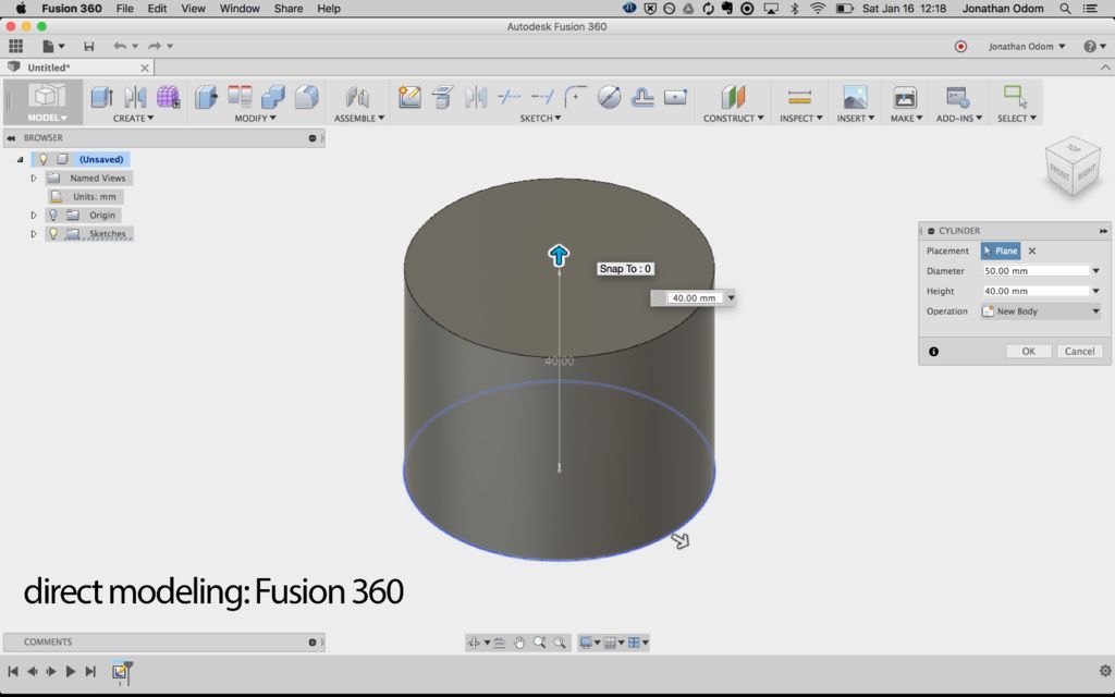
Fusion360 3d print
How to 3D Print from Fusion 360
Once a Fusion 360 model is finished, it is time to get it 3D printed. However, the finished 3D model cannot print as-is. A 3D printer (or CNC Machine) needs a toolpath or “instructions” to create the model. Instructions are typically in the form of a G-code (.gcode) file. A 3D Printer’s “slicer” must be used to convert the STL file to G-code. Here are three ways to get your 3D model from Fusion 360 and retrieve G-code.
Save As Mesh
Saving an STL (Standard Tessellation Language) file from Fusion 360 is one of the easiest ways to transfer models from Fusion 360 to a 3D printing slicer. This format uses a series of linked triangles to recreate the surface geometry of the 3D model. Use STL files because they are small in size and easy to transfer to 3D machines and software. STL files can also be uploaded and shared with others via online sites like Thangs and Thingiverse.
Exporting STL from Fusion 360
In Fusion 360, right-click on the root (top-level) component, a component, or a 3D body in the Fusion 360 Browser.
Then, select “Save as Mesh” from the right-click menu. This opens the Save as Mesh Fusion 360 dialog, where we can define the export settings.
3D Print from Fusion 360 using the Save as Mesh selection.Format: We recommend 3MF files over STL files because they include units of measure and some additional metadata.
The Binary option is recommended if you prefer STL files, as it creates a smaller file that is easier to use, share, and store. Both Binary and ASCII will use the same number of triangles and quality, so the smaller file is preferable.
3D Printing: STL files are unitless, so it’s critical to know what unit of measurement the Slicer of software program will expect. See Why is STL 10 times larger than expected.
Structure: If you are printing a model which is already arranged per the print, then the structure should be set to one file. If the model will be arranged as individual parts, then One File per Body will save each body as an individual STL, saving some time by creating multiple files.
Refinement: If the model contains organic shapes and many curves, then a higher refinement may be required, which will increase the number of triangles saved in the STL. This gives the STL higher resolution but increases the file size.
After defining the settings, select OK to save the mesh file.
Importing STL to a Slicer Software
Many 3D printing companies have software that they recommend when using their 3D printers, such as Cura or Prusa Slicer. In addition, slicers often include templates for common makes and models of 3D printers.
After opening your chosen Slicer, click on the import button (or go to File > Import) and select the STL file from your computer.
Select Slice – note that some slicers automatically do this.
Then save the G-code to your computer or an SD card, depending on your printer’s setup.
Send to Print UtilityIf you would like to 3D print immediately – it is possible to skip the STL export by sending it straight to your chosen slicer.
Select Tools in the toolbar (of the Design Workspace), select Make, then 3D Print. The 3D Print feature will open the same dialog as Save as Mesh.
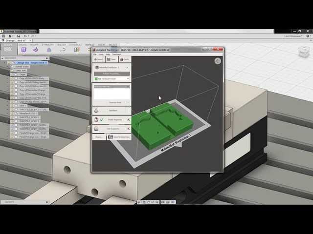
Check the “Send to 3D Print Utility” in the 3D Print/Save as Mesh dialog. Note that the first time you will be required to select the Application from your computer’s folders.
Once you select OK, Fusion 360 will open the Slicer with the part in the print bed. Double-check that your settings are correct before slicing and saving the G-code.
Send to 3D Print Utility allows you to 3D Print Fusion 360 files using your chosen slicer.Slice Directly in Fusion 360Fusion 360 is a CAD/CAM package that helps you quickly go from design to manufacturing. It’s no surprise that they also allow users to set up additive manufacturing files for 3D printing directly in Fusion 360.
This workflow allows users to get the G-code file without the use of external slicers.
Start by switching to the Manufacture workspace. Select the workspaces dropdown in the upper-left, followed by selecting Manufacture.
Select the Additive tab in the toolbar. Then, select the Setup feature, which opens the Setup dialog.
Fusion 360’s Manufacture workspace includes additive functionality to 3D Print from Fusion 360.Machine: Select the 3D printer to be used.
Print Settings: Fusion 360 offers preset settings for each printer. If you don’t find your machine (3D Printer) you can create a custom machine.
Setup: For Operation Type select Additive.
Arrangement: Automatic should be checked.
Model: Select the bodies that are going to be 3D printed.
Select OK.
A new setup has then been created. Right-click on the Additive Toolpath and click generate. There will be a bit of loading, and then you will be able to see how the model is being sliced by selecting Simulate Additive Toolpath.
After defining your print settings, select “Post Process,” then Post. This will allow you to save the G-code to your computer.
Here is an in-depth step-by-step tutorial on Slicing directly in Fusion 360: https://www.youtube.com/watch?v=E6hFaC6dDlM
Save as Mesh (STL) Summary
STL files are the most common file for 3D printing due to their file size and wide acceptance from 3D printer slicers. STL files are small in size and a storage-friendly way to transfer models between different users.
In Fusion 360, sending your model to 3D Print Utility is a quick way to send the 3D model to a slicer without the need to export an STL file. This streamlines the workflow and prevents clutter in your computer storage.
Using Fusion 360’s built-in slicer is a great way to maximize efficiency, allowing you to automatically update toolpaths after making critical design updates.
Tips to Prepare Your Design for 3D Printing
Autodesk’s Fusion 360 is a versatile CAD package that has all the features needed to develop products from the conceptual phase through design verification to manufacturing on both traditional and digital fabrication tools like 3D printing.
In this in-depth Fusion 360 3D printing tutorial, you’ll find a quick overview of Fusion 360’s interface and features for 3D printing as well as detailed tips to help you prepare parts for 3D printing.
Webinar
In this webinar, dive deep into the brand new Formlabs-specific workflows built into Fusion 360. This integration makes it easier than ever to make downstream design changes with a seamless connection between design and manufacturing.
Watch the Webinar Now
Fusion 360 is a cloud-based CAD platform that is an affordable, highly capable alternative to other major players in the industry. It is easy to use and has all the common features you can expect from popular CAD packages. Fusion 360 was built from the ground up to be an all-encompassing product development solution and aims to offer a simple workflow from conceptual design all the way through manufacturing.
Fusion 360 has a very large knowledge base that thoroughly covers every feature of the software, these tutorials can be accessed through Fusion 360 as well as through the Autodesk website. There is also an official YouTube channel with many hours of free tutorials.
The software receives frequent upgrades and new features arrive every few months. Fusion 360 is ideal for high turnover businesses as well as start-ups looking for a professional tool to get them into the market.
Fusion 360 can perform resource-intensive operations on the cloud, including rendering, simulation, shape optimization, and generative design. This means that work can continue while all the heavy lifting is done on the cloud.
There are various licensing packages available, these are listed below:
- Free Trial: Autodesk offers a 30-day free trial upon signup.
- Educational: Like most other CAD packages, Fusion 360 comes with an educational license to students, educators, and academic institutions.
- Start-up: A free license is available for start-ups, enthusiast, and hobbyist. In order to use this license, the user must run a company that has a turnover of less than $100 000 per year.
 The start-up license does not include any of the more advanced features such as generative design.
 - Commercial: There used to be two versions of the paid license, namely a standard and ultimate, but these have been merged into one version that contains all the features that used to be in the ultimate version. The fees are structured as a subscription model.
In Fusion 360, you can switch between seven different workspaces. Each workspace has its own set of tools and functions:
- Design: For drawing 3D models and surfaces by making use of sketches, extrusions, revolves, and many other standard CAD tools.
- Generative Design: Generative Design is a form of artificial intelligence that leverages the power of the cloud and machine learning to output efficient design iterations based on your mechanical constraints.
- Render: Create photorealistic renderings of components and products.
- Animation: Animate assemblies to see if they function as expected or to show functionality to prospective clients.
- Simulation: Computer-aided engineering to perform various stress analyses on the designs to make sure they can handle the operating conditions.
- Manufacture: Computer-aided manufacturing (CAM) to assist with manufacturing the part on various digital fabrication tools, such as CNC mills, CNC lathes, laser cutters, and waterjet cutters.
- Drawing: Create shop drawings of designs for manufacturing in a traditional manual machine shop or to accompany the G-code for CNC machined parts.
The Fusion 360 workspace is divided into seven main sections, namely the tool bar, data panel, navigation, timeline, browser, view cube, and the marking menu. Each of these is described in more detail below.
The toolbar contains all the tools and features that are available in a workspace. In the case of the design workspace, these tools help create and modify 3D models, surfaces, sheet metal, and assemblies.
The data panel allows the user to open existing projects, create new ones, manually save a project and access the data panel. The data panel is a space where designs can be saved and organized in an easy to navigate format. The data panel allows you to create project folders as well as a place to find sample parts and tutorials.
The navigation bar contains all the tools for rotating, translating and changing the visual style of a model. There are also options to break the canvas into subsections with each indicating a different view of the model.
The timeline shows a history of all the operations performed to create the part. This includes all features, patterns, material changes, and sketches to name a few. This is a unique feature that allows you to see the complete history of their part without having to navigate through the browser tree. Any feature can be modified with a right-click within the timeline.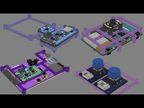 The timeline can also be used to find that specific feature in the browser tree.
The browser contains all the components, features, bodies, sketches, and construction geometry of a design. The browser takes the form a tree-like structure which should be familiar from common CAD packages.
The view cube allows you to manipulate the model in a more structured way. By clicking either on the corners, edges, or faces of the cube the model will re-oriented inside the canvas. This makes it easy to switch between standard views. If the user clicks the arrow on the bottom right of the view cube, a drop-down menu appears that provides more options to control the view.
The marking menu is a situation specific pop-up menu that contains commonly used features, it can be accessed by clicking right on the model or the canvas. The features that show up in the menu are determined by what is clicked and what workspace is currently active. This menu helps increase modeling speed and convenience.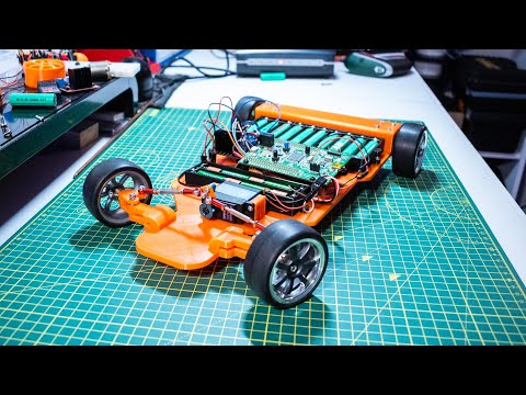
Webinar
In this webinar, Formlabs Product Marketing Lead Jennifer Milne will provide a simple overview explaining what generative design is, framed in a way that is applicable to mechanical part design, including a step-by-step tutorial of Fusion 360 where she’ll produce a lightweight bracket.
Watch the Webinar Now
Formlabs and Autodesk have partnered to streamline your digital workflow with introducing new functionality in Fusion 360 for 3D printing your designs with SLA and SLS technologies from Formlabs. Our Form 2, Form 3+, Form 3B+ and Form 3L SLA 3D printers and the Fuse 1+ 30W SLS printer are included in the Machine library for Fusion 360. This new workflow combines the best of Autodesk’s versatile CAD package with professional 3D printing results. We’re excited to bring this new functionality to Formlabs users, who can now iterate on new ideas in just a few steps.
The software integration includes a brand new graphic interface where users can visualize how parts will fit into the build volumes of the different printers natively in Fusion 360.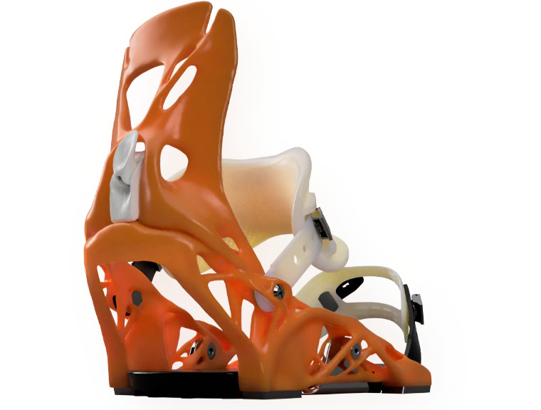 Individual designers can orient their parts, arrange them within the build platform and automatically generate support structures parametrically all within the manufacturing workspace of Fusion 360. If they need to make a design change, their print preparation operations update automatically. Teams can also streamline file management by exporting their build platform as a “.form” file from Fusion 360 and open them in PreForm. Soon additive manufacturing setups created in Fusion 360 will be sent directly PreForm as well. This new integration eliminates the need to save individual parts as “.stl” files and importing them to PreForm manually, giving designers and manufacturers more reliable version control.
Sample part
See and feel Formlabs quality firsthand. We’ll ship a free sample part to your office.
Request a Free Sample Part
The form feature, denoted by a purple cube, allows the sculpting of complex organic shapes.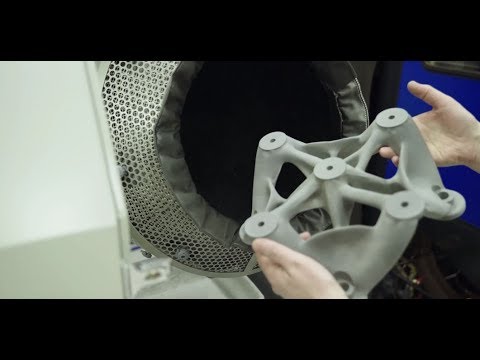 It opens a new workspace that has a wide array of features for sculpting complex shapes. This feature is ideal for creating organic and artistic models for 3D printing.
The surface tools allow the user to repair models for 3D printing. Surfaces can be stitched closed, extruded, pulled, and pushed to reshape the part. The surfacing tools also help create a watertight model that has no openings in the shell.
This feature is useful for simulating how your 3D print will behave under time dependant loads and velocities. For example, snap fit joints can be modeled to show what loads are experienced by the clip as it is forced closed, providing a good idea of where the weak points are so that the design can be optimized.
Some 3D printing technologies like fused deposition modeling (FDM) create parts with non-linear material properties that can only be simulated if the FEA package has a non-linear study type. Fusion 360 features a very capable non-linear study type that can accurately predict the stress on a component provided the correct material data is loaded in.
Find out more about isotropy in 3D printing.
Webinar
In this session, Peter Deppe of KUHMUTE discusses how he leverages Fusion 360 with 3D printing to reduce costs, iterate quickly, and manufacture bespoke solutions for customers.
Watch the Webinar Now
Designing for 3D printing is not an overly complex task, however, there are a few general guidelines to ensure a perfect print every time.
First, consider the 3D printing technology that will be used to print the part(s). This will determine the type of design constraints, the levels of accuracy achievable, and support structure requirements
Learn more about the three most established technologies for 3D printing plastics today—stereolithography (SLA), fused deposition modeling (FDM), and selective laser sintering (SLS)—in our comprehensive guide.
Wall thickness is critical because parts with too thin walls will be brittle and might break during 3D printing or in post-processing. The minimum recommended wall thicknesses vary by printing technology.
Download the Formlabs design guide for stereolithography 3D printers.
Overhangs are easy to print on SLS 3D printers, as the material is supported by the unfused powder. Other technologies like SLA or FDM might require support structures for overhanging features.
Depending on the technology, printing large solid or flat components can result in warping due to the heat build up in the part. Add design features like ribs to make the design structurally stronger and help minimize warping.
Read our guide for ten insights to help you optimize your 3D printing rapid prototyping workflow to be as cost and time efficient as possible.
Clicking the Make icon in the Design workspace opens the 3D print menu to make a number of modifications to optimize the model for printing and then send the model to a 3D print utility.
The menu is broken down into a number of options as listed below:
This option allows the user to select the model for 3D printing.
This checkbox shows the mesh on the model that is useful if the user wants to see what effect changes in the settings have on the model.
This shows the number of individual triangles that make up the model. A higher refinement will increase this number.
This option allows you to select one of three pre-defined refinement settings: low, medium, and high. This determines the total number of triangles used in the model. There is also a custom option which allows the user to further refine the mesh based on specific parameters:
Fusion 360 allows you to send the model to a range of 3D print utilities such as Meshmixer or Formlabs PreForm for 3D printing.
Use PreForm software to prepare parts for 3D printing on Formlabs SLA 3D printers.
If the “Send to 3D print Utility” is not selected Fusion 360 will export the model as an STL file according to the refinement options selected. This STL file can then be loaded into any 3D printer slicer software.
Fusion 360 is a versatile CAD package with an array of features that makes it easy to connect digital workflows and move from design to manufacturing.
Looking for the right tool to turn your design into reality? 3D printers empower engineers and product designers to rapidly prototype in-house, saving time and costs at every stage of product development.
See the quality firsthand by requesting a free sample part printed on a Formlabs 3D printer.
Explore Formlabs 3D PrintersRequest a Free Sample Part
3D CAD reinvented - Fusion 360
Fusion 360
from idea to finished product
Consolidate all project development processes into a single
software product.
Buy Fusion 360 Try for free
Build Complex Products Easily
Fusion 360's One Solution Now Includes All Ultimate Features, Including:
- Generative Design
- Advanced engineering analysis
- Simultaneous 4- and 5-axis machining
Demo version
Watch video
Functionality
CAD: Design
Determine the shape and design features of the future product, using the maximum available number of actual types of modeling: spline, surface, solid, parametric and direct.![]() Work in an environment that supports the import of more than 50 file formats, and does not burden your computer due to the use of cloud technologies.
Work in an environment that supports the import of more than 50 file formats, and does not burden your computer due to the use of cloud technologies.
More
CAE: Engineering Analysis
Work out the engineering component of your project. Calculate the product for strength, conduct a modal or thermal strength analysis. Determine how the dynamic movement of the moving parts of the assemblies will be carried out. Prepare photorealistic images of the project and animation.
More
CAM: Production
Get your product ready for production: use automated CNC programming tools (up to 5 axes) or 3D printers. Create a drawing of the future product and, if necessary, export it for revision in AutoCAD. Provide access to the finished project for the manufacturer from anywhere in the world.
More
1
3D Design & Design
Don't let your design tool limit your creativity and ability to quickly create multiple design iterations.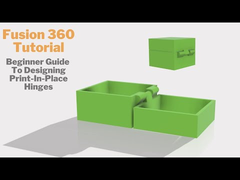 Design the way you want at all stages of the product development process.
2
Electronics
Stop fighting with outdated design methods and file formats. Get all the benefits of a full-featured electronic design and mechanical CAD tool in a single platform.
3
Simulation
Don't wait. Test your designs early in development to determine usability and identify weaknesses early.
4
Generative Design
Expand your ability to innovate. Generate many high quality designs based on a range of manufacturing and material constraints. After selecting the appropriate option, you can edit it in CAD.
5
Technical documentation
Forget export. Prepare technical documentation directly from 3D models for maximum manufacturing accuracy.
6
Collaboration
Don't let location, time zones, and lengthy coordination drag out the development process. View all project data in a single project dashboard and easily collaborate with colleagues around the world.
7
Manufacturing
Avoid costly rework, product defects and deadlines that affect your bottom line. Use HSM technologies to produce high quality CNC machined parts and additive manufacturing structures using FFF or PBF for 3D metal printing.
Project Gallery
View all projects
TRY FUSION 360 NOW
Download a free 30-day trial of Fusion 360 and experience all the features of this unique product.
Or purchase a one or three year subscription.
Buy Fusion 360
Demo version
Useful resources
Here are some useful resources that will help you work with Fusion 360.
Also, you can ask our specialists any question about the functionality and purchase of Fusion 360. We will definitely help you as soon as possible!
Fusion 360 Training
Educational videos
Forum
Blog
Public offer |Personal data processing policy
Start printing directly from Fusion 360
Although many people are skeptical about the slicing functionality in Fusion 360, I have only been using it since its release (I think March 2020). In the next few articles, I want to tell you exactly what you need to do in order to get the G-code of your model directly from the fusion.
In the first part, I will outline the algorithm of actions for generating code in large blocks. Then we will do an interactive stream, and after that there will be one or more articles detailing the incomprehensible steps.
First, the model itself is needed. We assume that the part is already made, saved in one of the projects in the cloud and ready for printing.
Next we have to go into Manufacture mode, just click on Design and select Manufacture there. We will find ourselves in a new mode of operation with the same model.
Once again, an important thought - the model does not change, it is not transferred / uploaded / exported anywhere. The geometry remains the same, we just change the mode of working with it and the tools.
Cool fact #1 - printing from fusion makes it possible not to export / import the model, we do not divide the model into the stages "solid state for editing", "stl for printing". Within the same system, we work with the same model with different tools.Simply switch between Design/Manufacture modes and accordingly alternately get model editing tools and code generation tools
After switching to Manufacture, the concept Setup becomes key for us. This thing is well known to those who work on CNC machines, and we also have to deal with it.
When we prepare the print, in the setup we need to put together the following information: we set it by creating in the library (once) and then selecting (each time when creating a setup) our printer ( Machine ).
For other CNC systems, the Machine setting is optional, but for printing (that is, additive operations) it is critical. All machine descriptions are stored in the library. The car needs to be created in advance, before creating the first setup, but next time you can just select it from the library.
The following is written in the machine:
- the number and parameters of extruders
- the presence of model airflow
- table dimensions
- where to park the head after printing
- and, of course, the name and text description
In general, everything that describes the printer geometrically and gives an idea of its maximum capabilities.
A good practice to create your own car is to (1) take one of the already prepared descriptions (2) copy it to your library and (3) fix it to your needs.
The library, for example, already has Ender 3. If your printer is not there, then just copy the default " Autodesk Generic FFF Machine ".
In my case, the set of edits was minimal - table dimensions, parking coordinates and description.
The second part of the setup, "what to print" - is indicated in paragraph Model and there you can select the entire model, component (or several)
Important fact #2 - if you are printing a multi-part model, you need to make sure that each part is in its own component.If this is not done, then fusion will work with the entire group as with one part and you will not be able to lay out individual parts on the table.Positioning tools - Move, Arrange, Automatic Orientation and Place part on platform work only with 9 components0154And finally, the third part of the setup, "with what settings to print" - this is called Print Settings and this thing is very similar to Machine in organization:
- they also need to be done in advance, before creating the setup
- they are also stored in the library
- you can also take them from the default ones, copy them to yourself and fix them
- you can also create as many as you need and then just select from the library
All print settings are stored in print settings:
- temperatures
- speed
- or not (and which ones) - BRAM, SKIRT, RAFT, Support
- Perimeters settings, filling
- and so on, and so on
Important fact #3 - PRINT settings can be changed directly inside the setup, these changes only affect the current setup.For example, you have an ABS profile with temperatures/speeds, but in this model you want the speeds to be different - you can easily change the settings after creating the setup and do not spoil the profile stored in the library
In total, when you put all three parts together and created a setup, you get this element
After that, you shamelessly use all the available tools for positioning parts, among which there is a wonderful Automatic Orientation, which I will talk about someday later
You can change the print settings for this setup as you like, without fear of damaging the saved profiles
And most importantly, you must do two things.
First, generate an extruder path ( toolpath ) for a given setup (i.e. machine + model + settings) process (3) trajectory is ready
Naturally, this procedure must be done every time you change something in the settings or setup. The rule is very simple, we see an exclamation mark - it means we need to regenerate the trajectory.
And the second important thing - you check the received trajectory in the built-in simulator. P-time:
Two:
Remarkable fact #4 - you can create as many setups for your model as you like. This may be necessary, for example, if you print different parts with different settings, I do this when some need to be printed with supports, and some without. We simply create a new setup, select only those components in it that should fall into it and set our own settings in the setupWhen you have visually got what you need, only one step separates you from the G-code - post-processing .
The point is that the toolpath you see is not code yet. These are geometric lines, displaying the movement of the extruder, but not the code. The code is generated by a postprocessor, which is essentially a JavaScript program (but you don't need to understand these subtleties at all).
So, post-processing. When the toolpath is ready and you are satisfied, do this
Then like this:
Then like this
And that's it.
Press Post, show where to put the file, save. The code is ready.
In a nutshell, what we just did:
- select the library of pre-installed post processors
- select the default "Generic FFF Machine" post from it
- upload the code through this post processor
This whole process can be made easier, faster, better, etc. - you can make your own postprocessor and put it in your own library; you can specify in the Machine settings which post to use for your printer and where exactly to put the files with the code. And so on.
There are a lot of opportunities to flexibly bend the process to your liking.
After creating all the setups and settings don't forget to save, because there is
Cool Fact #5 - fusion printing makes it very easy to iterate. After creating the setups and checking the settings, we can switch to Design mode and edit the model. After returning to Manufacture, we just need to click Generate toolpath to get new toolpaths for the modified model.
Learn more