Fusion 360 export to 3d printer
How to 3D Print from Fusion 360
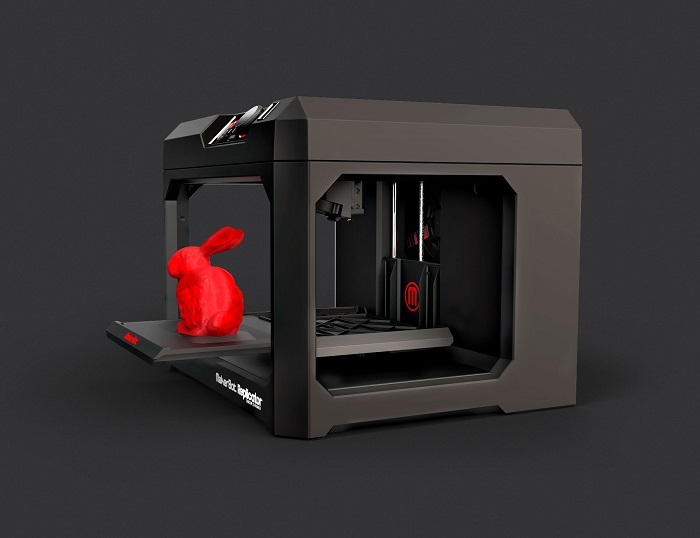
Once a Fusion 360 model is finished, it is time to get it 3D printed. However, the finished 3D model cannot print as-is. A 3D printer (or CNC Machine) needs a toolpath or “instructions” to create the model. Instructions are typically in the form of a G-code (.gcode) file. A 3D Printer’s “slicer” must be used to convert the STL file to G-code. Here are three ways to get your 3D model from Fusion 360 and retrieve G-code.
Save As Mesh
Saving an STL (Standard Tessellation Language) file from Fusion 360 is one of the easiest ways to transfer models from Fusion 360 to a 3D printing slicer. This format uses a series of linked triangles to recreate the surface geometry of the 3D model. Use STL files because they are small in size and easy to transfer to 3D machines and software. STL files can also be uploaded and shared with others via online sites like Thangs and Thingiverse.
Exporting STL from Fusion 360
In Fusion 360, right-click on the root (top-level) component, a component, or a 3D body in the Fusion 360 Browser.
Then, select “Save as Mesh” from the right-click menu. This opens the Save as Mesh Fusion 360 dialog, where we can define the export settings.
3D Print from Fusion 360 using the Save as Mesh selection.Format: We recommend 3MF files over STL files because they include units of measure and some additional metadata.
The Binary option is recommended if you prefer STL files, as it creates a smaller file that is easier to use, share, and store. Both Binary and ASCII will use the same number of triangles and quality, so the smaller file is preferable.
3D Printing: STL files are unitless, so it’s critical to know what unit of measurement the Slicer of software program will expect. See Why is STL 10 times larger than expected.
Structure: If you are printing a model which is already arranged per the print, then the structure should be set to one file. If the model will be arranged as individual parts, then One File per Body will save each body as an individual STL, saving some time by creating multiple files.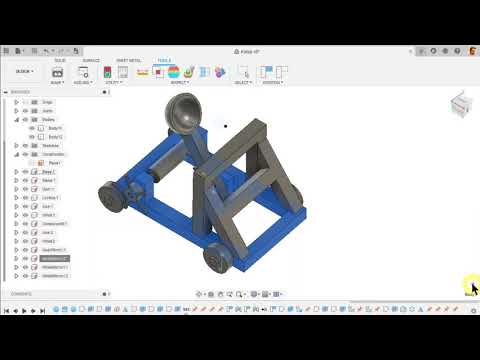
Refinement: If the model contains organic shapes and many curves, then a higher refinement may be required, which will increase the number of triangles saved in the STL. This gives the STL higher resolution but increases the file size.
After defining the settings, select OK to save the mesh file.
Importing STL to a Slicer Software
Many 3D printing companies have software that they recommend when using their 3D printers, such as Cura or Prusa Slicer. In addition, slicers often include templates for common makes and models of 3D printers.
After opening your chosen Slicer, click on the import button (or go to File > Import) and select the STL file from your computer.
Select Slice – note that some slicers automatically do this.
Then save the G-code to your computer or an SD card, depending on your printer’s setup.
Send to Print UtilityIf you would like to 3D print immediately – it is possible to skip the STL export by sending it straight to your chosen slicer.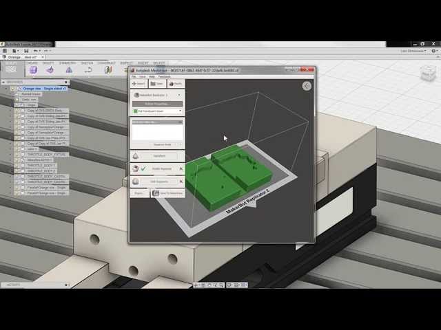
Select Tools in the toolbar (of the Design Workspace), select Make, then 3D Print. The 3D Print feature will open the same dialog as Save as Mesh.
Check the “Send to 3D Print Utility” in the 3D Print/Save as Mesh dialog. Note that the first time you will be required to select the Application from your computer’s folders.
Once you select OK, Fusion 360 will open the Slicer with the part in the print bed. Double-check that your settings are correct before slicing and saving the G-code.
Send to 3D Print Utility allows you to 3D Print Fusion 360 files using your chosen slicer.Slice Directly in Fusion 360Fusion 360 is a CAD/CAM package that helps you quickly go from design to manufacturing. It’s no surprise that they also allow users to set up additive manufacturing files for 3D printing directly in Fusion 360.
This workflow allows users to get the G-code file without the use of external slicers.
Start by switching to the Manufacture workspace.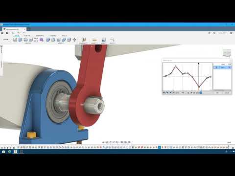 Select the workspaces dropdown in the upper-left, followed by selecting Manufacture.
Select the Additive tab in the toolbar. Then, select the Setup feature, which opens the Setup dialog.
Fusion 360’s Manufacture workspace includes additive functionality to 3D Print from Fusion 360.Machine: Select the 3D printer to be used.
Print Settings: Fusion 360 offers preset settings for each printer. If you don’t find your machine (3D Printer) you can create a custom machine.
Setup: For Operation Type select Additive.
Arrangement: Automatic should be checked.
Model: Select the bodies that are going to be 3D printed.
Select OK.
A new setup has then been created. Right-click on the Additive Toolpath and click generate. There will be a bit of loading, and then you will be able to see how the model is being sliced by selecting Simulate Additive Toolpath.
After defining your print settings, select “Post Process,” then Post.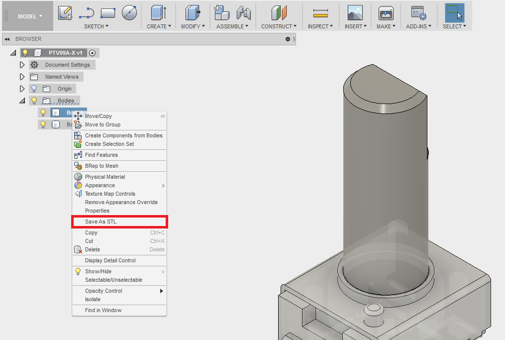 This will allow you to save the G-code to your computer.
Here is an in-depth step-by-step tutorial on Slicing directly in Fusion 360: https://www.youtube.com/watch?v=E6hFaC6dDlM
Save as Mesh (STL) Summary
STL files are the most common file for 3D printing due to their file size and wide acceptance from 3D printer slicers. STL files are small in size and a storage-friendly way to transfer models between different users.
In Fusion 360, sending your model to 3D Print Utility is a quick way to send the 3D model to a slicer without the need to export an STL file. This streamlines the workflow and prevents clutter in your computer storage.
Using Fusion 360’s built-in slicer is a great way to maximize efficiency, allowing you to automatically update toolpaths after making critical design updates.
How to Export STL Files For Best 3D Print Quality - Fusion3
EXPORTING STL FILES FOR BEST 3D PRINTING QUALITY
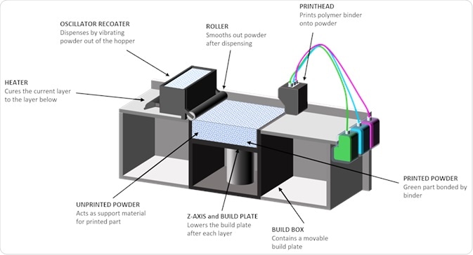
UNDERSTANDING THE STL FORMAT
A traditional CAD (computer aided design file) uses a series of coordinates and formulas to represent the shape of your 3D object.
However, the .STL format is a bit different. It uses a series of triangles to generate a ‘mesh’ of the surface of your 3D part.
.STL can perfectly replicate a 3D model made up of flat surfaces.
If your model is made up of curves, the .STL file is only making an approximation of your object. This is why the quality of the amount of detail in your exported file is important for the quality of your 3D print.
Two concentric circles, representing a CAD model of a doughnut shape, and a series of triangles approximating the doughnut, representing how STL modeling works. (Source: Wikipedia)
STL file in Fusion3 REACTOR showing too few curves when exported. Note how the rounded surface shows as a series of rectangular bevels.
EXPORTING YOUR CAD FILE WITH TOO FEW POLYGONS
If you export the file with too few polygons, the model will have visible flaws on its surface when printed.
This will most likely appear either as triangles on a rounded surface or rectangular bevels on a curved
EXPORTING YOUR CAD FILE WITH TOO MANY POLYGONS
The reaction by most people is to export the file with as many polygons as possible. This is also not recommended.
The FDM 3D printing process likely cannot recreate this level of detail. The larger file size and details may cause the slicer software to either:
- Work much more slowly or freeze
- Cause errors for either the printer or software as it attempts to handle levels of detail beyond its capability.
EXPORTING YOUR CAD FILE WITH THE RIGHT AMOUNT OF POLYGONS
As with Goldilocks and the three bears, there is a “just right” level of detail for 3D printing.
This amount of detail provides an amount of polygons sufficient for a 3D printer of the F410’s caliber to be able to create the part in high detail, but not overwhelm the printer’s software.
As shown in the image on the right, rounded shapes appear smooth with a minimum of faceting.
In each of the sections below, we at Fusion3 provide you with a compilation of optimized settings for exporting .STL files with each of the major CAD programs.
.STL file in Fusion3 REACTOR showing sufficient number of polygons to render the curve without overwhelming the software. The rounded surface now appears smooth.
EXPORTING STL FILES FROM SOLIDWORKS FOR BEST 3D PRINTING QUALITY
Most Fusion3 customers use SolidWorks. In the past, SolidWorks’ STL export filter using the “FINE” preset would generate excellent output. However, recently (as of January, 2021), we have found the level of detail to still be inadequate and below the level of detail our 3D printers are capable of.
Here are our recommended settings for exporting an STL file from SolidWorks for 3D printing on a Fusion3 3D printer (and accompanying screen shot):
File Format: STL
Output as:
a. ASCII
b. Unit: Millimeters
Resolution:
a. Custom
b. Deviation: Tolerance 0.09584862mm
c. Angle 3.500 deg
d. Show STL info before saving
e. Define Maximum Facet Size (unchecked)
f. Preview Before Saviing File (unchecked)
Do no translate STL output data to positive space: (unchecked)
Save all components of an assembly in a single file: (unchecked)
.STL file in Fusion3 REACTOR showing sufficient number of polygons to render the curve without overwhelming the software. The rounded surface now appears smooth.
EXPORTING STL FILES FROM AUTODESK INVENTOR FOR BEST 3D PRINTING QUALITY
- Before finalizing your export, select the Options tab.
- Select “High” resolution (faceting) for your model (High, Medium, Low and Custom) and check that your units are correct. The “High” setting will produce a large file size. Autodesk Inventor allows you to save both individual parts and assemblies in STL format, at all design levels.
- Check your modifiers have been applied before exporting:
Tools > Rebuild All (this ensures that the design data contains recent changes, and that it is not corrupt)
File > Save Copy As > STL (.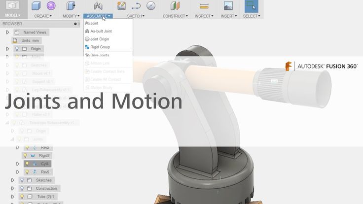 stl)
stl)
Select High and click OKNote: To change the values associated with each of the resolution settings (High/Medium/Low) you need to edit the Windows registry.
Select IPro > Print > 3D Print Preview - Select Options and choose desired resolution and click OK.
- Within the preview window, select Save Copy As or Send to 3D Print Service
- Save As type to STL File (*.stl)
EXPORTING STL FILES FROM AUTODESK FUSION360 FOR BEST 3D PRINTING QUALITY
Step 1.
Right click on a body in the workspace browser.
Select the “Save As STL” Command.
Step 2.
Apply your settings to the body per the settings below.
Format: Binary
Structure: One File
Preview Mesh: Checked
Number of Triangles: (Calculated)
Refinement Options: High
Surface Deviation: .004479mm
Normal Deviation: 10.00
Maximum Edge Length: 89.58237mm
Aspect Ratio: 21.50
EXPORTING STL FILES FROM ONSHAPE (PTC) FOR BEST 3D PRINTING QUALITY
STL Format: Binary
Angular Deviation: 1 Degree
Chordal Tolerance: 0. 1mm (0.004″)
Minimum Facet Width: 0.1mm (0.004″)
EXPORTING STL FILES FROM NX (SIEMENS) FOR BEST 3D PRINTING QUALITY
Output File Type: Binary
Chordal Tolerance: 0.1mm (0.004″)
Angular Tolerance: 1 degree
EXPORTING STL FILES FROM CREO (PTC) FOR BEST 3D PRINTING QUALITY
Creo has a parameter called ‘Angle Control’ that doe not adjust the maximum angular deviation in degrees. Instead, this is a measure of angular deviation beyond the radius that would be created by the ‘Chord height’ (chordal tolerance) parameter.
The ‘Angle control’ parameter value can range from 0.0 to 1.0.
Here are a set of settings we suggest as a starting point:
STL Format: Binary
Chord height: 0.1 mm (0.004″)
Angle Control: 0.25
Maximum Edge Length: Default
Aspect Ratio: Default
CLICK TO REQUEST SAMPLE
Autodesk Fusion 360 Export STL Files
With Autodesk Fusion 360, you can easily export your 3D model STL files and prepare them for slicing, especially after reading this handy guide!
Fusion 360 is an incredibly smart and user-friendly computer-aided design (CAD) and computer-aided manufacturing (CAM) program that streamlines and combines the functionality of traditionally separate programs into one application.
You have bought a 3D printer for your home or business and now you are faced with the task of exporting files to STL format - the most convenient format for 3D printing
Fusion 360 provides an intuitive and convenient environment for complex 2D and 3D projects, as well as tools to analyze and prepare these designs for production or rapid prototyping, including access to the Autodesk 360 cloud. Fusion 360 includes easy-to-use tools for preparing models for 3D printing, making it a great companion for anyone using 3D printing for the manifestation of digital projects, whether for rapid prototyping or just for fun. One such tool is the ability to create custom 3D model meshes and export them to STL files for slicing.
There are several ways to export 3D designs as STL mesh files in Fusion 360. These methods depend on whether you want to export single components or solids, an entire model, or multiple solids at once.
Export Entire Design
If you want to export the entire design, including all of its bodies and components, you can do so using the Model Browser tree on the left side of the screen. Right-click on the top branch of the tree and select "Save As STL" from the drop-down menu that appears.
After selecting this option, a small panel will appear on the right side of the screen, in which you can adjust the grid settings. You can also toggle the option to send the file directly to a 3D printing utility such as Cura, Meshmixer, or PreForm.
When prototyping on a 3D printer, we often use Fusion 360 to correct and prepare models for 3D printing.
Exporting Single Components or Solids
To export a single component or solid, simply right-click on the component and select "Save As STL" from the drop-down menu. This action will open the same panel where you can adjust the grid settings. In this window, you can also change the selection of the component or body.
Alternatively, you can select "3D Print" from the "Make" menu in the toolbar at the top of the screen to open the same panel. From here you can select the component or body you want to export.
Export multiple bodies to a single STL file
If you want to export multiple bodies as a single STL mesh file, you can do so by creating a single component containing all the bodies you want to include.
To do this, first create a new component by clicking "New Component" from the "Create" menu in the toolbar. A panel will open on the right side of the screen, prompting you to select one or more solids from the design. Make sure the "From Bodies" option is enabled, select only one body, and then select "OK".
After creating a new component, it will appear at the bottom of the browser tree on the left. To add an additional body to this component, simply find the bodies in the tree and drag them to the new component branch in the tree.
You can then right-click on that component and select "Save as STL" from the drop-down menu to open the "Save as STL" panel. In the panel, you will now see the "Structure" option to create one file for the entire component or create a separate file for each body.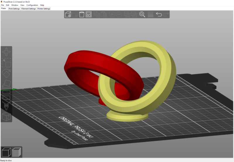 Make sure "One File" is selected and you should be good to go.
Autodesk Fusion 360 - features, full description
CAD: Design
Spline Modeling
Create ergonomic shapes with T-spline and surface modeling technology. Specify the exact shape of the curvature of surfaces, or directly edit the faces, edges, and vertices of splines manually. Fusion 360 subsequent update of the structure. Use familiar top-down and bottom-up design tools such as extrude, revolve, fillet, loft, booleans, and more to create both organic shapes and detailed mechanical products.
Parametric modeling
Use parametric dimensions when defining sketches. This will allow you to associate the geometric characteristics of the elements with a certain value or function. Moreover, when one or another parameter is updated, the model will be automatically updated, respectively, changing the associated elements.
Using mesh models
Import STL and OBJ files scanned from a real object and use them as a base for a future 3D model. Create a spline surface that follows the mesh profile using the Object Snap tool or use the Pull command to snap the spline vertices to the mesh surface. After that, you can proceed to further refine the model.
Standard Component Libraries
Fusion 360 comes with a library of standard engineering parts that meet ISO, ANSI, DIN, and more. zero.
CAE: Engineering Analysis
Engineering Analysis
Understanding how a product will perform in a real environment before it goes into production can save you time and money. Use engineering analysis tools to identify the most vulnerable areas of a future product and fix them at the design stage. Share the results of your calculations with the rest of the team using Fusion Team. At the moment, strength and modal analysis, heat transfer and fatigue strength calculations are available.
Import/Export Files
Import over 50 different CAD formats including SLDPRT, SAT, IGES, STEP, STL and OBJ. Fusion 360 will save the original file and create its own complex F3D format from it. Export files to your local computer or to the cloud - as soon as the model is exported and ready for download, you will receive an e-mail notification. Local export includes IGES, SAT, SMT, STEP, F3D and DXF formats. Cloud export includes Inventor, IGES, SAT, SMT, STEP, DWG, DXF, STL, FBX, and F3D.
Working with assemblies
Assemble parts directly in the same environment in which they were modeled. Make the connections of the parts rigid, for example, as they are currently built, or specify a more detailed specifics of the movable connection: rotational, translational, planar, spherical, helical, etc. Specify the limits of movement to achieve exactly the type of connection that should be in reality and immediately preview any kinematic changes.
Motion Study
Find out how an assembly would behave in real life by activating all connections in the Motion Study environment. Establish the order and method of interaction of moving joints and evaluate the final picture of the kinematics. View the dynamic motion animation or play it in reverse.
Render
Create photorealistic renderings with Fusion 360 using the power of Autodesk cloud servers. Take advantage of the huge library of available materials such as translucent plastics, wood, metal, glass and composites. Edit existing materials and customize them for your project. Adjust camera settings such as focal length, depth of field, lighting type and environment.
Animation
Animate your assembly with flexible camera settings, transitions, detail fade in/out, manual or automatic assembly explosion, informative text callouts, and more. Share your animation after exporting it to MP4 video.
CAM: Manufacturing
2, 2.5, 3 and 5 axis CNC machines
Fusion 360 uses the same CAM engine as HSMWorks and InventorHSM™. This allows you to quickly obtain optimal cutter paths that reduce wear on the cutting tool and provide excellent surface finish on the workpiece.