Fusion 360 3d print multiple bodies
How To Export Multiple Bodies In Fusion 360?
Contents
- 1 How do you export multiple bodies in STL Fusion 360?
- 2 How do you make multiple bodies in Fusion 360?
- 3 How do you save a body in Fusion 360?
- 4 How do you merge bodies in fusion?
- 5 Can Fusion 360 export STL files?
- 6 Can Fusion 360 export STEP files?
- 7 What is the difference between bodies and components in Fusion 360?
- 8 What does grounding do in Fusion 360?
- 9 Can we limit the motions of joint in Fusion 360?
- 10 How do I export my Fusion 360 assembly?
- 11 How do you save a component in Fusion?
- 12 How do you convert a mesh to a body in Fusion 360?
- 13 How do you attach objects in Fusion 360?
- 14 How do you duplicate a sketch in Fusion 360?
- 15 Why does Fusion 360 take so long to export STL?
How do you export multiple bodies in STL Fusion 360?
How do you make multiple bodies in Fusion 360?
How do you save a body in Fusion 360?
1. Save Copy As will create a new Fusion design of the individual component.
2. Save as STL will save the component locally to your computer as an STL file.
3. Export will save a copy of the component locally as a new file.
How do you merge bodies in fusion?
1. Click Design > Solid > Modify > Combine .
2. Select the Target Body.
3. Select Tool Bodies.
4. In the Combine dialog, select the Operation:
5. Optional: Check New Component to create a new component from the result.
Can Fusion 360 export STL files?
There are a couple of different ways export a STL file from Fusion 360. To quickly export an STL, perform the following: Right click on the component, component group, or body in the model Browser tree (left panel). Select Save As Mesh.7 juil. 2021
Can Fusion 360 export STEP files?
Good news, Fusion 360 fans — Autodesk just announced that they won’t be removing support for STEP file exports for personal use licensees of the popular CAD/CAM platform after all. 25 sept. 2020
What is the difference between bodies and components in Fusion 360?
Components are the building blocks that make up assemblies, and a body is one of the elements that make up a component. Each component contains one or more bodies, as well as its own set of origin planes, sketches, construction geometry, joints, and other elements.
What does grounding do in Fusion 360?
Grounding locks the origin of the grounded component to the top level origin in that design/file and only there. So an assembly has its own origin. When you ground the assembly its origin it’s fixed.20 août 2019
Can we limit the motions of joint in Fusion 360?
Joint Limits are values that define the range of motion allowed for components that move or rotate in an assembly in Fusion 360. You can use joint limits to evaluate a design by limiting motion to known maximum, minimum, and resting values. … Maximum: Sets the maximum limit on the range of motion.2 juil. 2021
How do I export my Fusion 360 assembly?
1. In Fusion 360, go to File -> Export.
2. Select “Audesk Inventor [] Files (*. ipt, *. iam)” as the export format.
3. Export the assembly.
4. Import the IAM assembly into Inventor.
How do you save a component in Fusion?
Right-click on the component you want to save in the browser and select “Save Copy As”. Then, rename the design and specify the location as required.28 nov. 2016
How do you convert a mesh to a body in Fusion 360?
Select the Model Workspace and then to convert the mesh to a solid body all you’ll have to do is right click on the mesh and select “Mesh to BRep.” You’ll then see in the dialogue box that you can have it create a new body or a new component. Want to learn more about Fusion 360?4 oct. 2018
How do you attach objects in Fusion 360?
How do you duplicate a sketch in Fusion 360?
Why does Fusion 360 take so long to export STL?
Fusion 360 exports STL files locally, so there is no influence of the cloud or internet bandwidth. But your 3D model has to be meshed to export STL. And the mesh granularity (triangle size, density) – if set to very detailed – can make the resulting file huge and slow to produce.
How to 3D Print from Fusion 360
Once a Fusion 360 model is finished, it is time to get it 3D printed. However, the finished 3D model cannot print as-is. A 3D printer (or CNC Machine) needs a toolpath or “instructions” to create the model. Instructions are typically in the form of a G-code (.gcode) file. A 3D Printer’s “slicer” must be used to convert the STL file to G-code. Here are three ways to get your 3D model from Fusion 360 and retrieve G-code.
Save As Mesh
Saving an STL (Standard Tessellation Language) file from Fusion 360 is one of the easiest ways to transfer models from Fusion 360 to a 3D printing slicer. This format uses a series of linked triangles to recreate the surface geometry of the 3D model. Use STL files because they are small in size and easy to transfer to 3D machines and software. STL files can also be uploaded and shared with others via online sites like Thangs and Thingiverse.
Exporting STL from Fusion 360
In Fusion 360, right-click on the root (top-level) component, a component, or a 3D body in the Fusion 360 Browser.
Then, select “Save as Mesh” from the right-click menu. This opens the Save as Mesh Fusion 360 dialog, where we can define the export settings.
3D Print from Fusion 360 using the Save as Mesh selection.Format: We recommend 3MF files over STL files because they include units of measure and some additional metadata.
The Binary option is recommended if you prefer STL files, as it creates a smaller file that is easier to use, share, and store. Both Binary and ASCII will use the same number of triangles and quality, so the smaller file is preferable.
3D Printing: STL files are unitless, so it’s critical to know what unit of measurement the Slicer of software program will expect. See Why is STL 10 times larger than expected.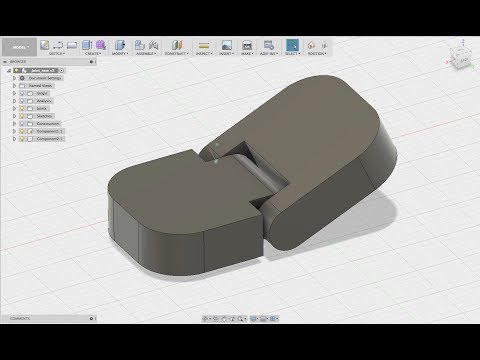
Structure: If you are printing a model which is already arranged per the print, then the structure should be set to one file. If the model will be arranged as individual parts, then One File per Body will save each body as an individual STL, saving some time by creating multiple files.
Refinement: If the model contains organic shapes and many curves, then a higher refinement may be required, which will increase the number of triangles saved in the STL. This gives the STL higher resolution but increases the file size.
After defining the settings, select OK to save the mesh file.
Importing STL to a Slicer Software
Many 3D printing companies have software that they recommend when using their 3D printers, such as Cura or Prusa Slicer. In addition, slicers often include templates for common makes and models of 3D printers.
After opening your chosen Slicer, click on the import button (or go to File > Import) and select the STL file from your computer.
Select Slice – note that some slicers automatically do this.
Then save the G-code to your computer or an SD card, depending on your printer’s setup.
Send to Print UtilityIf you would like to 3D print immediately – it is possible to skip the STL export by sending it straight to your chosen slicer.
Select Tools in the toolbar (of the Design Workspace), select Make, then 3D Print. The 3D Print feature will open the same dialog as Save as Mesh.
Check the “Send to 3D Print Utility” in the 3D Print/Save as Mesh dialog. Note that the first time you will be required to select the Application from your computer’s folders.
Once you select OK, Fusion 360 will open the Slicer with the part in the print bed. Double-check that your settings are correct before slicing and saving the G-code.
Send to 3D Print Utility allows you to 3D Print Fusion 360 files using your chosen slicer.Slice Directly in Fusion 360Fusion 360 is a CAD/CAM package that helps you quickly go from design to manufacturing.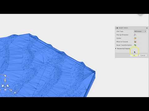 It’s no surprise that they also allow users to set up additive manufacturing files for 3D printing directly in Fusion 360.
This workflow allows users to get the G-code file without the use of external slicers.
Start by switching to the Manufacture workspace. Select the workspaces dropdown in the upper-left, followed by selecting Manufacture.
Select the Additive tab in the toolbar. Then, select the Setup feature, which opens the Setup dialog.
Fusion 360’s Manufacture workspace includes additive functionality to 3D Print from Fusion 360.Machine: Select the 3D printer to be used.
Print Settings: Fusion 360 offers preset settings for each printer. If you don’t find your machine (3D Printer) you can create a custom machine.
Setup: For Operation Type select Additive.
Arrangement: Automatic should be checked.
Model: Select the bodies that are going to be 3D printed.
Select OK.
A new setup has then been created. Right-click on the Additive Toolpath and click generate. There will be a bit of loading, and then you will be able to see how the model is being sliced by selecting Simulate Additive Toolpath.
After defining your print settings, select “Post Process,” then Post. This will allow you to save the G-code to your computer.
Here is an in-depth step-by-step tutorial on Slicing directly in Fusion 360: https://www.youtube.com/watch?v=E6hFaC6dDlM
Save as Mesh (STL) Summary
STL files are the most common file for 3D printing due to their file size and wide acceptance from 3D printer slicers. STL files are small in size and a storage-friendly way to transfer models between different users.
In Fusion 360, sending your model to 3D Print Utility is a quick way to send the 3D model to a slicer without the need to export an STL file. This streamlines the workflow and prevents clutter in your computer storage.
Using Fusion 360’s built-in slicer is a great way to maximize efficiency, allowing you to automatically update toolpaths after making critical design updates.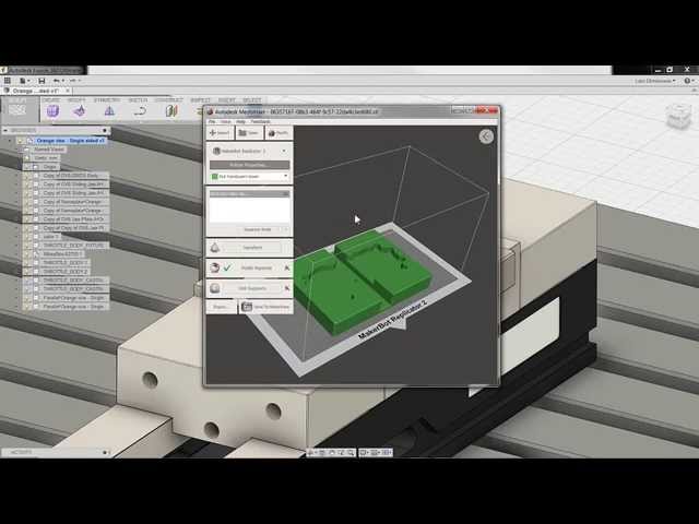
Start printing directly from Fusion 360
Although many people are skeptical about the slicing functionality in Fusion 360, I have only been using it since its release (I think March 2020). In the next few articles, I want to tell you exactly what you need to do in order to get the G-code of your model directly from the fusion.
In the first part, I will outline the algorithm of actions for generating code in large blocks. Then we will do an interactive stream, and after that there will be one or more articles detailing the incomprehensible steps.
First, the model itself is needed. We assume that the part is already made, saved in one of the projects in the cloud and ready for printing.
Next we have to go into Manufacture mode, just click on Design and select Manufacture there. We will find ourselves in a new mode of operation with the same model.
Once again, an important thought - the model does not change, it is not transferred / uploaded / exported anywhere.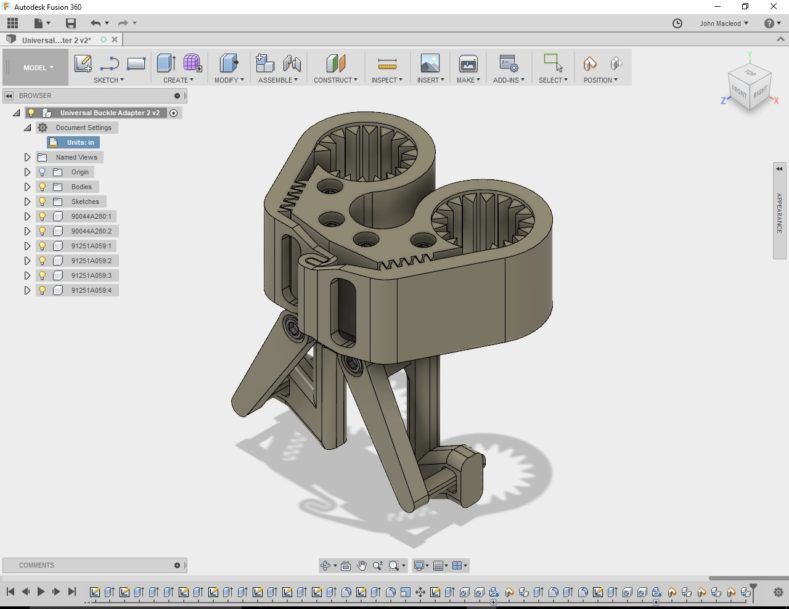 The geometry remains the same, we just change the mode of working with it and the tools.
Cool fact #1 - printing from fusion makes it possible not to export / import the model, we do not divide the model into the "solid state for editing", "stl for printing" stages. Within the same system, we work with the same model with different tools. We simply switch between Design/Manufacture modes and, accordingly, alternately get model editing tools and code generation tools
After switching to Manufacture, the concept 9 becomes key for us0015 Setup . This thing is well known to those who work on CNC machines, and we also have to deal with it.
When we are preparing the print, in the setup we need to put together the following information: we set it by creating in the library (once) and then selecting (each time when creating a setup) our printer ( Machine ).
For other CNC systems, the Machine setting is optional, but for printing (i.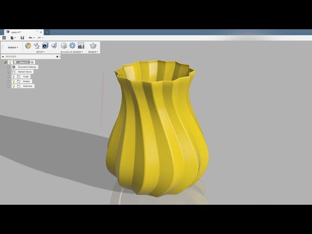 e. additive operations) it is critical. All machine descriptions are stored in the library. The car needs to be created in advance, before creating the first setup, but next time you can just select it from the library.
The following is written in the machine:
- the number and parameters of extruders
- the presence of airflow model
- table dimensions
- where to park the head after printing
- and, of course, the name and text description
In general, everything that describes the printer geometrically and gives an idea of its maximum capabilities.
A good practice to create your own machine is to (1) take one of the already prepared descriptions (2) copy it to your library and (3) fix it to fit your needs.
The library, for example, already has Ender 3. If your printer is not there, then just copy the default " Autodesk Generic FFF Machine ".
In my case, the set of edits was minimal - table dimensions, parking coordinates and description.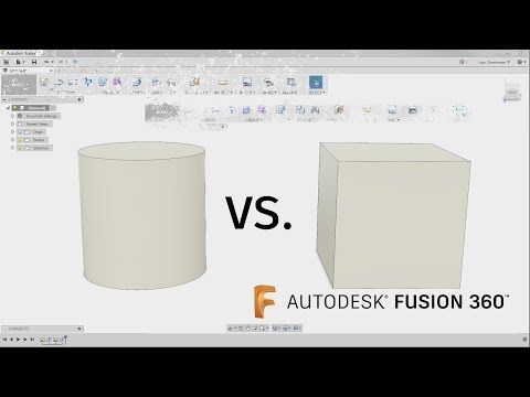
The second part of the setup, "what to print" - is indicated in paragraph Model and there you can select the entire model, component (or several)
Important fact #2 - if you are printing a multi-part model, you need to make sure that each part is in its own component.If this is not done, then fusion will work with the entire group as with one part and you will not be able to lay out individual parts on the table.Positioning tools - Move, Arrange, Automatic Orientation and Place part on platform work only with 9 components0017And finally, the third part of the setup, "with what settings to print" - this is called Print Settings and in organization this thing is very similar to Machine:
- they also need to be done in advance, before creating the setup
- they are also stored in the library
- you can also take them from the default ones, copy them to yourself and fix them
- you can also create as many as you need and then just select from the library
All print settings are stored in print settings:
9000 9000
- temperatures
- speeds
- or not (and which ones) - BRAM, SKIRT, RAFT, support
- Perimeters settings, filling
- and so on, and so on
Important fact #3 - PRINT settings can be changed directly inside the setup, these changes only affect the current setup.For example, you have an ABS profile with temperatures/speeds, but in this model you want the speeds to be different - you can easily change the settings after creating the setup and do not spoil the profile stored in the library
In total, when you put all three parts together and created a setup, you get this element
After that, you shamelessly use all the available tools for positioning parts, among which there is a wonderful Automatic Orientation, which I will talk about someday later
You change the print settings for this setup as you like without fear of damaging the saved profiles
And most importantly, you must do two things.
First, generate an extruder path ( toolpath ) for a given setup (i.e. machine + model + settings) process (3) trajectory is ready
Naturally, this procedure must be done every time you change something in the settings or setup. The rule is very simple, we see an exclamation mark - it means we need to regenerate the trajectory.

And the second important thing - you check the resulting trajectory in the built-in simulator. P-time:
Two:
Remarkable fact #4 - you can create as many setups for your model as you like. This may be necessary, for example, if you print different parts with different settings, I do this when some need to be printed with supports, and some without. We simply create a new setup, select only those components in it that should fall into it and set our own settings in the setupWhen you visually got what you need, only one step separates you from the G-code - post-processing .
The point is that the toolpath you see is not code yet. These are geometric lines, displaying the movement of the extruder, but not the code. The code is generated by a postprocessor, which is essentially a JavaScript program (but you don't need to understand these subtleties at all).
So, post-processing. When the toolpath is ready and you are satisfied, do this
Then like this:
Then like this
And that's it.
Press Post, show where to put the file, save. The code is ready.
In a nutshell, what we just did:
- select the library of pre-installed post processors
- select the default "Generic FFF Machine" post from it
- upload the code through this post processor
This whole process can be made easier, faster, better, etc. - you can make your own postprocessor and put it in your own library; you can specify in the Machine settings which post to use for your printer and where exactly to put the files with the code. And so on.
There are a lot of opportunities to flexibly bend the process to your liking.
After creating all the setups and settings, don't forget to save, because there is
Cool Fact #5 - fusion printing makes it very easy to iterate. After creating the setups and checking the settings, we can switch to Design mode and edit the model. After returning to Manufacture, we just need to click Generate toolpath to get new toolpaths for the modified model.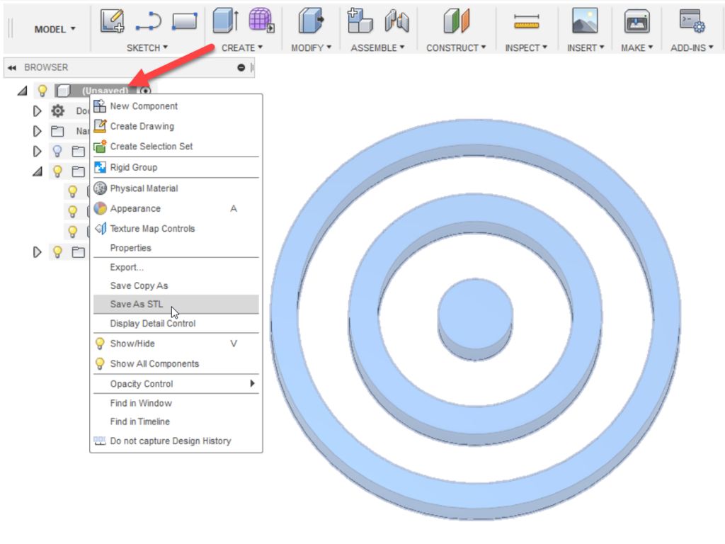
In order to discuss all this, I will organize a stream, where I will additionally present a custom post-processor, in which it is possible to use a second extruder to print the model and flexibly set the percentage of airflow 😊
That's all for now. Write in the comments what is not clear, come to the stream, ask questions.
A perfectly printed product in a few simple steps with Autodesk Netfabb
The article discusses the features of the Autodesk Netfabb software, and how to use it to prepare a product for printing in a few steps.
What's new in Autodesk Netfabb :
- Changes have been made to print simulation and analysis, with a cloud solver and unlimited print functionality in Premium versions.
- The functionality of the Premium version has been improved - Lattice commander has been added to work with cellular and lattice structures, access to cloud computing.

- The interface has changed - new buttons and commands have appeared, it has become more convenient to use the program.
- Improvement of the software core - the product has become faster and more reliable.
- Added new machines for integration.
There are 5 steps to go from creating to printing a part:
- Design - create a 3D model in Netfabb or import from another program.
- Optimization - converting a CAD model into a part optimized specifically for additive manufacturing, it will be as light as possible, acquire a certain structure that can be printed on a 3D printer.
- Preparation - dividing a part into several elements, creating a system of supports and fasteners, slicing, etc.
- Analysis - before the model is printed, a virtual simulation is carried out, which, without risks for production, will show all the dangerous areas and flaws of the designed part.

- Processing of the manufactured product on CNC machines.
Let's take a closer look at each step from creation to printing.
1. Model Design
Autodesk Netfabb Ultimate includes Autodesk Fusion 360 cloud-based CAD, the easiest solution to simplify model creation. Fusion 360 is not only CAD, but also an environment for engineering, frequency, kinematics and strength analysis.
More often, designers import ready-made models created in other CAD systems. One of the advantages of Netfabb is that the program works with a variety of file formats:
- SolidWorks;
- Catia;
- NX;
- ProE;
- 3DS;
- Alias;
- Rhino;
- neutral formats;
- direct printer formats.
Optimization The program creates cellular structures in different ways: it can fill a user-selected volume inside the model with a lattice structure, generate structures that repeat the shape of the model and fill sections of specified surfaces.

Lattice structures can consist of several surface elements.
Different types of structures can be combined and optimized for specific strengths.
The Autodesk Netfabb Optimization Utility also allows you to:
- create variable padding structure wrappers
- perform strength analysis;
- optimize the properties of parts: weight, strength, manufacturability, etc.;
- change the properties of materials: porosity, elasticity, flexibility, rigidity, etc.
Below is an example of a part weight optimization.
1 - the initial monolithic model
2 is set - the system of shells and grilles
3 is created - the load is calculated
4 - according to the results of the calculations, the structure of the part
3. Preparation for the printing
Clound a number of mechanisms and tools in Autodesk Netfabb will help the user to turn the created 3D model into an ideal part.

Part location
The program will independently determine the convenient and optimal location of the part in the printer's workspace. Edit Ranking is a command that sets the parameters for determining the position of a part. The command call is shown in the screenshot below.
After executing the command, the program will offer several options for the location of the part, they are presented in the workspace on the left in the form of a table. The table compares the specified criteria, which are colored in different colors depending on the values (red - does not meet the criteria, green - meets, yellow - boundary value).
Supports
Autodesk Netfabb generates supports automatically. In most cases, no changes are required, but for special cases, the user receives all the necessary tools for manual editing.
Automatic Wrapping
Sometimes you need to print multiple parts in one pass.
Autodesk Netfabb automatically nests parts in the printer space as tightly as possible without harming the print.
Different printers use different packing algorithms. 2D packaging places parts in a single layer on a platform, while metal or plastic powder printing uses 3D packaging. Packing is fast and error-free, the parts do not touch and do not interlock with each other, they are located at the required distance from the walls of the printer's working space.
Machine Library
It is very important for the program to work with the maximum number of printers on the market, and Autodesk Netfabb is constantly striving for this.
Trajectory fine-tuning utility
A special Autodesk Netfabb utility that allows you to fine-tune the printer control program at a fine and low level: setting hatching patterns, controlling laser or beam parameters, using laser parameters within a single construction.

4. Analysis
Before a part can be printed, it must be analyzed. Preliminary analysis allows you to identify possible inaccuracies and errors, correct them and significantly save time and financial resources.
Netfabb Simulation is a tool that allows you to produce and calculate:
- print simulation;
- prediction of possible problems;
- visualization of strains and stresses;
- deformation compensation;
- protect the printer from damage.
5. Processing
After printing, parts often require additional processing on CNC machines - for this, a special PowerShape utility is built into Autodesk Netfabb, which allows you to:
- work with faceted geometries as with surface;
- set allowances for subsequent CNC processing;
- to fill holes that are not printed immediately, but are drilled by hand;
- add holes;
- build temporary structures for error-free printing.

Learn more