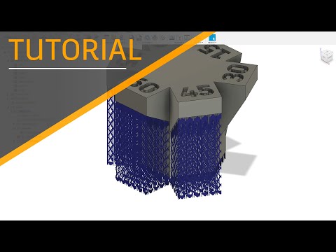
Finishing 3d print
Ultimate Guide to Finishing 3D Printed Parts
Time to read: 13 min
The purpose of this article is to detail the different finishing methods for FDM and PolyJet 3D printed parts and the techniques/tips that can elevate the look and feel of your prototypes.
A simple Apple Watch stand design will be utilized as a case study. This stand is a model with pockets and internal and external features that needs to be surface finished to a standard that complements the shiny exterior of an Apple Watch put on it.
Here’s a quick overview of the main points this article covers:
- PLA: If you’re working with a tight budget then PLA is going to be your best material choice; the results aren’t as polished but the price is cheapest.
- ABS: If your budget is moderate then go with ABS. It’s not as cheap as PLA but still at a low price point and the material is more reliable than PLA.
- VeroBlack or VeroWhite: For the highest quality parts go with VeroBlack/VeroWhite.
This will give you the best dimensional accuracy and best overall polished look.
The 3d printing post-processing needed for the watch stand parts involves a combination of repairing and preparing the print for post-processing, sanding, and painting.
The finished sample 3D printed parts with all three materials should be smooth, matte black surfaces. Inherent to the 3D printing process, with every print are unique challenges and considerations to arrive at the best finish possible. Although there are ways to mitigate the challenges, experience in 3D printing goes a long way.
The print settings process for each material is detailed separately and a summation of the results may be found in the conclusion of this article.
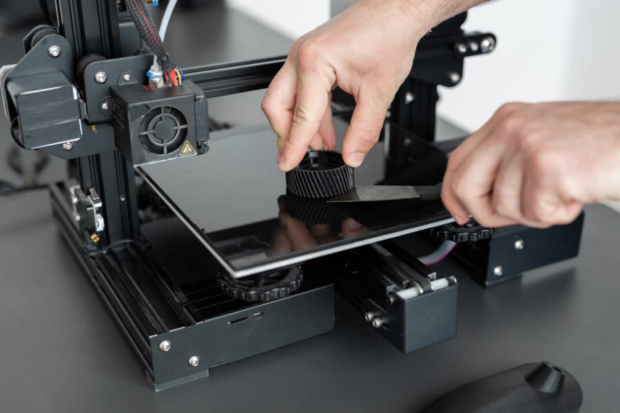
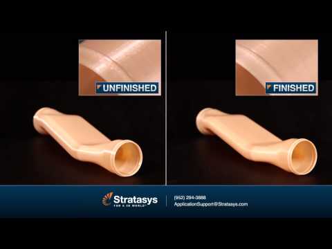
ABS (Printed on a Dimension Elite)
The Dimension Elite prints are smooth, clean, and ready to sand out of the NaOH bath.
There are, however, clear stepping lines between the printed layers. If we don’t remove these stepping lines, they’ll show up in the final paint coat which will ruin our smooth finish. Thankfully, removing these will be easy thanks to ABS’s high melting point and easy sandability.
Materials Needed
The materials we’ll be using:
- Sandpaper (grits 100 to 600)
- Medium, fine, and extra-fine sanding sponges
- XTC-3D brush-on coating (As an alternative, Bondo putty is a common solution to fill holes in parts. We chose XTC-3D for its viscosity, sandability, and ability to penetrate small perforations, which makes it desirable over Bondo putty)
- Razor blade
- Foam brush, mixing cups and popsicle sticks
- Sandable Krylon Primer
- Montana Acrylic Primer in Shock Black
- Matte Acrylic Varnish
Sanding
Sanding the ABS print is simple and straightforward. First start with 100 – 200 grit sandpaper to remove stepping lines and then gradually increase up to 600 grit to achieve a smooth finish without sanding lines.
Pro Tip: Sand in small circular movements evenly across the surface of the part. Avoid sanding in one direction only, especially in the direction of the stepping lines to prevent striations or “trenches” in the print.
Beware that ABS is very easy to sand, so be careful not to overdo it. Removing as little as .010” can be enough to completely remove any stepping layers and oversanding can compromise critical dimensions.
After sanding the parts, some holes are revealed on our part left by an incomplete layer around the letters DIM. These holes can perforate through the finished paint coat to create ugly sinkholes, so we need to find a solution.
As you can see in the Catalyst tray to the right, there are large holes between the DIM and the edge of the part. Moving the DIM up in our Solidworks model would solve this, but for now we’ll have to find a way to fill these holes with a sandable filler.
Repairing the Incomplete LayerWe’re going to use a thin, sandable epoxy called XTC-3D to fill the tiny holes and crevices in our print. XTC-3D is cheap (a 24 oz bottle costs about $25), quick, thin, and effective. Note that a small amount goes a long way (within the 10 minute pot life).
Pro Tip: Be sure to maintain a weight ratio of 100 Part A to 42 Part B. Mix thoroughly for one minute and coat your part within the 10 minute pot life. For more details, check Smooth-On’s technical bulletin here, and a great instructional example here.
Before applying the XTC-3D, wash the part with soap and dry with compressed air to ensure your part is thoroughly clean and free of any oils or sanding dust. Also make sure to wear gloves so as not to get any hand oils or sweat on your part.
Fill in holes or gaps in your print with a very thin (1/64”) coat; a thin layer of XTC-3D will level itself out. We used a razor blade to scrape excess XTC-3D into the unwanted holes and gaps, making sure to avoid any areas we didn’t want filled (like the letters DIM).
Allow the XTC-3D sufficient time to become tack-free dry (approximately 2 hours). Now we’re ready to continue sanding away at the excess XTC-3D layer with 300 to 600 grit to reveal the repaired surface.
Then, after another thorough wash, we’re ready to begin preparing our repaired surfaces for painting.
Priming and Painting
Painting 3D printed parts is a vast world of acrylics, enamels, sprays, and airbrushes.
In this example, we’ll be using Montana spray can paints to follow a relatively straight forward process: prime, dry, paint, dry, varnish, dry.
Standard spray painting principles apply:
- First make sure your surface is oil-free, dust-free and hole-free
- Shake your cans for at least two minutes prior to painting
- Ensure your cap is clean to prevent drips
- Be aware of how the paint is accumulating on the part and look for any pooling or dripping
- Paint in many light coats rather than fewer heavy coats; this is especially important for 3D printed parts with internal and obscured geometries
- Paint in controlled, well-ventilated and well-lit areas
The Dimension prints started with very obvious stepping between layers. If you’ve sanded properly up until now to create as smooth a surface as possible, these layers shouldn’t show up in your final paint finish.
The finished ABS part is matte black and smooth to the touch with very little evidence of layering in most surfaces. A few important results to note here:
- Sharp internal pockets are tough to sand. After about 30 minutes of sanding, we still had a hard time removing all the layering and the stepping shows up even after priming, painting, and varnishing the print.
- Because we had to remove more surfaces from the sanding, there is some sacrifice in regards to the final geometry of the part.
- Filling the incomplete layer with a thin coat of XTC-3D worked very well; those holes are invisible in the final paint layer.
VeroBlack (Printed on an Objet30)
Thanks to .0011” resolution, the Objet30 prints have some stepping between layers, but nowhere near as obvious as in our FDM prints.
The Objet30 prints come out of the printer with a thick layer of support structure material so before we can begin finishing our VeroBlack part, we’ll need to remove this support structure and the residue it leaves behind.
VeroBlack 3D Printed Part Materials NeededThe materials needed for post-3D printing finishing:
- Sandpaper (grits 100 to 600)
- Medium, fine, and Extra fine Sanding Sponges
- Sandable Krylon Primer
- Montana Acrylic Primer in Shock Black
- Matte Acrylic Varnish
Start with 100 grit sandpaper to wet sand the residue and gradually move to wet sand with 300 grit sandpaper; the residue will fall off in small soft white chunks. This is the hardest part of the VeroBlack finishing process and it took us about 30 to 40 minutes to remove all the residual layer.
After removing the residual layer by wet sanding utilizing 300 grit sandpaper, the surface of the part will begin to feel smooth. If you rub the part with your fingernail, you’ll feel it’s harder and more plastic-like beneath the gummy residual coat. Continue wet sanding through to 600 fine grit sandpaper until the part is fully smooth.
Pro Tip: Water breaks up the residue, so wet sanding is a highly effective method to get a smooth, residue-free, paintable, and homogenous surface.
Thoroughly clean your part with soap and water before you move on to the next step to remove any additional residue. Again, we recommend using compressed air to dry the part and clear any accumulated dust.
Beware that VeroBlack is like ABS: very easy to sand, so be careful not to overdo it. Once you break through the residual layer, the actual VeroBlack will sand very easily. Removing as little as .005” can be enough to completely remove any stepping layers. Be careful as oversanding can compromise critical dimensions.
VeroBlack 3D Printed Part Priming and PaintingNext, we’re going to paint the VeroBlack part just as we did the ABS part: using Montana spray can paint with the following process: prime, dry, paint, dry, varnish, dry.
Standard spray-painting principles apply:
- First make sure you have a good surface quality which is oil-free, dust-free and hole-free
- Shake each paint can for at least two minutes prior to painting
- Ensure your cap is clean to prevent drips
- Be aware of how the paint is accumulating on the part and look for any pooling or dripping
- Paint in many light coats rather than fewer heavy coats; this is especially important for 3D printed parts with internal and obscured geometries
- Only paint in controlled, well-ventilated, and well-lit areas
The finished VeroBlack part is matte black and smooth to the touch. A couple points to note here:
- Some of the internal corners were not sanded enough to remove the residue, so you can see how the paint powdered up in these areas.
 This will likely result in peeling paint over time.
 - Although very little stepping is visible on the part, you can see slight evidence of it here. This part could have probably used 30 more minutes of thorough sanding.
Now for the dreaded PLA, a notoriously difficult material to finish. But with some tricks and patience, it too can join ABS and VeroBlack in the ranks of matte black glory!
This Replicator print came off the plate with severe striations: see the parallel grooves in the layers of the part above. This could be a result of machine quality, but for now we’ll just have to find a way to maneuver these striations to a smooth part.
Sanding PLA is difficult, in part because of how soft and gummy it becomes if you try to sand too aggressively or quickly, so we’ll explore options on how to smooth 3d prints with minimal effort and abrasion.
PLA 3D Printed Part SandingIf you choose to sand the PLA directly, the process is straightforward. Note: PLA acetone smoothing is not advisable. PLA smoothing is not as forgiving as ABS when it comes to sanding and abrasion, so you will likely spend more time removing the stepping between layers, especially with the severe striations in a print like ours.
Begin with a low (100 – 200) grit sandpaper, sanding away at the bumpy striations and any raft or support material (aluminum foil) left behind. Particularly in the case of MakerBot support, it’s easiest to remove them with a flush cutter or pair of pliers and brush them with a rotary multi-tool first before sanding away at them.
Depending on the size and geometry of your part, you’ll likely be stuck in the 100 – 300 grit sandpaper range for a while to smooth out striations and pesky support structure remnants.
Once layering and striations are less prevalent, move through finer grits (400 – 600) sandpaper to achieve a shiny surface ready for priming and painting.
Pro Tip: Patience is key when sanding PLA. Turn on a movie or your favorite show, but don’t zone out! Sand in small circles evenly across the surface of the part. If you’re using a sanding multi tool on PLA, be careful not to overheat/melt your 3D printed part.
An alternative method to sanding PLA prints directly is smoothing the PLA print with the XTC-3D first and then sand on top of the coating.
PLA 3D Printed Part FinishingWe’re going to use XTC-3D to create a smooth, sandable, paintable layer of epoxy clear coat glossy finish around our PLA print.
Before applying XTC-3D, ensure that your part is thoroughly clean, free of any oils and sanding dust (sensing a pattern yet?). Wash the part with soap and dry with compressed air to clear any dust. Again make sure to wear gloves to protect both your part and your hands.
Brush on the XTC-3D in a thin (1/64”) coat; as long as the coat is thin enough, it will level itself out. Between coats, leave 1.5 hours for the XTC-3D to dry.
It may be difficult to coat an entire part at once, so don’t be afraid to do it in sections, making sure to keep overlapping to a minimum between sections. Wait 90 minutes between first and second coats and after you’ve finished wait 2 hours to allow the shiny surface to become tack-free.
With striations as severe as ours, it will take multiple coats to get a smooth uniform surface, so patience is key. Remember that multiple thin glossy finish coats will level better than thick coats.
Pro Tip: Internal pockets are susceptible to pooling so be careful to suck up or remove any pooling that occurs before the XTC-3D begins to dry (that’s what we’re doing in the left picture above).
Beware that XTC-3D may compromise critical dimensions, but applying thin glossy finish coats will allow you to minimize the additional material.
After the XTC-3D layer has hardened (two hours after application of the last coat) it should be ready for sanding. Follow basic sanding guidelines, starting with 300 grit sandpaper (thanks to the smoothness of the XTC-3D) and sanding in small circular movements to even the surface. Any wavy patterns may require a coarser grit sandpaper to remove.
The sandpaper will scratch up the XTC-3D coat; focus on getting a level surface, moving through to 600 grit sandpaper.
After you’ve finished sanding 3D prints, make sure to thoroughly clean your part with soap and water and then dry using compressed air before moving on to the next step.
PLA 3D Printed Part Priming and PaintingPainting PLA parts follows the same process as the ABS and VeroBlack parts: prime, dry, paint, dry, varnish, dry.
Standard spray painting principles apply:
- Make sure your surface is oil-free, dust-free and hole-free
- Shake your cans for at least two minutes prior to painting
- Ensure your cap is clean to prevent drips
- Be aware of how the paint is accumulating on the part and look for any pooling or dripping
- Paint in many light coats rather than fewer heavy coats; this is especially important for 3D printed parts with internal and obscured geometries
- Paint in controlled, well-ventilated and well-lit areas
The XTC-3D coated PLA part is matte, black, and has a smooth surface to the touch with a few problems:
- Although the XTC-3D has worked well to smooth the part and make sanding quicker and easier, it has left pooling in the internal pocket that has shown through the paint finish.
- Striations are still visible on the part. 30 more minutes of sanding 3D prints could have prevented these from showing through the final paint finish.
After finishing all three parts to a smooth, matte black finish, let’s take a look at the differences in process, time, materials and finish.
Differences in ProcessABS (Dimension Elite)- Sand from 100 to 600 grit
- Repair holes with XTC-3D (may not apply to your part)
- Sand away XTC-3D with 300 to 600 grit
- Prime, Paint, Varnish
- Sand from 100 to 600 grit
- Prime, Paint, Varnish
- Coat in 1 to 3 layers of XTC-3D (depending on how bad the striations on your print are)
- Sand away XTC-3D with 100 to 600 grit
- Prime, Paint, Varnish
The part that took the longest to finish was PLA due to the XTC-3D coating time. Even without XTC-3D, however, PLA typically takes longer to sand than ABS or VeroBlack.
In our example, the VeroBlack was ultimately faster to finish since we repaired our ABS print with XTC-3D and stepping between layers was not as significant in the VeroBlack print.
All things considered, VeroBlack was the quickest to get to a smooth, matte black finish.
Pro Tip: If you’re in a rush to get from printer to photoshoot, pick the Dimension Elite or Objet30. Especially in models with overhangs and significant amounts of support material, the Dimension Elite and Objet30 both have support material that is quickly removable via dissolution, whereas the PLA support on a Replicator can significantly increase the time required to get to a smooth surface part.
Differences in Cost and MaterialsIt’s important to consider the amount of time it will take to finish your model as well as the overall look and dimension when considering the price.
PLA is the cheapest out of the three, at $20 per part, followed by ABS at $55, and VeroBlack at $110. In our opinion, VeroBlack is the best bang for your buck since it’s the shortest to surface finish and will give you the most accurate model.
At first glance, all three models may look very similar, but there are a few key differences in the final finish.
Both the ABS and the PLA finished prints have evidence of stepping between layers that is visible in the final paint coat. The VeroBlack print requires much less effort to remove these steps, which ultimately are not as obvious in the final paint coat.
Although the ABS and the VeroBlack finished prints have very similar surface finishes, more material (approximately .020”) was lost in the sanding process for the ABS to remove stepping between layers. In contrast, the VeroBlack print required less sanding, so the final object dimensions are closer to the original design intent.
Individual Summary of Each PartVeroBlack: High layer resolution (. 0011”) means little sanding is required to get a smooth, paintable part. Critical dimensions don’t need to be compromised to get a smooth surface quality part and no repairs are needed for fine detailed features.
ABS: Parts are easy to sand, but small fine detailed features may require repairing and careful sanding to remove stepping between layers. Once this stepping is removed, painting is straightforward.
PLA: The cheapest option, but also has the potential to be the most difficult to finish, depending on support structures and quality of the print. May require significant sanding and repairing via XTC-3D or Bondo filler.
Browse our website to learn more about our capabilities, such as 3D Printing and CNC Machining.
Quick Facts:
- Finishing a 3D printed part often involves a combination of the following processes: smoother application, sanding, polishing, cleaning and painting. The process is unique to the material type.
- A smooth finish with 3D printing is achievable but, post-processing will greatly improve the smoothness of parts.
- Epoxy resins are an excellent choice for sealing PLA printed parts.
- Acetone smoothing is not recommended for PLA prints.
- In general, IPA or rubbing alcohol will not dissolve PLA but there are some varieties that may be IPA soluble. Consult your filament material datasheet or technical datasheet for more information.
- PLA may be smoothed without sanding by dipping it or spraying it with a coating.
- ABS is tougher and lighter than PLA which is stronger and stiffer. Both have their ideal applications, but PLA is typically considered a hobby material whereas ABS is ideal for prototyping.
How to Finish Your 3D Prints - Ultimate Guide to Filling, Priming, Sanding & Painting 3D Printed Parts
Your 3D prints are now coming out great & looking as they should, but then again, they’re still looking like they’re 3D printed.
Whether you’re printing for business, want to rescue a not-quite-perfect print, or just need some tips for finishing 3D printed parts, this guide on how to finish 3D prints will explain the various methods the experts use: allowing you to learn the full lowdown on how to smooth out 3D prints.
In general, finishing is the post-printing process of smoothing the surface of a printed object so that it looks as perfect and professional as possible. Large industrial 3D printers accomplish this task by using acetone cloud chambers, multi-axis enamel jets, and agitating chemical baths.
However, I’m guessing you don’t have to have that kind of expensive equipment to finish 3D printed parts that are smooth and sharp.
In this article, we’re going to look at the various finishing techniques that you can use to get perfect-looking printed objects every time. Because every print material requires slightly different finishing techniques, we’re going to look at each of the common finishing techniques in turn and see how they apply to a material you may be using.
This will give you an opportunity to decide what may work for you given your individual setup, circumstances and printing practices.
Basic Best Beginning Practices for 3D Print Finishing
On the subject of printing practices, one of the best ways to minimize the amount of finishing work cleaning up 3D prints is by starting at the very beginning of the printing process. Your slicer settings have a lot to do with how your finished object looks.
For example, layer height contributes greatly to how a finished object looks. Layer height is the setting that establishes the height of each layer of filament in your print. In some sense, layer height in 3D printing is akin to resolution in photography or videography.
When you choose a thicker layer height, your object will have less fine detail and the layers will be more viable. When you choose a thinner layer height, a higher level of detail is possible and your layers will tend to blend into one another.
Print speed is another important setting that can contribute to overall object quality. Print speed is how fast the print head travels while extruding filament. Therefore, optimal speed depends on the object you are printing and the filament material that you are using to fabricate the object.
In general, simple objects with less detail can be printed faster without much loss of quality. On the other hand, more complex objects with more detail will benefit from a slower print speed. Because of this, it pays to experiment with your print speed to see what works best for the job you’re printing.
If you’re intending on painting 3D printed parts after you’ve finished printing, it may be best to use a lower layer height. You’ll spend more time printing, but less time sanding 3D printed parts before painting them. Read on to learn more about painting PLA and other 3D materials.
You’re going to be sanding 3D prints after printing in order to obtain the smoothest surface possible. This means that your object is going to need to be a bit more robust in terms of thickness and infill than you previously planned for.
A shell is the outer wall of a designed object. Shell thickness refers to the number of layers that the outer wall will have before infill printing will begin. The higher the setting is for shell thickness, the thicker the outer walls of your object will be.
Obviously, thicker walls make for a sturdier object. So, when you’re planning to finish your object post-printing through sanding, you want to increase the shell thickness to account for the material that you will be removing later.
Fill density or infill is a measure of how much material will be printed inside the outer shell of the object in question. Fill density is usually measured as a percentage of whole, as opposed to a unit of measure. This means that if 100% fill density is selected, the printed object will be solid, with no empty space inside the outer shell. Likewise, if 0% is selected, the printed object will be empty inside.
Fill density is used to conserve filament while printing and speed up printing times. However, an object with more infill will be stronger and heavier than an object with less infill. Again, because sanding removes material from the surface of an object and requires the application of a certain amount of pressure to do so, you’re going to want to increase your fill density when printing the object. Doing so will insure that your object won’t be damaged or deform during the finishing process.
For more information on slicer settings, take a look at our article on the subject here.
Slicer settings are not the only thing that affects the amount of potential finishing work that may need to be done once an object is printed. The quality of the printing filament that you are using can impact end quality as well. Poor quality filament contains impurities that will negatively affect how the material melts, extrudes and cools.
In addition, cheaper filament is not produced to the rigid tolerances necessary for high-quality end results. Specifically, variations in the diameter of the filament can lead to under extrusion and over extrusion problems during printing, both of which will produce a final object with serious surface flaws that will have to be dealt with through finishing.
Finally, consider using a color of filament that will closely match the desired color of the finished object. Doing so will reduce the amount of painting that needs to be done once printing is over and you’re finishing the object.
Admittedly colour is less important for those truly professional-grade finishes though, because of the amount of primer paint coats needed.
Support Structures
As you know, a 3D printer starts printing an object from the bottom up. This means that if you have a design that incorporates overhangs, upper areas in your model that don’t have any underlying material, you’re going to run into problems. After all, your printer filament is subject to the law of gravity. It can’t be extruded onto thin air.
In these cases, you will have used a support structure which supplies a surface onto which your overhangs could be printed. These structures, which may or may not be soluble, will need to be removed before the finishing process can begin.
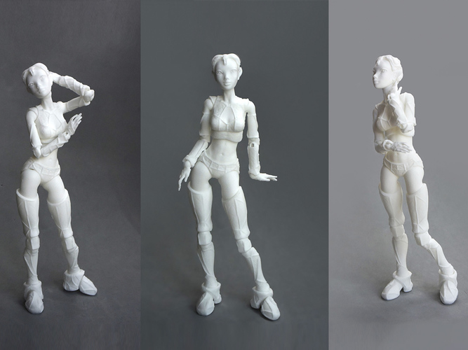
If your support structure isn’t soluble, you will need to break or cut away the supporting material. A pair of flush cutters or an Exacto knife can help you get cuts that are flush with the printed surface of the object that you wish to retain. Once the supporting material has been removed, use a bit of 200 grit or 400 grit sandpaper to gently smooth the support marks.
You’ll notice in the image above, the model was printed upside down so that minimal support structures would be left – and so less work to remove them. It’s also easier going smoothing PLA on large, simple areas like the top of the helmet than potentially more intricate parts of the underneath.
If your support structure is soluble, you’re likely dealing with either PVA or HIPS. In this case, simply submerge the object in the solvent in question – water for PVA and Limonene for HIPS. The water should completely dissolve the PVA support structure within several hours.
Limonene will take longer to dissolve the HIPS support structure, usually about 24 hours. In both cases, remember to give the containers containing the solvent and your object a gentle shake from time to time to help the process along.
How to Clean Up 3D Prints With Filler
Before you sand and paint 3D printed models, it may be worth filling any small gaps, cracks, or underfilled sections with a 3D print filler solution. This is usually a variant of epoxy resin that is easy to work with, and can be sanded down afterward.
We recommend using XTC-3D which you can get here. You’ll notice you can even use it for smoothing out 3D prints just by brushing it over as a 3D print coating.
Although you won’t get the same level of high-quality finish we’re aiming for in this article – it could be a quick way to improve a print. Think of it as the lazy man’s 3D printing finishing tip.
The neater you are filling the gaps, the less sanding you’ll need to do afterward – so try to be as neat as possible.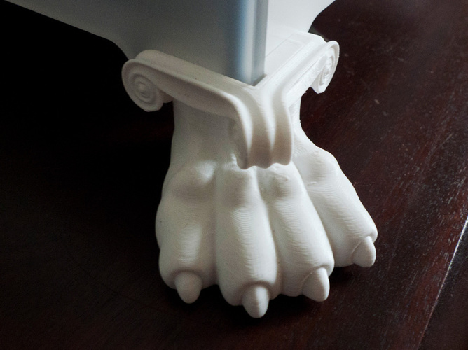 You’ll also need to leave it to cure for at least a few hours after filling.
Sanding is a simple and somewhat easy way to finish processing a 3D print, depending on the material in question. Some printing materials respond well to sanding, with other materials it may not be an option.
For example, PLA and ABS can respond very well to sanding. With harder materials, like Polycarbonate and PMMA, sanding is not an option. (We will discuss finishing options for harder materials in more detail below.)
If you’re looking for how to make 3D prints smooth and the material you’re using can’t be vapor smoothed, then sanding it is!
Among the few PLA finishing techniques, sanding gives the best result. Be sure to choose a good quality PLA filament, as poorer filaments can be more challenging to get a good smooth surface on.
Sanding the surface of an object made from PLA or ABS is a fairly straightforward process – as long as you approach the job with some patience. For example, PLA’s lower melting temperature can make it get gummy and soft if it is sanded to aggressively and quickly. Therefore, patience and a bit of time are the keys to getting a smooth mirror finish on any object made with PLA.
Also, you need to be prepared to use multiple grit sizes of sandpaper. For example, with PLA be prepared to use every size from a 200 rough grit to a 3000 fine grit and every gradient in between.
Pro tip: With a material that’s a bit harder, like ABS, you may want to start with the same grit size but try wet sanding the object with a waterproof abrasive sheets such as “Wet & Dry.” A harder material can stand increased pressure while being sanded, but friction still is an issue.
Wet sanding helps reduce the heat that results from friction, allowing for more efficient removal of unwanted material with less deforming of the object due to frictional heat.
No matter the material, you want to start with the coarsest grit of sandpaper. Use a circular motion with a slow moderate pressure to remove unwanted material. The idea is to get rid of what you don’t want while leaving absolutely no trace that you’ve done any finishing work.
Once you’ve gone over the object once with coarse grit sandpaper, you want to repeat the process with a finer grit. For example, if you started with a 200 grit sandpaper, you want to switch to a 400 grit sandpaper on your next pass. Once you’ve patiently done a pass over the object with the 400 grit, you switch to 600 grit and repeat the process.
The idea is to slowly and carefully remove the features on the objects that you don’t want, while slowly and carefully retaining and highlighting the finish on the features that you do want to keep.
When you are scaling up the grit number on the sandpaper, remember that time is your friend when it comes to getting a mirror-smooth finish. In general, the more time that you spend sanding, the better the finish that you will obtain. This is especially true with the lower-numbered grit sandpapers.
Keep working your way up to finer and finer sandpaper grits – 600 to 800, 800 to 1000, and so on. As you get up over 1000 grit, the finish on your object will start to feel really smooth, but don’t stop here. To get a truly professional finish, take the time to carefully go over your object with 2000 girt and then 3000 grit. That extra attention will really pay off in the quality of the finish that you end up with.
Once you’ve sanded your object, it’s ready for either painting or simply polishing, depending on your preference. For more detail on this 3D sanding technique, view our guide on getting a mirror finish from sanding here.
Vapor Polishing
The before and after effects of a cold acetone smoothing bath.An alternative to sanding is vapor polishing. With vapor polishing, a small amount of an applicable solvent is placed in a container. The printed object is also placed in the container on a platform that suspends it above the solvent. A non-airtight cover is placed on the container and the solvent is then heated until it begins to produce vapor.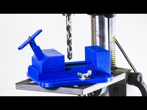
This is an analogous process to what happens when water is heated to a point where it begins to form steam. Essentially, the solvent in question is brought to a temperature where it steams, or begins to transition from a liquid to a gas.
Once this happens, the solvent “steam” is allowed to surround, coat, and interact with the surface of the printed object. Ideally, the gaseous solvent begins to slowly and evenly dissolve the surface of the object, removing unwanted material and features.
Once the desired look of the surface of the object is achieved, the object is removed from the container and allowed to air dry. Drying stops the interaction of the solvent with the material the object is made of. The end result is an object with a smooth and professional finish.
As was the case with sanding, increasing shell thickness and fill density prior to printing will produce a more robust object that will be capable of withstanding vapor polishing without problems.
Vapor polishing softens the rough surface layers of the object so that they flow together to produce the desired finish.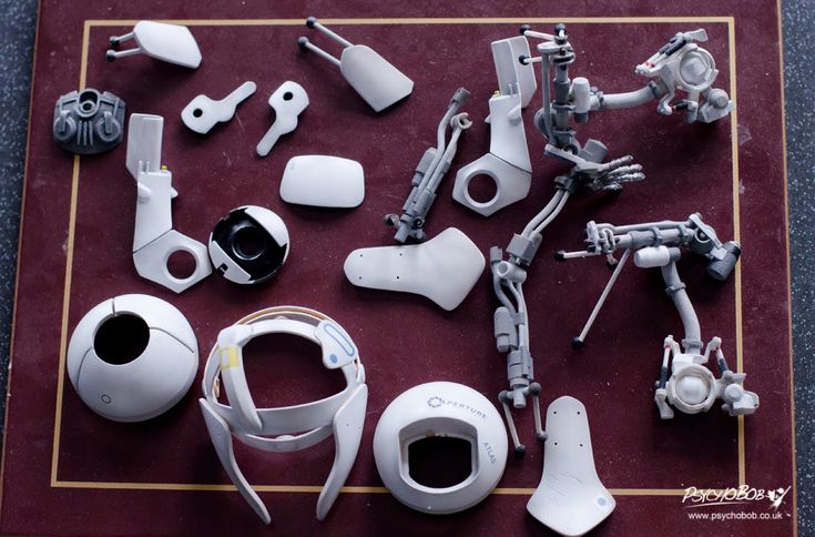 So if there are insufficient top layers present when using this process, just like with sanding, the undersurface of the object can be exposed and ruin the effect.
While industrial printers and finishers use cloud chambers to vapor polish projects, many makers replicate the process using common objects. For example, a wide-mouthed glass container with a lid or a simple saucepan can be used to hold the solvent. A raft or platform of aluminum foil can be used to suspend the object above the solvent. Finally, the heated bed of your printer or your home range can be used to carefully heat the solvent.
Now a word of caution. Every printing material is soluble is a different substance. Some of these substances are relatively benign, others are extremely toxic.
For example, in ascending order of toxicity, PVA is water-soluble. HIPS is soluble in Limonene. ABS and PMMA are soluble in acetone. PLA is most efficiently soluble in tetrahydrofuran or THF. Polycarbonate is soluble in dichloromethane. The list goes on.
Vaporizing any chemical solvent poses a number of hazards. First, solvent steam is much more readily absorbed by the body through respiration and contact. The more toxic the solvent, the worse the prolonged exposure to the substance will be. Therefore, any vapor polishing must be done in a well-ventilated environment. The use of a respirator, protective clothing and gloves is well neigh mandatory.
Second, many solvents are flammable. Therefore, heating a solvent must be done under controlled conditions. You need to know the solvent’s boiling point and flame point beforehand and use a calibrated thermometer to ensure the temperature of the solvent stays within safe parameters. Always work with a fire extinguisher handy. To read more about vapor polishing, check out our in-depth guide here.
How to Paint 3D Printed ObjectsNo matter if you’re prototyping an object for use in a Kickstarter campaign or simply want to create something that’s absolutely stunning in its presentation and perfection, painting may be the way to go.:quality(90)/images.vogel.de/vogelonline/bdb/1157300/1157362/original.jpg)
Successful finishing using paint actually involves two separate processes – priming and then painting. However, before looking at either, let’s take a look at a preliminary step that you need to take that will guarantee stellar results once you start painting.
If you’re wondering: can you paint 3D printed objects – the answers yes of course, but you need to do the right…
Preliminary Steps
When priming and painting an object, it’s best to first mount it on what’s known as a painting block using a dowel. A painting block is nothing more than a block of wood that supports the object while it is being primed and painted.How to paint PLA: Here you can see the helmet raised up, ready for finishing touches.
Simply take a wood dowel and, using a drill with a bit that is equivalent to the dowel’s diameter, drill a small hole into an inconspicuous area of your object. Insert the dowel into the hole you’ve drilled until it sets securely. (Alternatively, you can use a naturally occurring hole or declivity in your object to seat the dowel. )
)
Next, using the same size drill bit, drill a hole into a block of wood large enough to securely balance and support your object. Insert the other end of the wood dowel that you used on your object into the wood block. You now have a way to provide even and smooth coats of primer and paint to your object without having to touch it and risk leaving smears and fingerprints behind.
Also, remember that priming and painting an object can be a messy business. You want to stop the paint from getting on objects that it shouldn’t and you want to keep foreign objects, like dust, from settling on your printed object while it dries. Therefore, work in a well-ventilated area that is clean and well-lit.
Most spray-on paints contain solvents that can aerosolize and be inhaled. Consider wearing an approved respirator and nitrile gloves while priming and painting.
Also consider constructing a simple spray booth by hanging plastic sheeting around three sides of the surface you will be placing the object on while priming and painting.
This will contain the paint to the area around the object and will reduce the amount of dust and debris that will adhere to the object while the paint or primer is drying.
Priming before painting 3D printsPrimer for 3D prints is a special type of paint that comes in neutral colors. It is designed to provide a uniform surface that paint can easily bond to. Primer comes in both brush-on and spray-on varieties. When choosing a primer for your object, you are better off going with a spray-on variety.
It will cover the surface of your object with an even coat and will eliminate the use of brushes which can leave noticeable brush marks.
Best paint for 3D prints? For best results, use a primer (and paint) that are compatible with plastic and are of the same brand. Using a high-build filler primer like Krylon and Montana both are good choices.
Before priming your object, spend at least two to three minutes swirling the contents of the can of primer, using a circular motion.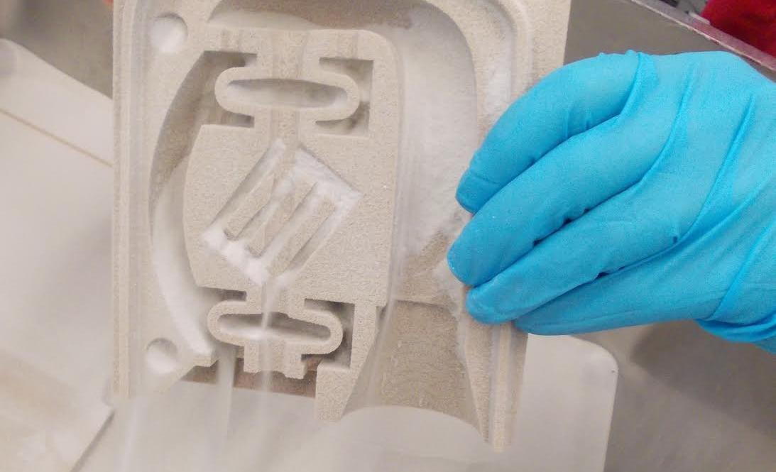 Doing so fully dissolves the pigment into the solvent within the can. You should never, under any circumstances, shake the can before you prime or paint. If you do, you will mix the pigment into the solvent, instead of dissolving it.
This will result in the formation of bubbles that will appear on the surface of your object while spraying. After about two or three minutes of swirling, you should hear the metal ball within the can moving smoothly. This indicates that the pigment is dissolved into the solvent and you are ready to begin priming your object.
Start with the nozzle of the can about 15 to 20 cm (6 to 8 in.) from the surface of the object. Using short and rapid strokes, begin spraying the object Start each stroke before the beginning of the object and end each stroke after the end of the object. Move quickly, rotating the object as needs. Avoid over-spraying. The goal is to start with a very thin initial coat that can be built up over time.
Once the initial coat of primer is dry, it’s time to add a second coat.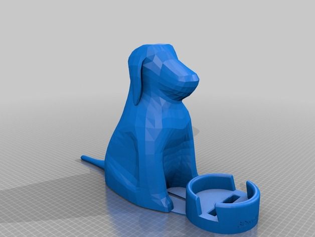 Again, use short rapid strokes that start before the beginning of the object and end after the end. In the vast majority of cases, your object will only need two coats of primer to ensure an even cover that will improve the adherence of the paint you have chosen.
Once your second coat of primer is dry, you want to buff and polish the primer coat. A great and easy way to do this is to use nail buffing sticks, the kind that are available in any chemist or drug store and are used in manicures and pedicures. They come with a three grit surface.
You can skip the roughest surface and use the buffing and polishing surfaces to bring the primer coat up to glossy shine. As you did with the sandpaper, take your time and use a circular motion where possible. The goal is uniformity. When you’ve finished, gently wipe the object with a tack cloth to remove any dust created during the buffing and polishing.
Once you’ve buffed and polished the primer coat, you’re ready to begin painting. The painting process itself involves three distinct steps – undercoating, top coating and clear coating. As was the case with the primer coat, your best bet when painting is to use a spray-on variety. It will give you greater control over uniformity and layer thickness. It will also allow you to avoid brush marks.
You want to choose a painting that goes on as thinly as possible. One of the best choices is Tamiya. Tamiya paints are specifically designed for use by modelers and radio control enthusiasts. This makes them a perfect choice for finishing painting 3D printed objects.
Undercoating
Applying an undercoat layer will allow you to get the richest and deepest color when painting your object. An undercoat should not be confused with the primer coating. The two serve entirely different purposes. The primer coat is there to give the paint something even to adhere to. It prevents blotching and uneven coverage.
The undercoat layer is there to block the neutral and flat color of the primer. Undercoat layers are usually either solid black or white. Black is used for objects that will be a painted with darker toned colors. Obversely, white is used for objects that will be painted with lighter-toned colors. No matter the color, the undercoat will shine through the topcoat layers, giving the finish a luster and depth that is unmatched.
As was the case with the application of the primer, you want to use a respirator and gloves while painting. Spend two or three minutes swirling the paint can in a circular motion until the pigment dissolves in the solvent. You’ll know that this happened when you feel the metal ball in the can revolve around the inside without resistance.
Once the paint is well mixed, hold the nozzle of the can 15 to 20 cm from the surface of the object and apply the undercoat in short and rapid strokes. Once again, start these strokes before the beginning of the object and end after the end of the object. As always, rotate the object on the painting block while applying the undercoat in the thinnest layer possible.
Once the initial undercoat layer is dry, buff and polish the undercoat layer using a nail buffing stick in the same manner as you did when buffing and polishing the primer. Once this is completed, you are ready to apply a second undercoat in the same manner as the first. Once the second undercoat is dry, buff and polish as you did before.
Top Coating
Now it’s time to apply the top coat. Top coating isn’t about complete coverage. In some sense, it’s the icing on the cake. It’s there to enhance and improve all the work that you’ve already performed. Ideally, the top coat will be a color that contrasts with the color of your undercoat. The top coat will add gradients of color which will allow the contrast of the undercoat to show through. The end result will be a depth and resonance that will make your object look amazing.
All of the steps that you’ve already used when applying the primer coat and the undercoat are also used when applying the top coat. You want to use a respirator and gloves. You want to keep your object mounted on the paint block. You want to keep and the nozzle of the paint can 15 to 20 cm from the surface of the object and use short rapid strokes while painting. You want to rotate your object rapidly on the paint block while applying the top coat. You want to polish and buff in between the first and second coats.
You want to make sure that you don’t apply the paint too thickly when doing the top coating. Remember, the goal is to let some of the contrast of the undercoat to show through the top coat in order to get a sense of depth. To that end, check that there is sufficient contrast showing after the first top coat layer has dried and been polished and buffed. Depending on what you find, apply the second top coat accordingly.
Clear Coating
Clear coating, also known as finish coating, is the last step in the painting process. The purpose of clear coating is twofold. First, the clear coat adds final layers which enhance the finished look of the object. Second, the clear coat protects all of the hard finishing work you’ve already done under a protective coating.
There are two types of clear coating available – glossy and matte. Obviously, glossy is shinier and matte provides a flatter-looking end appearance. The choice between the two is merely aesthetic. Practically, they both do the same thing.
Clear coat is applied in the same way that you’ve applied every other coating. Respirator, gloves, well-swirled coating, short rapid strokes, etc. You can apply either one or two coats of clear coating depending on the circumstances and the finished look that you’re trying to achieve.
I hope this guide has been a comprehensive breakdown of the available options to you for 3D printing post-processing and gives you a clear layout on how to paint 3D printed models. If you’re willing to put in a little time, truly exceptional finishes can be achieved. But if you’re just looking for tips on smoothing out 3D prints, then this guide will at least have given you some food for thought.
Related:
- How to sand PLA to a smooth finish
- Best infill settings
- How to prevent filament stringing and pillowing
G-CODE in Russian for 3D printing (Mini-guide)
Often, for high-quality printing, and especially when selecting print parameters, it is necessary to be able to read and edit the G-code during calibration.
A commonplace example: setting your own values for the "Temperature Tower" or creating start and end blocks of codes in slicers for a specific printer.
On some sites (like reprap.org/wiki/G-code) on the Russian-language pages, the commands are only partially described in Russian, and the rest in English. On some domestic sites, the commands are translated into Russian, but some are given with errors - stupidly copy-paste a clumsy translation.
Tired of searching through different sites, trying to find the CORRECT description of a particular command and its parameters.
I made myself such a mini-reference book. I'll be glad if anyone else finds it useful.
I tried to describe the maximum number of commands used, except for very specific ones.
(Yes, special commands for deltas, for example, sorry, I consider them specific and not necessary for me)
However, most commands are supported by all printers and firmware.
Attention! Compliance of commands and parameters is checked only for Marlin firmware.
G-commands
G0(G1) Xnnn Ynnn Znnn Ennn Fnnn – movement.
G0 - fast idle
G1 - linear working travel
Xnnn, Ynnn, Znnn – coordinates.
Еnnn - amount of extruded material in mm (with negative values - retract).
Fnnn – travel speed in mm/min (this speed will be used until the next change).
G0 X12 (will move 12mm in X)
G0 F1500 (Set travel speed to 1500 mm/min.)
G1 X90.6 Y13.8 E22.4 (Move 90.6mm in X and 13.8mm in Y while extruding 22.4mm of material. )
)
G4 .
Pnnn - Timeout, in milliseconds
Snnn - Timeout in seconds.
"G4 S2" and "G4 P2000" - equivalent to
G10 - Plastic rollback (Retract)
Filament rollback according to M207 settings.
G11 - Plastic feed
Feed / reposition the head according to M208 settings.
G20 - Inch unit setting
G21 - Setting the units in millimeters
From now on, the reading will be in inches/millimeters.
G28 - Move to start ("home") until limit switches actuate
G28 – home on all axes.
G28 X Z - Move home only in X and Z axes
G29 - Create table curvature mesh (MESH_BED_LEVELING)
The command allows you to create a compensation (Z-height) grid and use it later when printing. The grid can be used repeatedly even after the printer is turned off.
After using the G28 command, the mesh created by the G29 command flies off.
It is necessary to save the rhinestone mesh after it has been created! To recall the grid from memory, use the M420 command.
Be sure to use G28 before using G29, otherwise the mesh will be incorrect.
Creating Mesh Bed Leveling manually (via commands):
1. Enter G29 S0 to start meshing.
2. Enter G29 S1 to set the first grid point.
3. Align the nozzle with paper (as usual).
4. Enter G29 S2 to save the value and jump to a new point
5. Repeat steps 3 and 4 until the creation procedure is completed.
6. Enter M500 to write the resulting mesh to EEPROM.
Creating Mesh Bed Leveling using the printer menu (the function must be active in the firmware):
1. Select Prepare followed by Auto home (aka G28 command).
2. Select Prepare and then Level Bed.
3. Wait for on-screen instructions to begin. Press the "twist" on the screen when the inscription "Click to Begin" appears. The head will go to the first grid point.
4. Use the thumbwheel to raise or lower the nozzle to align the nozzle with the paper. Same as when leveling the table. After you have achieved the desired gap between the nozzle and the piece of paper, press the "twist". The head will move to a new grid point.
5. Repeat step 4 until the program has passed all points.
6. When finished, enter the Control menu and select the Store memory item to save the created mesh to EEPROM.
To use the grid stored in EEPROM when printing, use the command
M420 S1 (See M420).
G90 - Setting absolute coordinates
All coordinates are absolute relative to the machine origin.
G91 - Set relative coordinates
All coordinates from now on become relative to the last position. Marlin translates all axes into relative coordinates, including the extruder.
G92 Xnnn Ynnn Znnn Ennn - Set position
This command can be used without any additional parameters.
G92 - reset all axis coordinates to zero.
Xnnn - new X coordinate
Ynnn - new Y coordinate
Znnn - new Z coordinate
Ennn - new extruder position
Example: G92 X10 E90
M-commands
M17 - Enable/Enable all stepper motors
M18 - Remove current from motors
Motors can be turned by hand. Command analog M84
M20 - List of files on SD card
M21 - SD card initialization
If the SD card is loaded when the printer is turned on, this will happen by default. The SD card must be initialized for other SD card functions to work.
M22 - Release SD card
The specified SD card will be released. On future (random) read attempts, a guaranteed error occurs. Useful before removing the SD card.
M23 - Select file on SD card
Example: M23 filename.gco
M24 - Start/continue printing from SD card
The printer will print from the file selected with the M23 command.
M25 - SD card print pause
M28 - Start writing to SD card
Example: M28 filename.gco.
A file is created on the SD card, designated as filename.gco (if the file exists, it is overwritten) and all subsequent commands to the printer are written to this file.
M29 - Stop writing to SD card
Example: M29 filename.gco
The file opened by the M28 command is closed and all subsequent commands are executed by the printer in normal mode.
M30 - Delete file from SD card
Example: M30 filename.gco. filename.gco will be deleted.
M32 - Select file and start printing from SD card
Example: M32 filename. gco.
gco.
Used for SD card printing and works the same as M23 and M24
M80 - Enable ATX Power Supply
Puts the ATX power supply into sleep mode. Does not work on electronics without sleep mode.
M81 - Turn off the ATX power supply
M82 - Set the extruder to absolute mode
M83 - Set extruder to relative mode
Allows extruder to be extruder in absolute/relative units
M84 SNNN X, Y, Z, E - transfer motors to the waiting mode of
SNNN - time per seconds.
If a timeout is specified with Snnn, this command simply sets the stepper motor inactivity timeout.
If no motors (X,Y,Z or E) are specified, this command immediately disables all.
If one or more axes are specified, this command disables the specified ones immediately. For example, "M84 S10" will put stepper motors into standby mode after 10 seconds of inactivity.
M92 Xnnn Ynnn Znnn Ennn - Set the number of steps per axis per unit
Ennn - steps per unit for extruder
Examples: M92 X87.489 Y87.489 Z87.489 or M92 E420
Allows you to set the number of steps per unit (usually mm) for motors. These values are replaced with the values from the firmware at power up unless written to the EEPROM see M500.
M104 Snnn - Set extruder temperature and DO NOT wait
Snnn - Set temperature
Example: M104 S190
Sets the temperature of the active extruder 190C and immediately returns control (that is, DOES NOT WAIT for the extruder to reach the set temperature). See also M109
M105 - Get Extruder Temperature
Gets the temperature of the active extruder and hot bed in degrees Celsius. The temperature is transmitted to the connected computer. The response sent to the computer might look like this: ok T:201 B:117
M106 Snnn - Turn on the fan blowing part
SNNN - fan rotation of the fan from 0 to 255 (127 - 50% speed)
m107 - turn off the fan
m108 - cancel the heating 9000 9000 temperature set by M109 and M190, continues printing.
M109 Snnn - Set extruder temperature and wait
Sets the temperature in Celsius and waits for it to be reached. See also M104
M110 Nnnn - Set current line number
Nnnn - Line number
Example: M110 N123
In this example, the number of the current line 123 is set. Thus, it is expected that the next line after this command will be 124.
M112 - Emergency Stop
m114 - receipt of current positions 9
M115 - Get a firmware version
m119 - get the status of ends
m140 - set the temperature of the table and DO NOT wait
Example: M140 S65
Sets the table temperature to 65C and immediately returns control (ie DOES NOT WAIT for the table to reach the set temperature). See also M190
M190 - Set table temperature and wait
Sets the temperature in Celsius and WAITS to reach it.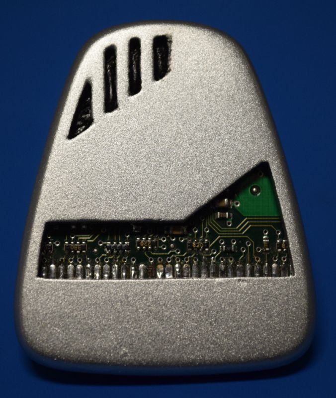 see M140
M200 Dnnn Tnnn - Set the REAL diameter of the filament rod.
Dnnn – diameter in mm.
Tnnn – extruder number. (can be omitted for single extruder printers)
Example: M200 D1.65
Used to calculate the actual extruded volume.
See M404 for rating setting.
M201 Xnnn Ynnn Znnn Ennn - Setting of the maximum accelerations (in mm/s in sq.)
for axes.
Ennn - accelerations in mm/s in sq. for the extruder.
Only one/two of the parameters can be used.
Example: M201 X1000 Y1000 Z100 E2000
Use M500 to store parameters in EEPROM
M202 - Setting the maximum acceleration for simple (idle) movement.
!Not used in Marlin! V mm/s in sq. Example: M202 X1000 Y1000
M203 Xnnn Ynnn Znnn Ennn - Setting the maximum speed (in mm/s)
Xnnn, Ynnn, Znnn - max speed for axes
Ennn - max extruder speed.
Only one/two of the parameters can be used.
Example: M203 X6000 Y6000 Z300 E10000
Use M500 to store parameters in EEPROM.
M204 Pnnn Rnnn Tnnn - Acceleration setting (in mm/sec. in sq.)
Pnnn - Printing acceleration
Rnnn – Retract Acceleration
Tnnn - Accelerations during idle movements
Only one/two of the parameters can be used.
Example: M204 P800 T3000 R9000
Use M500 to store parameters in EEPROM.
M205 Xnnn, Znnn, Ennn - Setting the maximum jerk (jerk) (mm / s)
Xnnn - jerk along the X and Y axes. (Jerks are the same along these axes)
Znnn - jerk along the Z axis.
Ennn - extruder jerk.
Only one/two of the parameters can be used.
Example: M205 X30 Z5 - Set jerk X/Y = 30, Z jerk = 5.
Use M500 to store parameters in EEPROM.
М206 Xnnn, Ynnn, Znnn - Set offsets relative to limit switches (zero)
Similar to G92 command, but these offsets can be written to EEPROM see M500.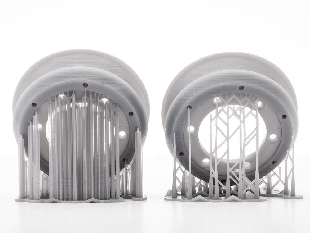
Example: M206 X10.0 Y10.0 Z-0.4
M207 Snnn Fnnn Znnn - Set retract parameters (bar retraction)
Snnn - positive retract value in mm.
Fnnn – feedrate mm/sec.
Znnn - lift (lift) of the head along the Z axis in mm during retract. (Helps avoid hitting the model)
Example: M207 S4.0 F2400 Z0.075
Used subsequently for G10 and G11 commands.
Use M500 to store parameters in EEPROM.
M208 Snnn Fnnn – Bar feed recovery parameters after retract
Snnn – positive feed value in mm.
Fnnn – feedrate mm/sec.
Use M500 to store parameters in EEPROM.
M209 Snnn – On/off automatic retraction
Snnn – value 1 – on, 0 – off
Used if the slicer does not support the G10 and G11 commands.
Each extrusion command will be classified as a retract, depending on the value (positive or negative).
M218 Tnnn Xnnn Ynnn – head offset setting
Tnnn - head number
Xnnn, Ynnn – X,Y coordinates.
Example: M218 T0 X50 Y10.5
M301 Hnnn Pnnn Innn Dnnn — Write hotend PID parameters(!)
Hnnn – extruder number. h2 - the first exruder (hotend).
Pnnn - Proportional gain (Kp)
Innn - Integral factor (Ki)
Dnnn - Derivative coefficient (Kd)
Example: M301 h2 P1 I2 D3
Use M500 to store parameters in EEPROM.
See M304 for writing table PID.
M302 Snnn - Allow extrusion at Snnn and above.
Snnn - Set temperature
Example: M302 S170 – enable extrusion (turn on the extruder motor) at a nozzle temperature of 170C and above. M302 S0 - extrude at any temperature.
M303 Ennn Snnn Cnnn - Start PID calibration process for table/hotend
Ennn - E0 hotend, E1 table.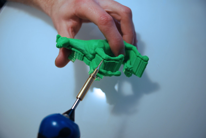
Snnn is the calibration temperature.
Cnnn – number of calibration cycles. More cycles - more precise parameters.
Example M303 E1 C8 S110 – table PID calibration at 110C for 8 cycles.
The PID parameters will be displayed as a string on the terminal screen of a program running in connection with the printer, such as Repetier-Host.
M304 Pnnn Innn Dnnn - Write table PID parameters(!)
Pnnn - Coefficient proportional (Kp)
Innn - Integral factor (Ki)
Dnnn - Derivative coefficient (Kd)
Example: M301 h2 P1 I2 D3
M301 - without parameters will display the current parameters.
Use M500 to store parameters in EEPROM.
For writing extruder PID see M301.
М404 Wnnn - Setting the nominal filament thickness 1.75 or 3.
Wnnn - nominal (theoretical) filament thickness in mm.
Example: M404 W1.75
M404 - without parameters, will display the current nominal value as a string.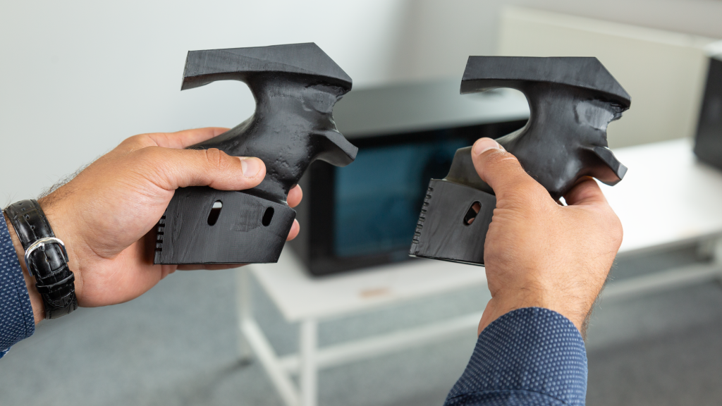
This value is used to determine the percentage difference in the automatic rate adjustment in response to the measured filament width and must match the value used for the filament width in slicer settings.
Set actual filament thickness, see M200.
М420 Snnn – Enable/disable the use of the table curvature compensation grid (MESH_BED_LEVELING)
Snnn – S1 on, S0 off.
M420 S1 – use the table curvature compensation grid loaded from EEPROM when printing.
See G29 to get the current status and create a table curvature compensation grid.
M500 - Save data to EEPROM
M501 - Reading data from EEPROM
M600 - Command for automatic filament change
Simplification of work with a 3D printer using GCode macros
Content
-
- G-CODE structure
- GCode commands
- G-command
- M-Komandrdi
- m-Khomanda printers
- Initial
- Between Layers
- End
- Special
- Cura Macros
- Basic Command Tables
If you look in the dictionary of computer terminology, then a macro (or macro command) is a software algorithm of actions recorded by the user.
 That is, by definition, the computer must repeat the actions of a person. But in 3D printing, the term has a different meaning. Instead of recording and repeating human actions, the 3D printer will also execute commands, but now they will be written by hand, and not using a slicer. This allows you to directly control the actions of the printer, bypassing the standard way of slicing the model with a slicer. If you look at the GCODE file with notepad or any other text editor, you will see thousands and even tens of thousands of lines with a combination of letters and numbers. It may be scary, but in fact, almost any macro can be written in 5-10 lines. The main thing is to understand the order of writing a separate command.
 Structure of G-code files
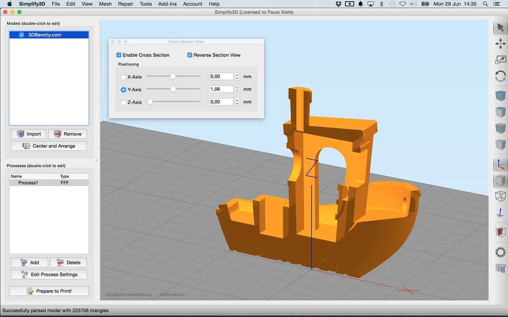
Each GCODE file can be divided into 2 parts: the comment that occurs at the beginning of the program and after the commands, and the commands themselves. Consider the example of a model sliced using PrusaSlicer (Version 2.
 3.0).
3.0). In the first line we are greeted by the name of the slicer, its version, date and time of slicing:
; generated by PrusaSlicer 2.3.0+win64 on 2021-04-22 at 12:31:50 UTC
Please note that at the very beginning of the line there is a semicolon sign, it indicates a comment. Everything that is in the line before it is read by the printer, but it does not pay attention to what is after it.
Next, we see several lines that show us the line width settings that the slicer used to slice the model. All of them are comments.
; external perimeters extrusion width = 0.45mm
; perimeters extrusion width = 0.45mm
; infill extrusion width = 0.45mm
; solid infill extrusion width = 0.45mm
; top infill extrusion width = 0.40mm
; first layer extrusion width = 0.40mm
After that there are lines that describe the initial temperatures, the command for finding the zero point of coordinates and the commands for moving.
 All commands that are involved in the beginning and the process of printing will be discussed further.
 Tip: Many slicers, when slicing the GCODE for the printer, leave comments in the file indicating the layer change and / or its number. This will help in orienting in commands during manual editing.
Gcode command
Many are mistaken, calling this language for the operation of a 3D printer a programming language. In fact, this is a generally accepted format for working with CNC machines, including 3D printers. Each command is on a separate line and represents the name of the command (letter and number) and its parameters (also letters and numbers). For example, a command to move the nozzle to a certain coordinate with plastic extrusion:
G1 X101.912 Y136.607 E2.04825
G1 - team name
X101.912 - X coordinate
Y136.607 - Y coordinate
E2.04825 - amount of extruded plastic
All commands are divided into two main types:
-
G commands
-
M commands
There are other few types, but they are not used in 3D printers, so we will omit them in this article.
G commands
All commands in this group are for movement or calibration. A 3D printer does not use all of them, and not every 3D printer uses the same commands as another. For example, there is a command to auto-calibrate the table. Obviously, if this function is not provided for in your printer by design, then this command will not be executed. Below is a table of the most popular G-commands:
Team Options Description G0 X - X coordinates
Y - Y coordinates
Z - Z coordinatesMoving without plastic extrusion G1 X - X coordinates
Y - Y coordinates
Z - Z coordinates
E - amount of pressed plastic (mm)Moving with plastic extrusion G4
S - time in seconds
P - time in millisecondsPause G28
X-axis X
Y - Y axis
Z - Z axisMoving to zero coordinates.
If parameters are specified, then parking only along the specified axes
G29
The parameters differ depending on the firmware. Automatic construction of a table height map G90
- Transition to absolute coordinate system (all coordinates are relative to zero) G91
- Change to relative coordinate system (all coordinates are relative to the current position of the nozzle) G92
X - X coordinates
Y - Y coordinates
Z - Z coordinates
E0 - coordinates of extruder No. 0 (amount of extruded plastic)Set position without movement and extrusion
M commands
These commands are auxiliary. They are mainly related to setting and calibrating temperatures, working with files, and setting up movement parameters.
Team Options Description M17
X - motors according to X
Y - Y motors
Z - motors according to Z
E0 - extruder motor No. 0Supply power to all motors if no parameters are specified. Otherwise, only the specified M18 X - motors according to X
Y - Y motors
Z - motors on Z
E0 - extruder motor No. 0Power off on motors
Command reverse M17
M20
- Listing files from an SD card M21
- Memory card initialization M22
- Disabling the memory card M23
After the command enter the name of the file Selecting a file from the SD card M24
- Start execution of file selected with M37 M25
- Pausing SD Card Printing M28
After the command enter the name of the file
A file with the specified name is created or overwritten, all commands that are entered into the printer via a wired connection will be written to it
M29
After the command enter the name of the file
The file with the specified name is saved.
 All further commands are executed as usual.
 M30
After the command enter the name of the file
Deleting a file with the specified name
M82
-
Switching to absolute mode for the extruder
M83 - Switching to relative mode for the extruder
M92
X - value on X
Y - Y motors
Z - motors according to Z
E0 - extruder motor No. 0Set the number of steps per millimeter for each specified motor
M104
S - nozzle temperature Set the nozzle temperature without waiting for heating up to the set temperature
M105
-
Print nozzle temperature to console
M106
S - rotation speed (from 0 to 255)
Turn on fan with speed indication
M107
-
Turn off the fan
M108
-
Cancel waiting for the nozzle to heat up to the temperature specified in M109 and M190
M109
S - nozzle temperature
Set the nozzle temperature and wait for heating to the set temperature
M112
-
Emergency stop:
All heaters turn off
Motors are de-energizedM119
Xn (1/0) - X axis limit switch
1 - invert value
0 - do not invert valueGet the status of the limit switches on the axes, if parameters are not specified
M140
S - table temperature
Set the table temperature without waiting for heating to the set temperature
M190
S - table temperature
Set the temperature of the table and wait for heating to the set temperature
M200
D - diameter (in millimeters)
T - extruder numberSet filament diameter
M201 X - acceleration for the X axis
Y - acceleration for the Y axis
Z - acceleration for the Z axis
E - extruder accelerationSetting accelerations along the axes
M205
X - jerk for X axis
Y - jerk for Y axis
Z - jerk for the Z axis
E - extruder jerkSetting the jerk along the axes
M206
X - offset along the X axis
Y - offset along the Y axis
Z - offset along the Z axisSetting the offset relative to the limit switches
M300
S - frequency in Hertz
P - duration in milliseconds
Emits a beep at a specified frequency for a specified time
M301
H - heater number
P - coefficient P
I - factor I
D - coefficient DSet the value of PID parameters for a given heater
Some of the above commands can be used before printing to evaluate the status of the printer, such as M20 and M119.
 But many other commands are used to create macros, which we will describe next.
 Macro types for 3D printers
Like any other text document, GCODE files can be edited in Notepad. But for this you need to open the file every time, find the desired section and enter your macros. Instead, many slicers offer to manually enter macros, which will then be automatically inserted at the beginning, end or middle of the GCODE file. PrusaSlicer has the most flexibility - you can add a macro in it at the beginning, at the end, before and after layer changes, during a pause and between objects in a sequential print. Next, we will look at the most popular and convenient macros.
Initial
All macros of this type are designed to prepare the printer before printing. For example, with a single M301 command, you can set the PID on the printer for different temperatures. This can be very important, as the PID depends not only on the characteristics of the printer and its design, but also on the temperature of the print.
 If the hot end is very inert, then the PID values for different temperatures will differ slightly, so it makes no sense to change them every time. But if the hot end has low inertia, then the difference in PID coefficients for different temperatures is large enough to spoil the model due to temperature jumps. You can read more about PID tuning in the article on choosing the print temperature on our website. Once you find the value of the PID parameters for the temperatures you print most often, they can be substituted into the initial GCode. In PrusaSlicer, this can be done in the "Printer Setup" window, inside the "Custom Gcode" tab.
 For convenience, you can create several printer profiles for different temperatures at once.
Loading filament
If you change the plastic every time you print, then for convenience you can use a small macro to change / refill the filament before printing:
G91; setting the origin relative to the last position
G1 E-100 F2400; Pulling out the filament
G4 S15; Pause for 15 secondsG1 E100 F2400; Filament loading
G90; Transition to absolute coordinates
G92E0; Setting the extruder coordinate to zero
The value of the E parameter in the two G1 commands must be matched to your printer.
 If you have a bowden extruder, then measure the length of the tube in millimeters and add 30-50 millimeters, then insert the resulting value into parameter E. If you have a direct extruder, you can insert a value of 50-70mm. Paste all the received code into the “Starting G-code” window after the standard commands.
Attention: after each change, do not forget to save the profile!
Between coats
This group contains macros that directly affect the printing process. They are often the most difficult, due to the need to manually edit the GCode file in notepad or other text editor. But in fact, there is nothing complicated about this, because each such file has comments that make it easy to find the desired section of code. For example, you can add a sound signal when changing layers. To do this, use the M300 command:
- M300 S500 P800
It should be borne in mind that the simplest speaker is installed in the printer, so you should not specify a frequency below 500 Hz, as the sound will be quieter and greatly distorted.
 You can use this site to select the frequency. The square waveform most closely resembles the sound of a speaker. Once you have chosen the appropriate frequency and time, the resulting string can be pasted into the “G-code executed on layer change” window.
 Filament change
This macro allows you to print one model in several colors on a printer that has one extruder. There are only 2 limitations: the color will change exactly at the border between the layers, and with each layer change, you need to manually change the filament.
First you need to determine the place to change the layer. To do this, calculate the height at which the boundary between the layers is located. This is easy to do with the formula:
Layer change height = layer number * layer height (in millimeters).
After you find the height, you need to open the Gcode file and find the first line in it, which contains the Z parameter with the desired layer height. For example, we need to change the color of the calibration cube on the tenth layer, while we print with a layer height of 0.
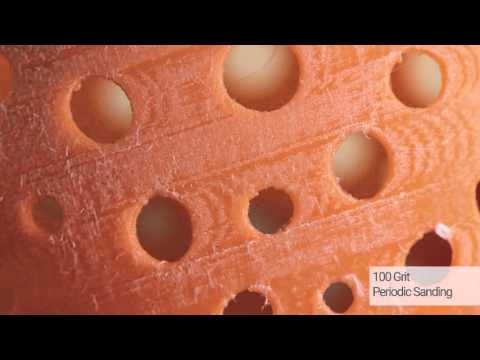 2 mm. So in the Gcode file you need to find the first line where there is Z5. Then, after the comments that the slicer put, you need to insert the following macro:
 G91; transition to relative coordinate system
G1Z5; raising the nozzle by 5 mm
G90; change to absolute coordinate system
G1 Y10 X10 F1000; moving to the edge of the table
G4 S60; pause 60 seconds (at this time you need to insert the plastic)
G91; transition to relative coordinate system
G1 E100 F100; filling plastic
G92E0; zeroing extruder coordinates
G90; change to absolute coordinate system
In the end, your file should look something like the image below:
If you translate these commands into human language: as soon as the next layer begins, the printer raises the nozzle and moves it to the edge of the table. It then waits 60 seconds for you to replace the plastic. After that, the printer will extrude 100mm of loaded plastic to stabilize the flow and continue printing.
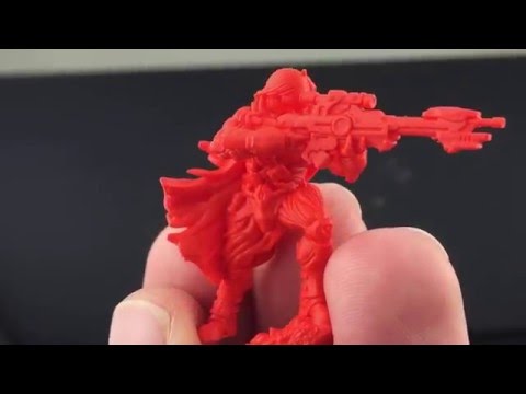 This command can be inserted several times, but keep in mind: each layer change adds 1-2 minutes to the total print time and requires your active actions.
 End
All slicers at the end of printing leave standard commands: raising the nozzle, turning off the heaters and blowing. But if several models are printed one after another, then it will take a lot of time to reheat the nozzle and table. To prevent the printer from turning off the heat, you must remove the M104 S0 command from the “Final G-code” window. You can also increase the convenience of working with a 3D printer by adding a macro to play a sound signal at the end of printing.
Sound notification
To play the end-of-print melody, you must add one or more M300 commands after the standard commands in the End G-code window. For example, you can insert three consecutive beeps:
M300 S1000 P100
M300 S1000 P100
M300 S1000 P100
Or the opening theme from Mario:
M300 S2637 P150
M300 S2637 P150
M300 S0 P75
M300 S2637 P300
M300 S2093 P150
M300 S2637 P300
M300 S3135 P300
M300 S0 P300
M300 S1567 P300
Star Wars:
M300 S1396 P166
M300 S1396 P166
M300 S1396 P166
M300 S932 P1000
M300 S2793 P1000
M300 S2489 P166
M300 S2349 P166
M300 S2093 P166
M300 S1864 P1000
The Simpsons:
M300 S2093 P562
M300 S2637 P375
M300 S2959 P375
M300 S1760 P187
M300 S3135 P562
M300 S2637 P375
M300 S2093 P375
M300 S880 P187
M300 S1479 P187
M300 S1479 P187
M300 S1479 P187
M300 S1567 P750
And even music from Indiana Jones:
M300 S1318 P240
M300 S0 P120
M300 S1396 P120
M300 S1567 P120
M300 S0 P120
M300 S2093 P960
M300 S0 P180
M300 S1174 P240
M300 S0 P120
M300 S1318 P120
M300 S1396 P960
M300 S0 P360
M300 S1567 P240
M300 S0 P120
The scope for imagination is huge, so you can come up with your own composition and record it in the form of M300 command sequences.

Interesting fact: the author of the Make Anything channel played a tune from the Nintendo service using a 3D printer. The highlight of this video is the use of not only the speaker on the printer board, but also the sound of motors and even a kind of maracas printed on the same printer.
Special
This group of macros includes exceptional macros that are often inapplicable, but in some situations they can greatly simplify printing. For example, a macro for sequential printing of models. That is, the printer prints a model, then either the printer itself or a person separates the part from the table, and the printer starts printing the next model. This process has many limitations and is extremely difficult to customize specifically for your printer. An example of the execution of this idea can be seen in this video.
Nozzle cleaning
If the nozzle gets dirty quickly and you are tired of cleaning it, and you don’t have a silicone cover for the hotend, then you can clean the nozzle before each print using a metal brush.
 To do this, you need to fix a metal brush in the far corner of the table, and add the following lines to the initial G-code, after the nozzle heating commands:
 G28; Movement to the origin
G90; change to absolute coordinate system
G0Z10; raising the nozzle to “Cleaning Height”
G0 Xnnn Ynnn; moving to the far edge of the brush
G0 X(nnn-10) Ynnn; moving to the near edge of the brush
G0 Xnnn Ymmm
G0 X(nnn-10) Ynnn
G0 Xnnn Ymmm
G0 X(nnn-10) Ynnn
G0 Xnnn Ymmm
G0 X(nnn-10) Ynnn
G28; return to origin
Here, instead of Xnnn and Ynnn, there should be the coordinates at which the far edge of the brush is located. For example, for a 200x200mm table, the movement commands would look like this:
G0 X195 Y195
G0 X185 Y195
The height at which the nozzle will be located must be selected experimentally. It is desirable that the bristles of the brush completely cover the nozzle, but do not interfere with its movement.
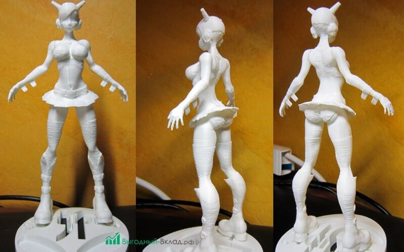
Attention: the brush must be firmly fixed, otherwise, when it is separated from the table, it can block the movement mechanics and break the motors!
Macros in Cura
Relatively recently, the Cura slicer has acquired the ability to edit Gcode in the program itself. A distinctive advantage of this method is the feedback between the slicer and this function, which allows, for example, to display the remaining print time directly on the printer screen.
To start working with macros, you need to open the post-processing window. To do this, select the “extensions” tab in the toolbar, then “post-processing” and click “Change G-code”.
A post-processing window will open in front of you. In the left half there will be a list of plugins, on the right the settings of the selected plugin. Working with multiple plugins is similar to working with layers in Photoshop. Scripts will edit the Gcode file in order, meaning a script can affect upstream scripts, but not vice versa.

The following is a list of scripts and their brief description:
-
Change at Z
This script allows you to change the speed, temperature, flow and blowing power at a certain height. The values are applied to all subsequent layers. You can also choose to display changes on the printer screen. Basically the script is used to print test models.
-
color mix
This script is for mixing extruders (eg A10M from Geeetech). Unlike just two-color printing, this extruder can mix two plastics, which allows you to create transitional shades.
-
Create Thumbnail
Create icons for Ultimaker Format Package (.ufp) files. Used when implementing a slicer in Octoprint.
The name speaks for itself: displaying the file name and layer number on the screen.
Displaying the remaining print time on the printer screen
-
Filament Change
Automate the Gcode editing process for changing filament.
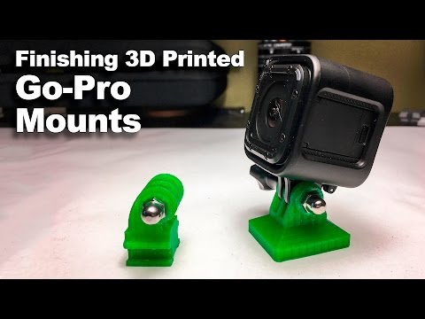
It is an analogue of the Gcode insertion windows when changing the layer in PrusaSlicer
-
Retract Continue
Allows you to add recoil during nozzle movement between parts of the model
-
Search and Replace
Removes the specified characters and replaces them. If replaced with a space character, then this script simply removes the specified characters
-
time lapse
This script helps in creating high-quality time-lapses using the camera. At each layer, the printer will move the carriage to the side and send a command that can activate the camera.
If your printer has the ability to build a table height map, then this script will replace the repeated height measurement with the result of previous measurements.
The most commonly used and useful plugins are Change At Z and Search and Replace. They cover 80% of all required changes in Gcode.
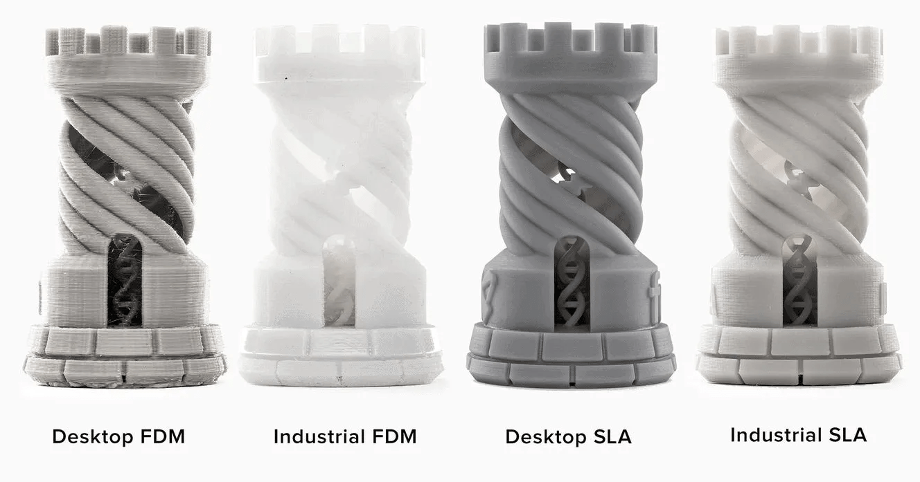 Therefore, even if you are not going to use them in the near future, it is still better to study them at least at a superficial level.
 Basic command tables
When servicing the printer, the final step in checking and setting up is to self-diagnose the printer and check it in operation. But not all actions can be done from the printer menu. For convenience, we have collected all the necessary commands in one small table that you can quickly open and use.
Team Options Description G28
X-axis X
Y - Y axis
Z - Z axisMoving to zero coordinates.
If parameters are specified, then parking only along the specified axes
M92
X - value on X
Y - Y motors
Z - motors according to Z
E0 - extruder motor No.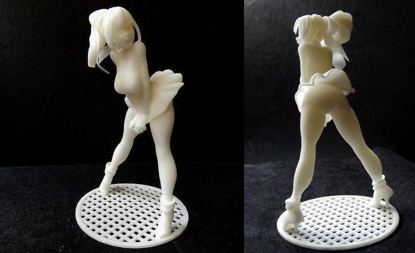 0
0 Set the number of steps per millimeter for each specified motor
M303
S - temperature
C - number of cyclesPID autotuning command. The more cycles, the higher the accuracy
M301
H - heater number
P - coefficient P
I - factor I
D - coefficient DSet the value of PID parameters for a given heater
M112
-
Emergency stop:
All heaters turn off
Motors are de-energizedATTENTION! If the printer gives an extruder or bed heating error, then the M112 command may not fix the problem, as often this error occurs when the transistors / relays are “jammed” or shorted! It is better to immediately turn off the power to the printer, and then find out the cause of the error.
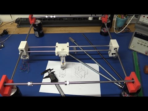
Learn more