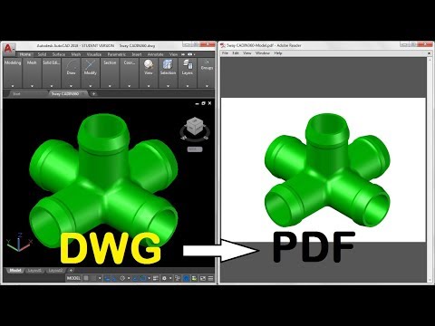
Dwg to 3d printer
How to convert CAD to STL for 3D Printing
How CAD files are exported to STL is an important process for accurate building of parts. The step by step process for converting CAD to STL was taken straight from the mentioned companies websites.
STL is the standard file type used by most or all rapid prototyping systems. A STL is a triangulated representation of a 3D CAD model, an example is shown below:
Solid test Facet normal 0 1 0 Outer loop Vertex 0 4 0 Vertex 0.517638 3.93185 0 Vertex 0.5 3.93185 -0.133975 Endloop Endfacet Endsolid test
The triangulation of a surface will cause faceting of the 3D model. The parameters used for outputting a STL will affect how much faceting occurs (figure 2 and 3).
Coarse STL File produces larger triangles, rougher finish
You cannot build the model any better or smoother than the STL file, so if the STL is coarse and faceted, that is what you can expect in the final model.
Fine STL file produces a smoother model
In the CAD package, when exporting to STL, you may see parameters for chord height, deviation, angle tolerance, or something similar. These are the parameters that affect the faceting of the STL. You don’t necessarily want to go too small. The finer the STL the larger the file is in size, which will affect processing time in Insight as well as build time. Below is some information found on the Internet regarding exporting to STL from various CAD packages.
CAD to STL Conversion
Listed below are the steps for creating an STL file from different CAD systems. The list is ordered alphabetically by product.
Note: Please consult your user’s guide or the software developers for more information or technical support. If your CAD software is not listed below, please contact your CAD software technical support for information about exporting to an STL.
3D Studio Max
- First check for errors
- An STL object must define a complete and closed surface.
 Use
Use - Select an object.
- Click Modify
- Click More …
- Select “STL-Check” under Object-Space Modifiers
- Select Check
- If there are no errors, continue to export the STL file by:
- Clicking File>Export
- Select “StereoLitho [*.STL]” in Save as type
- Select location in Save in
- Enter a name in File name
- Click Save; OK
- Export To STL dialog:
- Object Name: Enter a name for the object you want to save in STL format.
- Binary/ASCII: Choose whether the STL output file will be binary or ASCII (character) data. ASCII STL files are much larger than binary STL files.
- Selected Only: Exports only objects that you selected in the 3D Studio scene.
Alibre
- File
- Export
- Save As > STL
- Enter File Name
- Save
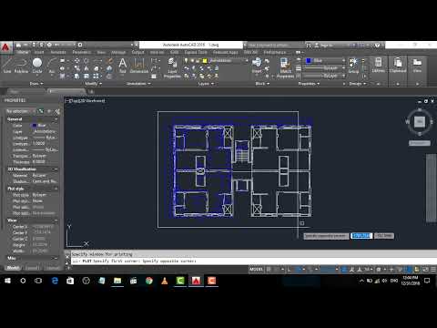
AutoCAD
- Click Output > Send panel > Export. At the Command prompt, enter export.
- In the Export Data dialog box, enter a file name.
- Under Files of Type, select Lithography (*.stl). Click Save.
- Select one or more solid objects. All objects must be entirely within the positive XYZ octant of the world coordinate system (WCS). That is, their X, Y, and Z coordinates must be greater than zero. The file extension .stl is automatically appended to the file name.
Autodesk Inventor
- Save Copy As
- Select STL
- Choose Options > Set to High
- Enter Filename
- Save
CADKEY
- File>Export>STL
- Type a file name and select OK
- Change format to binary
- Use default facet tolerance
- Additional export tolerance options are in the Solids99 Configuration window accessed from the Tolerance section of Configuration.
DataCAD
- In the File pull-down menu, select Export STL file.
- Click Save
Deskartes-3D Data Expert
- Transfer the data into 3Data Expert through IGES file
- Give command Solid/Triangulate in 3Data Expert
- A watertight STL file is generated
- Surface accuracy control during the process is easy
- To check for a good STL file:
- Orient surface normals and check for errors with Solid/Repair command
Google SketchUp
- Download Sketchup to DXF or STL plugin.
- To use the plugin, download the file below (skp_to_dxf.rb) to the Sketchup plugins folder on your computer. [VERSION] stands for the Sketchup version number (6, 7 or 8).
- On a Windows PC: If you’ve installed Sketchup on the C: drive, this folder will be at C:\program files\google\google sketchup [VERSION]\plugins.
- On Mac OSX: The sketchup plugins folder is /Library/Application Support/Google SketchUp [VERSION]/SketchUp/Plugins
- After copying this file, start Sketchup. You should now have an extra menu option (Export to DXF or STL) in the Sketchup Tools menu.
IronCAD
- Select Part Properties, then Rendering
- Set facet surface smoothing to 150
- Select File, then Export
- Select .STL
Mechanical Desktop
- Use the AMSTLOUT command to export your STL file.
- The following command line options affect the quality of the STL and should be adjusted to produce an acceptable file:
- Angular Tolerance: This command limits the angle between the normals of adjacent triangles.
 The default setting is 15 degrees. Reducing the angle will increase the resolution of the STL file.
 - Aspect Ratio: This setting controls the height/width ratio of the facets. A setting of 1 would mean the height of a facet is no greater than its width. The default setting is 0, ignored.
- Surface Tolerance: This setting controls the greatest distance between the edge of a facet and the actual geometry. A setting of 0.0000 causes this option to be ignored.
- Vertex Spacing: This option controls the length of the edge of a facet. The default setting is 0.0000, ignored.
- Angular Tolerance: This command limits the angle between the normals of adjacent triangles.
Pro E / Creo
- File > Export > Model (or File > Save a Copy)
- Set type to STL
- Set chord height to 0. The field will be replaced by minimum acceptable value.
- Set Angle Control to 1
- Choose File Name
- OK
Pro E Wildfire
- File > Save a Copy > Model
- Change type to STL (*.stl)
- Set Chord Height to 0.
 The field will be replaced by minimum acceptable value.
 - Set Angle Control to 1
- OK
Revit
Revit doesn’t allow direct export to STL files. First save in dwg file and open in AutoCAD to create STL files.
- Go to 3D view
- Go to File menu , select Export CAD format
- A dialog box opens
- Select Option
- Scroll down the dropdown menu (3D view only) and select 3D polymesh
- Select “AutoCAD 2004 DWG” in Save as type
- Next, open the saved file AUTO CAD
- Enter “Explode” on the command menu
- Select the object and press Enter
- All the objects are converted into 3D solid
- Select a single solid for STL output (must be one solid to export to STL)
- Enter “stlout” or “export” on the command menu
- Select objects: Use an object selection method and press Enter when you finish
- Create a binary STL file? [Yes/No]: Enter y
Rhino
- Open the model design in Rhino.

- From the File menu, select Save As. The Save dialog box opens.
- In the File name box, enter a name for the new STL file.
- In the Save as type box, select Stereolithography [*.stl].
- Click Save.
- In the STL Mesh Export Options dialog box (Simple Controls), set the STL tolerance – the maximum distance allowed between the surface of the design and the polygon mesh of the STL file.
- In the Polygon Mesh Detailed Options dialog box, set the STL tolerance in the field labeled Maximum distance, edge to surface
- Click OK.
- In the STL Export Options dialog box, set the file type as Binary and click OK.
NOTE: In order to build on additive manufacturing technologies, STL files must contain completely closed (watertight) polygon mesh objects. Refer to Rhino’s STL help for more information.
SolidEdge
- File > Save As
- Set Save As Type to STL
- Options
- Set Conversion Tolerance to 0.
 001in or 0.0254mm
 - Set Surface Plane Angle to 45.00
- Save
SOLIDWORKS
- File > Save As
- Set Save As Type to STL
- Options > Resolution > Fine > OK
- Save
NOTE: More detailed STL conversion steps for SOLIDWORKS are available »
Think3
- File>Save As
- Set Save As Type to STL
- Save
UGS NX 6
- File > Export > STL
- Set Output type to Binary
- Set Triangle Tolerance to 0.001
- Set Adjacency Tolerance to 0.001
- Set Auto Normal Gen to On
- Set Normal Display to Off
- Set Triangle Display to Off
Unigraphics
- File > Export > Rapid Prototyping
- Set output type to binary
- Set triangle tolerance to 0.0025
- Set adjacency tolerance to 0.12
- Set auto normal gen to on
- Set normal display to off
- Set triangle display to on
AutoCAD: All You Need to Know Before Getting Started
Published on July 8, 2022 by Carlota V.
AutoCAD enables the professional creation and editing of 2D geometry and 3D models with solids, surfaces, and objects. It is one of the most internationally recognized CAD software because of the wide variety of editing possibilities it offers. For these reasons, it is a tool widely used by architects, engineers and industrial designers, among others. Currently, the software is developed and marketed by Autodesk, a leader in the market of design, engineering and 3D animation software. Founded in 1982, Autodesk, a multinational company, began its adventure with the development of AutoCAD before moving on to other software solutions, some of which specialize in additive manufacturing.
The first version of AutoCAD included only a modifiable drawing and a limited set of functionalities. Despite its simplicity, it was at the time a real revolution as it allowed to replace traditional hand drawings with a digital drawings. The name AutoCAD refers to Autodesk of course but also to Computer Aided Design. Initially, the software was not designed for 3D design, it was only dedicated to two-dimensional modeling. AutoCAD has rapidly evolved: so what are its features today?
AutoCAD is one of the most popular CAD software on the market
How Does it Work?
AutoCAD software is available for MAC and Windows, and supported programming interfaces include ActiveX Automation, VBA, AutoLISP, Visual LISP, ObjectARX, and .NET. However, the type of interface to be used will depend on the programming needs and experience of the user. On the Autodesk website, we can see that AutoCAD software offers many different options depending on the type of user. Thus, one can choose specialized tool sets such as Map 3D, dedicated to mapping applications, Plant 3D for piping and instrumentation schematics, and finally AutoCAD Architecture for accelerating architectural design thanks to more than 8,000 available objects.
In AutoCAD, there are four types of 3D modeling. The first is wireframe modeling, where a three-dimensional structure is designed and used as a reference geometry on which various models and modifications are made. The second is the solid modeling where the user will be able to play with different masses. Surface modeling offers precise control of curved surfaces. Finally, mesh modeling allows the user to freely sculpt shapes, create folds and smoothing. The 3D models can be exported in .STL format, which allows them to be 3D printed.
There are 4 types of 3D modeling in AutoCAD
For those who are still in school, Autodesk also gives the option to purchase an educational version free for 3 years, which can be used on a maximum of two personal devices and is aimed primarily at students. In addition, the main versions allow all users to purchase a 30-day free trial period to discover all its functionalities. If by any chance you decide not to opt for this type of software, there are always alternatives, such as FreeCAD, Onshape or nanoCAD. In the following, we will explain the two main versions of AutoCAD, but it is important to mention that there is also a mobile version of the software.
Full AutoCAD, the Most Complete Version
Of course, the full version of AutoCAD includes all the features of the limited version, plus many more. It integrates a palette of industry-specialized tools to reach multiple disciplines such as architecture, mechanical and electrical engineering. It allows 3D modeling, rendering and point clouds capable of generating final products that users will be impressed with. It also provides individual and network licensing, ideal for teams as it does not limit to one license situation per person. In addition, unlike the LT version, this extended version allows export in .stl files for 3D printing. The price of this version is $235 per month, although if you decide to pay annually, the price will be $1865 which in the end is a lower amount than if purchased monthly.
Full AutoCAD is the most complete version and allows 3D modeling functions (photo credits: Autodesk)
AutoCAD LT, the Cheaper, More Limited Version
This LT version of AutoCAD is much more affordable than the full version, so it is normal to wonder what the difference is. The reason is that AutoCAD LT does not have a Z-axis in the drawing, or anything that uses it. This means that it has no 3D modeling capability, it only allows editing in two dimensions. Even so, it allows multiple functions. One of the main advantages of the LT version is its ease of use. It looks and works just like the extended version, but without the clutter of 3D modeling operations, among others. It is therefore ideal for people who are just starting out in this area and are looking to understand the basic commands of the software. The price of this version is $60 per month, having the option to contract a full year for $460, a little cheaper than if purchased monthly.
In conclusion, it is important to remember that, at its inception, AutoCAD was not created as a software dedicated to 3D design. In addition, it has many complex tools that make it difficult to use. Therefore, as it is not a software for beginners, we recommend other simpler software to get started in the world of 3D modeling, such as TinkerCAD. If you already have knowledge in this type of software and you are thinking of getting it, you can find more information on the official AutoDesk website HERE.
Have you used AutoCAD to create 3D printable models? Let us know in a comment below or on our Facebook and Twitter pages! Don’t forget to sign up for our free weekly Newsletter, with all the latest news in 3D printing delivered straight to your inbox!
Nidalee 3D Model STL DWG File・3D Printer Design Download・Cults
3D Model Prestige Star Guardian Syndra
2 €
Monster Tamer Veigar 3D model
1,50 €
Star Guardian Waist 3D model
1,50 €
Sindra's Withered Rose 3D Model
1. 50 €
50 €
Oozaru Vegeta
1,50 €
League of Legends Yuumi 3D Model
2 €
Spirit Blossom Yone 3D Model
1,50 €
Chi Chi (Adult) - Dragon Ball 3D Model
1,50 €
Future Trunks 3D Model
1.50 €
Janemba (Fat + Super) Dragon Ball 3D Model
1,50 €
Elder Dragon League of Legends 3D Model
2,50 €
Perfect Cell - Dragon ball Z 3D Model
1,50 €
Best 3D printer files in Game category
Lost Colony: Spaceship Graveyard – Internals Basics
15. 54 €
54 €
Secret design
Simple V-tail quad copter
Free
Articulated Wolf Wally from Toon Blast Print on site
1.01 €
Functional Spiderman Web Shooter
Free
Kong's in a Barrel
2.02 €
Tiny stag beetle (Dorcus rectus)
Free
Bestsellers in the Game category
Healer conversion kit SM
6 €
Off-road vehicle
2 €
Space Dwarf All - terrain vehicle
16.20 €
Altair Amberwatch
10. 12 €
12 €
Vodfolk Explorer
10.12 €
Heavily armored warriors Catafrac - set of limbs
1,85 €
Snake and rattlesnake
4.04 €
Articulated tarantula
4.04 €
Exolotreftes Truescal
5 €
Heavy Imperial Fire Support Weapon [Preliminary Support]
5 €
Mouse in a cheese box
4.04 €
Dancing Skeleton
3.54 €
Cute flexi unicorn
1.05 €
SPACE GNOME SQUAD
6.07 €
Lev Fu
5. 50 €
50 €
RC 1/10 Dodge Challenger
7,50 €
Do you want to support Cults?
Do you like Cults and want to help us continue our journey on our own ? Please note that we are a small team of 3 people, so supporting us in maintaining activities and creating future developments is very easy. Here are 4 solutions available to everyone:
-
AD: Disable your AdBlock banner blocker and click on our banner ads.
-
affiliation: Shop online by following our affiliate links here Amazon.
-
DONATIONS: If you want, you can donate via PayPal here.
-
* INVITE FRIENDS: * Invite your friends, discover the platform and great 3D files shared by the community!
3D printing: quick tips for moving from a CAD model to a printed object
Nadezhda 06/12/2020 Useful, Articles 0
Whether it's just a hobby or a source of income, 3D printing is always based on product design. Those accustomed to traditional technologies will have to rethink the entire approach to product design and manufacture.
When the project is ready, a number of additional operations are performed: setting the orientation of the model and other parameters that ensure the proper printing process. In addition, it is necessary to take into account the fact that most 3D printers allow you to choose the degree of filling the model with cellular structures. The correct choice of this parameter provides protection of the object from deformation and destruction during the printing process, as well as significant savings in material and reduction in production time.
Finally, the last factor influencing the success or failure of the 3D printing process is the strength of the connection between the model and the table. If the workpiece is separated from the table during printing, then all the work will go down the drain.
Here, we'll walk you through the 3D printing process and provide some simple guidelines for using additive manufacturing in the design phase. In addition, we will dwell on the methods of preparing a finished project for printing, and also consider ways to securely fasten the workpiece to the table.
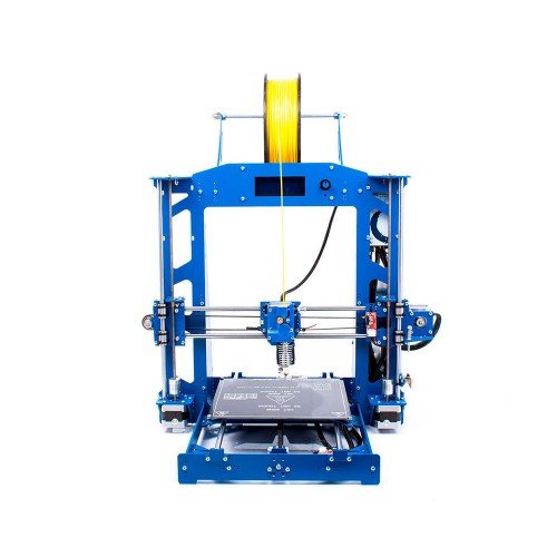
These guidelines apply primarily to Fused Deposition Printers (FDM) printers, but may apply to other types of printers. The process of obtaining a finished part by 3D printing is basically the same regardless of the method used.
Designing an object
Any 3D printing starts with construction. If you are developing a product yourself, then you need to build a 3D model of it in a computer-aided design (CAD) system to turn the designer's idea into reality. In this case, the object can be both very simple and very complex. However, too thin and too small models should be avoided.
Save the file in a special format for printing
To print an object, its model must be saved in a special file format - for example, STL, which has become the de facto standard in the world of 3D printing.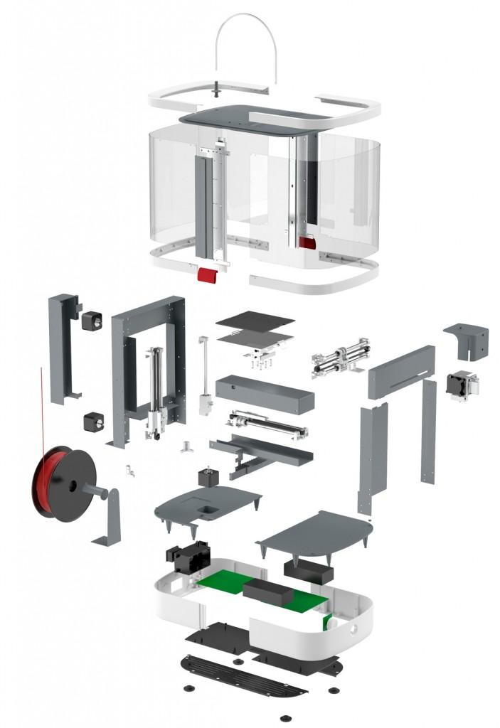 In this format, model surfaces are represented as a grid of triangles. Simple surfaces are broken down into a small number of triangles. The more complex the surface, the more triangles you will need. Today, other formats are used in 3D printing, in particular, the 3MF format developed by Microsoft. But the most common is still STL.
CAD systems make it very easy to save the model in the desired format: just execute the command Save as . To improve print quality, it is desirable to set a number of settings for saving to the STL format - for example, the tolerance during transformation and the angle of the plane. The lower the conversion factor and the better the angle, the smoother the printed part will be.
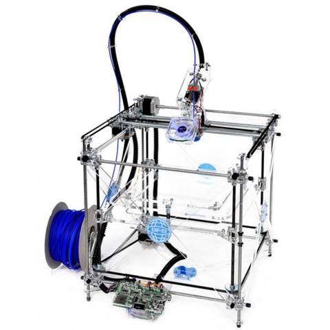
Opening the file in the slicer program
Most, if not all, 3D printers come with their own slicer software. The slicer loads the STL file created in the CAD system and cuts it into layers, and then creates a control program for the printer.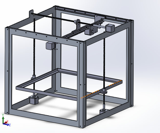
Positioning the model correctly in the print space
After entering the print settings, the model (or several models) needs to be placed on the printer table. You can print many objects on one table at once. At the same time, compared to printing a single object, the time slightly increases, but in general it still turns out to be less. Here are some tips for choosing the right model orientation.
Set parameters
In the slicer software, the user sets parameters such as print speed, media consumption, nozzle and desktop temperatures. Most slicers have simple settings for beginners. In this case, most often there are also advanced settings so that experienced professionals can achieve optimal results. Advanced settings include percentage infill, amount of backing material, and type of backing or raft (this is a small, thin base that keeps the printed part stable. The backing is removed when it's finished). The number of options is truly endless.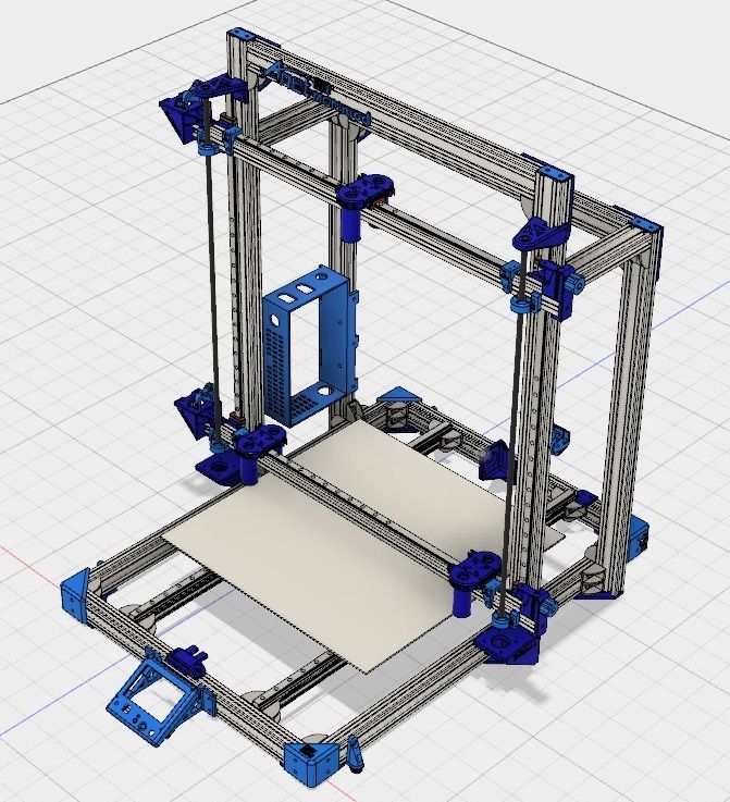 Specific settings vary depending on the brand of printer. It's easy enough to set them up.
Sending the control program to the printer
After setting the print parameters, the placement of future objects on the table, their orientation and quality, it's time to finally start the printer. Just press the button Print and find something to do while the production is in progress. Depending on the complexity of the design, the process takes from several minutes to several hours.
Finishing
Finishing includes the removal of the printed part from the table, as well as the removal of the support material by melting, mechanical separation or dissolution (depending on the design of the printer). The part may require some light sanding or polishing, but overall a properly printed object looks good from the start. Other types of finishing are placing plastic parts in a container with acetone to smooth out surface roughness, gluing (if the dimensions of the structure exceed the dimensions of the 3D printer or individual elements of the object must have different orientations), drilling holes and painting.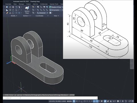
3D printing process
3D printer design considerations
Eliminate sharp corners
If the direction of the surfaces changes abruptly (for example, a vertical wall intersects with a horizontal floor), then this model is difficult to print. The printer will build excessive inner surfaces, wasting too much material. There are two easy ways to prevent this: add chamfers to smooth out where the surfaces meet, or round the corners so the printer gradually builds a vertical surface. In addition, rounding will increase strength, since destruction most often occurs at sharp corners.
Elimination of thin walls and small geometries
Fused fusion technology consists in feeding hot plastic through a nozzle to form the printed object layer by layer. The thickness of the extruded plastic layer cannot be made smaller than a certain limit, depending on the diameter of the nozzle and the speed of the print head. Excessively thin-walled details are difficult to print - often the result is a chaotic weave of fibers. If the part can be printed, it is very fragile and breaks easily.
Too thick walls - also bad
On the other hand, if the walls are too thick, they become brittle and crack easily. This is especially important when printing from materials other than resins, as excess thickness during the manufacturing process leads to internal stresses in the part. Even when printing from plastics, material is wasted on walls that are too thick and time is wasted.
Removing large overhangs
3D printers can create amazing shapes and surfaces, but they can't print directly in the air. If there is a void in the part with material above it, additional support material must be used. Most slicers add material automatically, but require you to specify the orientation and volume of the support structure. Printers with a single nozzle create an array of thin columns, which then have to be broken off. The result is an uneven surface. Therefore, it is recommended to avoid large overhanging elements whenever possible in order to reduce the need for support material.
If such an element is unavoidable, you can try to flip the object. Most printers are capable of printing overhanging elements with an angle of about 45 degrees. At a certain height, the edge of such an element may sag somewhat. The actual capabilities of a particular printer are determined by trial and error.
Holes shrink
Remember that the part is made of heated plastic. As it cools, it inevitably shrinks. Therefore, holes and other critical structural elements have to be made larger so that after shrinkage their size is as close as possible to the required one.
However, if a tight tolerance hole needs to be made, it is best to print it to a smaller diameter and then ream it with a suitable tool. This is especially true for holes whose axis is parallel to the printer table.
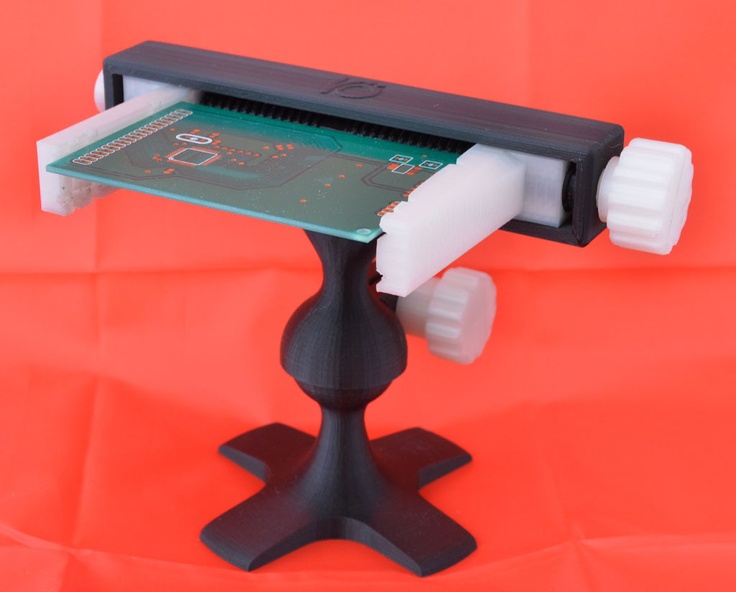
Increasing the footprint
If the area of contact between the object and the base is small, the part may separate from the table during printing. To prevent this from happening, wide bases are added to the model legs, which are installed on the printer table. In general, the closer to the table, the more material must be added to the support. There are other ways to securely fasten the part to the table, which we will discuss a little later.
Special moves
The right approach to design makes printing easier. In addition, there are special post-processing techniques that are important to be aware of.
Place round surfaces vertically
The model should be oriented so that the minimum amount of support material is used. Ideally, it should rest on the table with a large flat edge. In addition, circular geometry must be placed so that the circular faces are vertical. If we look at the printer table from above, we should see a round silhouette of the object. In this case, the part comes out as symmetrical as possible with the formation of a solid round structure.
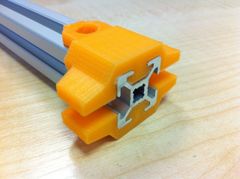
Place voids and holes vertically
If there are voids in the model (for example, it is a rectangular pipe), it is desirable to place such voids vertically in order to reduce the amount of support material. If you print the pipe in a horizontal position, you will have to provide support for the entire inside. If you put the pipe on the end, then no support is required at all.
The same is true for holes: to get a hole with a straight axis, it is best to print it vertically - in the form of a stack of rings, which avoids warping or deforming a round hole into an oval one.
Set print quality settings
Proper selection of print parameters, such as STL conversion tolerance and slicer software settings, allows parts to be produced with surface quality that matches that of cutting. However, this entails an increase in print time. When choosing quality parameters, one should proceed from the purpose of the object: is it a finished product or a prototype? Will the part be visible or hidden?
The quality parameters also affect the shape of the holes in the part. In CAD files, holes are represented as a set of straight lines at an angle to each other. The higher the quality of the model in the saved STL file, the less the circle looks like a polygon.
Reducing the layer thickness
To obtain the best quality, especially when using layered deposition technology, it is necessary to reduce the thickness of the layers. It does increase the print time, but the end result is worth it!
Optimizing the filling with honeycomb structures
Objects do not have to be solid from a strength point of view. Similar to a honeycomb, printers can create a honeycomb infill that balances strength and saves expensive polymer material. However, if the printed part serves as a prototype for strength testing, and the serial product will be manufactured by traditional methods, and also if the part is subjected to certain types of mechanical stresses and pressures, a solid design will be preferable.
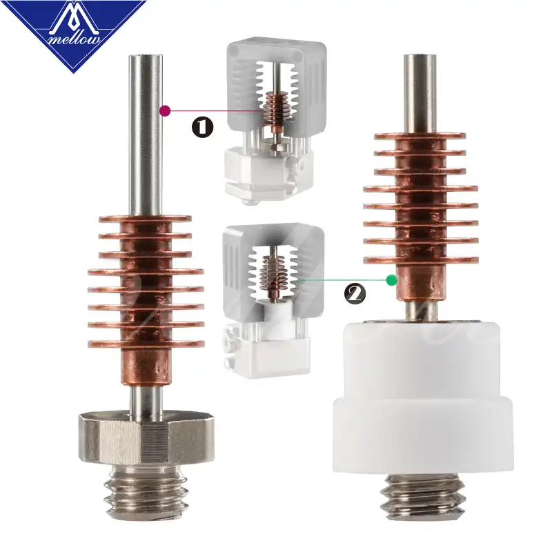
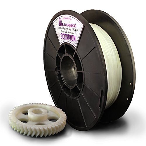
Choosing material
Printing success depends largely on the correct choice of media. Materials have different properties. For example, the melting point of thermoplastic polyurethane (TPU) and polylactic acid (PLA) is lower than that of acrylonitrile butadiene styrene (ABS). In addition, the material is taken into account when choosing the type of support structures. For an object made of polylactic acid, supporting elements can be made from the same polylactic acid, since it will be quite easy to separate them from the finished part. If the part is printed from ABS plastic, then the support elements must be made from a different material, and it is better not to use such elements at all in thermoplastic polyurethane parts.
Cellular filling
A solid body is not always the best choice for 3D printing. Printing solid parts has its advantages, but the internal honeycomb structure saves both expensive material and time.
Creation of objects with a given degree of filling with cellular structures is a unique possibility of three-dimensional printing. Moreover, it is not required to design such a structure: this is done by the slicer program. As a rule, it is enough to set only the percentage of filling (the closer it is to 100, the more solid the object will turn out) and select the type of cells, if the printer has such an opportunity.
In addition to saving time and material, the internal honeycomb structure has many other advantages.
Cellular filling prevents warping
Printing large objects in one piece causes warpage hazard. By reducing the infill percentage, the air during printing passes through the part, providing more uniform cooling and eliminating warpage.
Cellular filling does not lead to loss of strength
Printing cells instead of solid material does not reduce the strength of the part. In many cases, a honeycomb part is strong enough for the chosen application, but lighter and less material intensive.
The function determines the selection of cell geometry
Most slicers support a wide variety of cell geometries. The optimal option is determined by the functional purpose of the object. Standard box padding simplifies printing, while hexagonal and triangular boxes add strength. Wave fill allows the object to bend or twist.
How do I choose the right filling percentage?
In general, the strength of an object increases as the infill percentage increases. Most printers have a default infill percentage of 20, which is optimal in some cases but too high or too low in others. Consider mechanical stresses in the printed object and increase the percentage of infill in areas where greater strength is required. If high strength is not required, choose the lowest possible filling. This saves material and speeds up printing. Most often, the selection of the optimal percentage of filling is done by trial and error.
Ways of fastening the workpiece to the table
"Rafts", "brims", "skirts" - these terms sound funny, but they just refer to the three main ways of attaching a 3D printed part to a printer table. Let's take a look at each of these methods and their areas of application.
Skirt
The skirt involves creating a few rings around the object at the start of the print to make sure the plastic extrudes normally. The skirt is not in contact with the object at all. It surrounds the printable area and helps start the fusing process. When creating a skirt, a large volume of hot thermoplastic polymer passes through the nozzle. This prepares the printer for printing the part itself. This guarantees good adhesion to the table and obtaining smooth surfaces of the object.
Brim
A brim is a wide, flat area connected to the main object as a support base (think of a brim of a hat). It is very similar to a skirt, but connected to the model. In addition to all the advantages of a skirt, the brim keeps the edges of the object being made on the table.
When printing, the outside of an object often cools faster than the middle, causing the edges to curl. Brim prevents this phenomenon by holding the edges.
Raft
The raft is a detachable base, made in the form of a thin mesh platform, located under the entire object (which lies on the raft). To create a raft, the printer first prints a flat plate in two or three layers, and then begins to manufacture the object.
Rafts provide excellent adhesion to the table surface and also serve as a strong base for printing. This is especially useful when making small and oddly shaped parts that do not fit well on the table, as well as thin-walled objects.
After printing is complete, in most cases the raft will separate easily from the part.
If the printer does not have a heated desktop function
Rafts are used if the printer does not have a desktop heater. In this case, excessive adhesion becomes a problem.
An alternative method is to apply adhesive paper tape to the printer platform, wrapping the edges down if possible (this also protects the platform itself). You can also use packing tape, but it is usually more expensive.
If buckling does occur, or if the object separates from the table, apply soluble glue stick to the adhesive tape. This will enhance adhesion.
Find out the features of a specific 3D printer and take them into account when preparing your model
Three-dimensional printing is not only a science, but also an art. Effective design for subsequent 3D printing requires an understanding of the technological process, taking into account its features and the purpose of the future object. This will greatly improve print performance.
Use of Solid Edge in 3D printing
Not all CAD systems are suitable for 3D printing
The capabilities of the applied system should not limit designers. Our Solid Edge® system is designed with the latest 3D printing technologies in mind. Various 3D printers and 3D printing services are supported.
Take it to the next level with specific techniques for designing 3D printed parts
Generative modeling in Solid Edge opens up new possibilities: the designer selects a specific material, sets the design space, allowable loads, restrictions and target mass of the part, and the system automatically calculates the desired geometry. As a result, 3D printing methods can produce the most complex shapes.
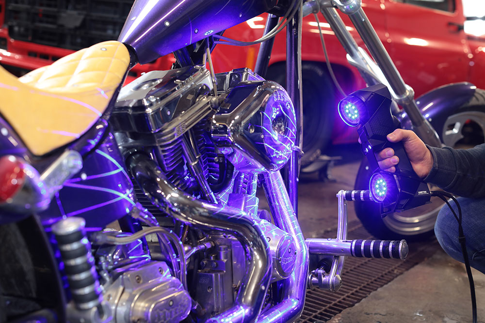
In addition, when building models, the use of the results of three-dimensional scanning is provided. Solid Edge successfully combines the traditional boundary representation of solid models (B-Rep) and the representation of surfaces in the form of a grid of triangles, which avoids time-consuming transformations that are fraught with errors.
If you've already downloaded the STL file for printing, our unique synchronous technology allows you to quickly and easily edit your imported models in Solid Edge in preparation for the process.
Print with your own printer or submit an order to a 3D printing service provider
Printing in Solid Edge on a local 3D printer is done with the command 3 D print . Models can be saved in STL and 3MF formats, or sent directly to Microsoft 3D Builder. If you don't have your own 3D printer or need to try out different materials and surface finishes, Solid Edge allows you to directly submit your models to cloud-based 3D printing services (such as 3YOURMIND). You immediately receive quotes for the production of parts from various materials with its subsequent delivery directly to your door.