Diy heatbed 3d printer
DIY 3D Printer from scratch — Heated bed | by Daniel Faegnell | 3DPrinterChat
Welcome to 3DPrinterChat.com, this article is part of the DIY 3D Printer from scratch, and you will learn a bit more about how the Heated bed works.
What is a heated bed and how it works?
The heated bed is a device that should provide a warm surface to the plastic stick, heated-beds have a huge advantage against warping and other adhesion issues when compared to cold beds. The heated bed have the heating element and the surface material, that can be glass, aluminium or the heating element itself.
The heating element works by converting electrical energy into heat, this happens when electric current flows through an resistance or non-ideal electronic, the amount of energy converted into heat is measured in watts. for example, an ordinary heated bed produces about 80W of heat.
There are two main kinds of heated beds, the printed circuit board and the resistor bank, since the resistor bank is not used due its disadvantages, we wont cover it, but here is a image of how it looks.
How a PCB Heated bed works
The heated bed is made using the printed circuit board concept, which is basically a board (which is usually made of glass or fenolite) with a thin layer of copper on one side (or even multiple layers), then this board is printed or treated in a way that will protect some lines of copper, and leave the rest exposed, then this copper will receive a treatment with acid to remove the parts not protected, this process will leave us with only the useful circuits and connections,
Those tiny lines of copper will behave like an resistor (remember that everything in the universe poses some resistance to electrical flow, and this resistance is dissipated as heat), When we connect those “wires” to a power supply will we will generate heat, exactly what we were expecting.
The PCB has the great advantage of using a small amount of space when compared to other kinds of heating elements, it also can contain multiple layers, which will increase the power/cm² dissipated dramatically.
If properly designed, the printed circuit board is capable of distributing the heat more efficiently than any other kind of heated bed, since the power distribution can be drawn and simulated.
Heat distribution and why it matters
See these two examples below:
[caption id=”attachment_15225" align=”aligncenter” width=”501"]
First example: Heated bed without heat distribution correction[/caption]
[caption id=”attachment_15246" align=”aligncenter” width=”502"]
Second example: Heated bed without heat distribution correction and weird behavior[/caption]
[caption id=”attachment_15224" align=”aligncenter” width=”501"]
Third example: Heated bed with heat distribution correction[/caption]
As you can probably guess, a deficient heat distribution is bad, but why is it bad? For materials with high “warping rate”, or technically speaking: with high contraction propensity. These temperature differences will create opposite forces (contraction and expansion), that will force the material to bend, see the image below:
[caption id=”attachment_15295" align=”aligncenter” width=”554"]
Source: https://goo. gl/lIvCgV[/caption]
On the first example, we have a cold bed, you can see the red area which the nozzle has just passed by, and the heat it leaves behind, this is likely to cause warping. On the second example, with the heated bed, we can see that the printed part is also hot, this will reduce the contraction and expansion forces because the temperature difference is lower (ΔT), this part is not likely to have issues with warping.
Now that you understood why a proper bed heat distribution matters, i’ll take as example the famous MK2 Heated bed
RepRap MK2 | $14–18
The MK2 Heated bed is by far the most used heated bed on the DIY community, it is an printed circuit board heated bed, which has the advantage of being capable of handling 12 or 24v just by changing the wires position.
Bed dimensions: 200x200 mm (heated area)
[caption id=”attachment_15302" align=”aligncenter” width=”430"]
Mk2 heating from 60ºC to 110ºC[/caption]
[caption id=”attachment_15303" align=”aligncenter” width=”430"]
Mk2 Holding 60ºC[/caption]
Final judgement:
The Mk2 is a good and cheap bed, for lower temperatures the heat distribution is fair, but is good to mention, if you will print something with the maximum allowed size (200x200) on a material that can be printed with 60ºC (like PLA) the warping propensity is smaller than a material that needs 110º (like ABS).
Improving my current bed
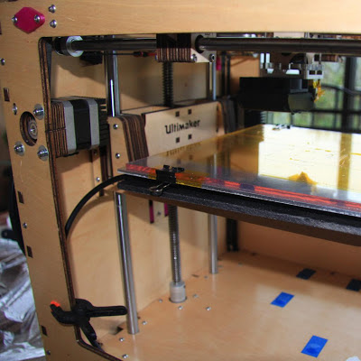
If you don’t want to replace your current heated-bed, there are some workarounds, like adding a glass on the top of the heating element, 3–5mm gives the best result. (keep in mind that this will slow down the heating process, but it also will makes the temperature distribution better)
Example image of a MK2 with 4mm glass. source
Credits and Sources:
All this work would not be possible without the awesome posts below, consider visiting them!
SD3D — Not all heated beds are created equal
RepRap — Heated_Bed
3D Printing Systems — Warping
Heavily Modified or Homemade 3D Printer Heated Bed Connection Repair
Written By: Stephen Luu (and one other contributor)
- Favorites: 0
Difficulty
Moderate
Steps
8
Time Required
30 minutes
Sections
1
- Heated Bed 8 steps
Flags
0
- BackHomemade 3D Printer
- Full Screen
- Options
- History
- Download PDF
- Edit
- Translate
- Embed This Guide
-
Remove the four screws from the corners of the panel covering the controller board.
-
This may be found in various places of the printer depending on the model of the printer. Refer to the user manual or trace back wires from the heated bed.
-
The most common areas include: mounted on the side of the printer, underneath in the base of the printer, and inside an externally located control box.
Edit
-
Locate the heated bed and temperature sensor connectors.
-
Here on the MKS Gen L V1.0 it is labeled H-BED and TB for Heated Bed and Thermistor Bed. Refer to a Pinout Diagram for your specific board.
-
Common boards include: Creality V1/V2, MKS Gen L V1.0/V1.4, MKS BASE V1.4, Einsy RAMBo, SKR v1.3/v1.4.
-
Remove the connection for the heated bed.
-
Remove the connector for the temperature sensor.
Edit
-
Remove four thumb nuts from the corners of the heated bed.
-
Use a screwdriver if needed to hold screws in place while removing the thumb nuts.
-
Remove the heated bed from the Y-carriage.
Edit
-
Desolder the damaged cable or connector.
-
For tips on soldering, check out the How To Solder and Desolder Connections guide.
-
Take note of the polarity and which is for power and the thermistor. You may wish to take a picture for future reference. Red is for '+', Black is for '-'.
-
Do not use force to remove the cable or connector; doing this may rip the pads out.
-
Work in a well ventilated area when soldering; a fume extractor is recommended.
Edit
-
Remove the old solder by using a solder pump or solder wick.
-
Re-tin the pads with fresh solder.
-
Use isopropyl alcohol to clean up any residue around the connections.
Edit
-
Strip 1/4" from both ends of the wire and tin.
-
Check out the following guide for help with stripping wires: Wire Stripping.
-
Solder the wire onto the heated bed.
-
It is safe to bridge the connection if both pads are of the same polarity.
-
If your bed has a built-in LED, polarity will matter, otherwise it does not matter. Polarity does not matter on thermistor.
Edit
-
Apply Kapton Tape over the connection.
-
Solder an XT60 connector to the other end of the wire.
-
How to Use Heat Shrink Tubing
-
Terminate cables coming from the controller board with an XT60 connector as well.
-
If polarity matters, take note when soldering the XT60 connector.
Edit
Edit
Author
with 1 other contributor
Badges: 2
Team
heating connection, from which to make heating from 220 volts
Depending on what plastic will be used during printing, heating of the 3D printer desktop may be required. In addition, budget devices do not always have such a function. Therefore, many make a heating table with their own hands.
Heating table for 3D printer
The heating table is a working surface consisting of several layers, one of which has a heating element. On the heating table and prints the printer.
The heater usually has a serpentine pattern.
Why is heating needed?
The use of a heated bed during 3D printing is a simple and reliable way to protect finished products from uneven cooling, which often causes deformation of the part. Even on the cheapest printer, you can get good quality models using a heated work surface.
How to make a table for a 3D printer with your own hands?
Types of heating tables:
- Textolite. This is the most affordable option. The textolite table consists of a textolite plate with copper tracks applied to it. Most often, they are powered by 12 or 24 V. Direct printing on a textolite sheet will not work, since it is quite flexible and deforms during heating.
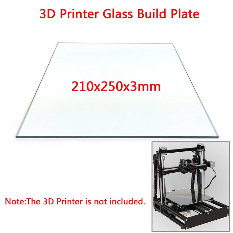
 Glass is attached to it from above to stiffen and level the surface.
 - Aluminium. Textolite is also used in aluminum tables, but instead of glass, an aluminum sheet is laid on top.
- Silicone. Can be flexible or rigid, depending on the design. It consists of a heating element, which is filled with heat-resistant silicone.
Step-by-step instructions
The easiest way to make a table is based on silicone. To do this, you will need to prepare the following materials:
- nichrome wire with a diameter of 0.2 mm;
- sheets of cardboard;
- mounting tape;
- nails with small head;
- glass;
- heat resistant silicone sealant.
Manufacturing process:
- Several sheets of cardboard are stacked on top of each other and held together with adhesive tape.
- An ordinary checkered sheet is attached with the help of studs.
- Hats are recessed and aligned.
- Tape strips are glued on the sides (next to the caps).
- The studs are carefully pulled out so that everything stays in place.
- The paper is also carefully removed.
- Glass wiped with alcohol. After that, the resulting design is glued to the glass. First you need to glue one strip, and then the second with a stretch.
- Everything is generously lubricated with heat-resistant sealant (except adhesive tape). The layer must be at least 2 mm.
- After drying, the adhesive tape is removed and the empty spaces are also smeared with silicone.
- A wire is soldered to the end of the wire to connect to the network.
Mistakes and how to avoid them
It is important to correctly calculate the length and thickness of the wire. Otherwise, there will be either overheating (which will lead to a short circuit or burnout of the wire), or too little heating. For calculations, you can use special online calculators. They include the required power and voltage of the network.
Making your own heating table for a 3D printer is quite simple. All materials are available. Home-made manufacturing is especially important for those who have budget printer models.
- March 28, 2021
- 3987
Get expert advice
We make a heated table for the MC2 3D printer with our own hands
We make a heated table for the MC2 3D printer with our own hands
We make a heated table for the MC2 3D printer with our own hands
3 was presented in one of the previous articles
3 printing technology with ABS plastic on the cold table of the MS2 3D printer from Master Kit. And what if we make this table heated and adjustable, eliminating the AUTO_BED_LEVELING function?
https://masterkit.ru/blog/articles/delaem-podogrevaemyj-stol-dlya-3d-printera-mc2-svoimi-rukami
With pleasure experimenting with the MC2 printer and refining it, I came to the conclusion that it was time I wish I had a heated table. There's more that the printer's electronics support this feature. And at the same time try to make this table adjustable by eliminating the AUTO_BED_LEVELING function. In principle, the function works well, I wrote about this in this article, but I wanted to try this option as well.
Actually, for this you need to purchase only the heater itself, the thermistor and springs for adjustment - this can be done on the website 3d.masterkit.ru. And figure out how to thermally untie the plastic parts of the printer, designed to mount the table, and the heater.
After rummaging through the cupboards, I found a piece of fiberglass.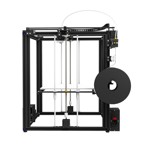 Good, smooth, 2 mm thick. I sawed off a square 220x220 mm from it. (Heater size - 214x214 mm) And, without thinking twice, I drilled 4 holes in it for M3x10 screws with a sunk head for fastening the textolite to standard glass holders and 4 holes for mounting the heater. I drilled holes of 2.5 mm in the details for fastening the glass and screwed the textolite with screws like self-tapping screws.
Now you need to attach the heater to the textolite through the springs. For a while I thought about how to make sure that the nuts of the adjusting screws were fixed, but then I decided to do without nuts at all. I cut the M3 thread directly in the fiberglass, it turned out somewhere around 4 turns. I tried several times to screw in and unscrew the spring-loaded screw. If you do this carefully, the thread holds well, does not deform. Let's see how the solution will behave during long-term operation; if the thread deteriorates, I will stick a metal nut-washer with an M3 thread on the textolite, you can print a retainer from ABS, or something like that.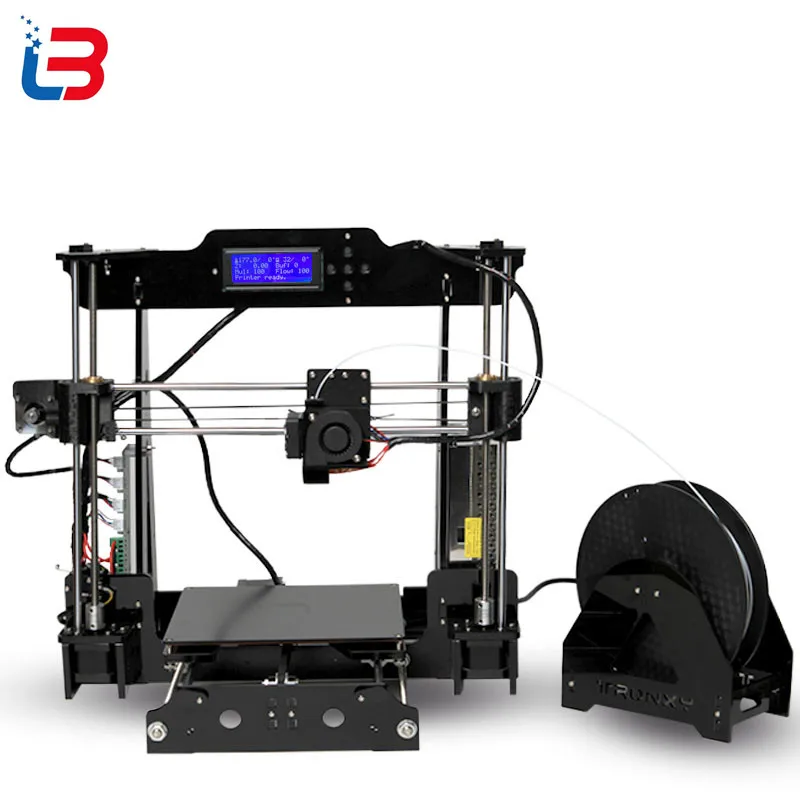
Next, glue the thermistor into the central hole in the heater with heat-resistant tape or paper tape. It connects to the control board at connector T1. Also in the Marlin firmware, you must allow reading data from this sensor. To do this, in the Configuration.h tab, you need to change 0 to 1 in the line #define TEMP_SENSOR_BED 1
After that, in the RepetierHost program, you can see and set the table temperature value.
Printing glass - how could it be without it - it is convenient to fix it with stationery paper clips. You can find them in any stationery department. This is how the sandwich turned out. Pretty hefty, I must say. I decided that it would be necessary to reduce in connection with this acceleration along the Y axis, and at the same time X. We climb into the firmware again. And we halve the following parameters in Configuration.h (new values are indicated):
#define DEFAULT_MAX_ACCELERATION {4500,4500,100,9000}
#define DEFAULT_ACCELERATION 1000
Probably a little slower typing, oh well, we're not in a hurry.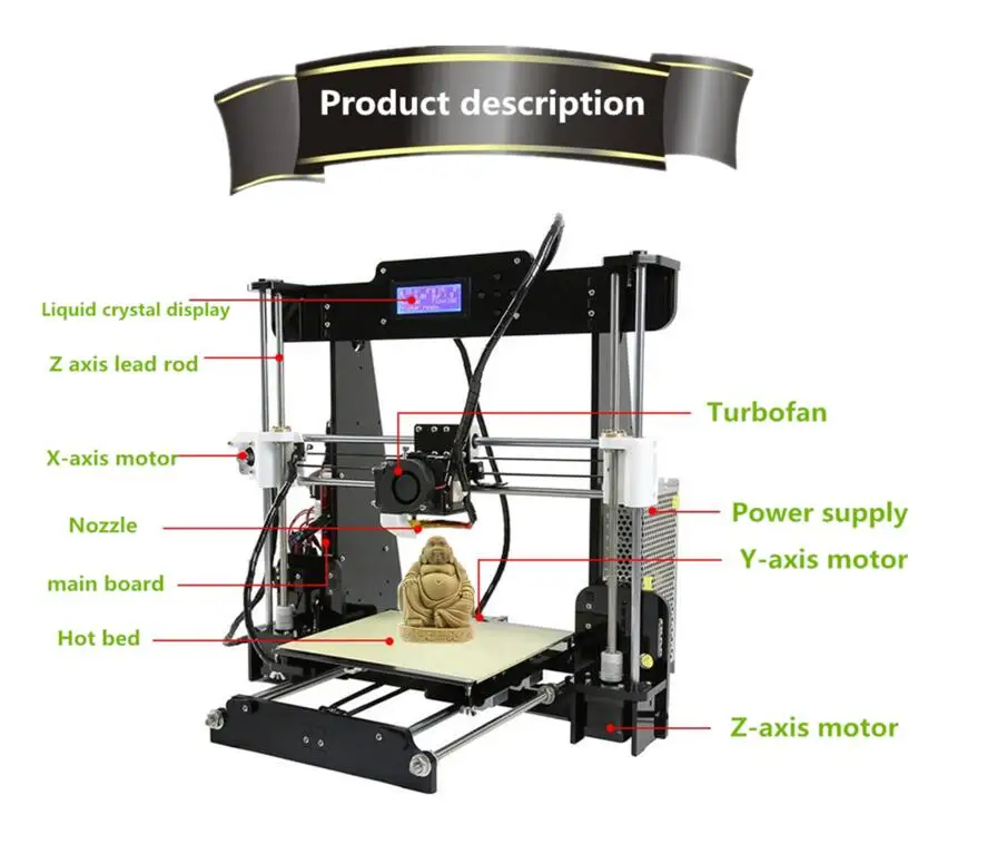
In order to eliminate the influence of the extruder mounting on positioning accuracy and to fully realize the possibility of adjusting the table, I decided to rigidly fix the extruder in its holder, for which I drilled through the details of its fastening and tightened it with screws. In this regard, I had to rearrange the Z-axis limit switch under the platform on which the X-axis is implemented. I printed a part with two slots for adjusting the limit switch and simply glued it with dichloroethane to the base connecting the three stepper motors from the bottom of the printer. Just in case, I also tightened it with a screw. Now the limit switch is triggered when the platform is lowered to the desired level.
As a power supply, taking into account the current consumption increased by 10A (!) I used an ownerless power supply from an old computer with a power of 350W. It gives 15A current on the 12V yellow wire. The heater is connected to the terminals D8 of the control board.