Diy 3d printed injection mold
How to Mold Plastic Parts In-House
Injection molding is ubiquitous as a manufacturing process—in fact, the majority of plastic products in the world today are manufactured by injection molding. While it is an ideal technique for large-scale production needs, traditional CNC machined metal molds have prohibitive high costs and long lead times for low-volume production.
For prototyping and low-volume production (approximately 10-1000 parts), 3D printed injection molds provide a time- and cost-efficient solution. They also enable a more agile manufacturing approach, allowing engineers and designers to test mold designs, easily modify them, and then continue to iterate on their designs much faster, while being orders of magnitude cheaper than traditional CNC machining.
Creating custom molds using a stereolithography (SLA) 3D printer, like the Form 3+, is simple and convenient, allowing you to leverage the benefits of both 3D printing and traditional molding techniques.
In this guide, we’ll walk you through the process of DIY injection molding and share all the tools and tips necessary to utilize plastic injection molding in-house using 3D printed molds.
For detailed guidelines, design recommendations, and real-life case studies, download our white paper.
White Paper
Download our white paper for guidelines for using 3D printed molds in the injection molding process to lower costs and lead time and see real-life case studies with Braskem, Holimaker, and Novus Applications.
Read the White Paper
Building a setup for DIY plastic molding does require some investment. It takes both money and time to acquire the right equipment and to master using it. However, these costs are in many cases still lower than the cost of a single metal mold, so the eventual time and cost savings, once you’re up and running, will easily offset the initial effort.
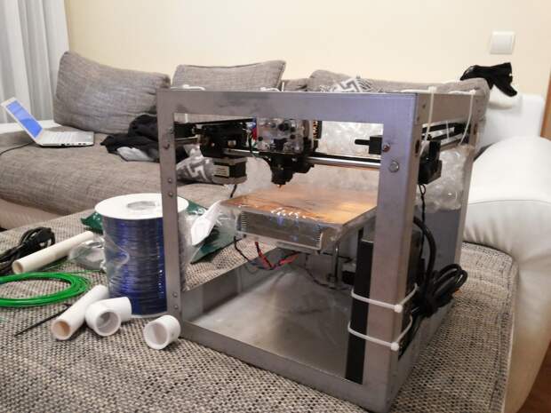
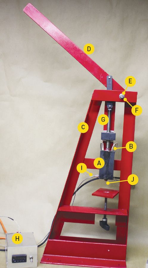
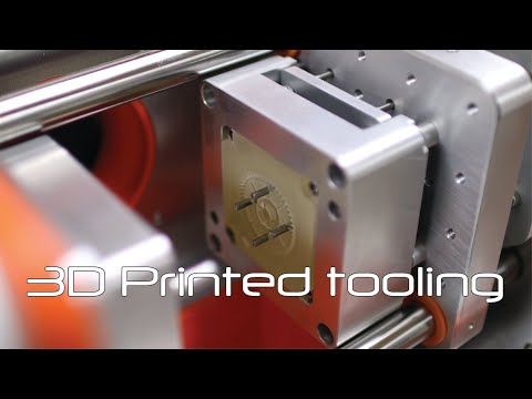
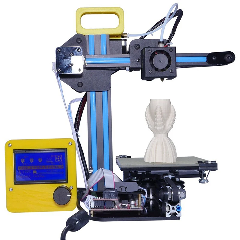
The Form 3 SLA 3D printer next to a Holipress desktop injection molder.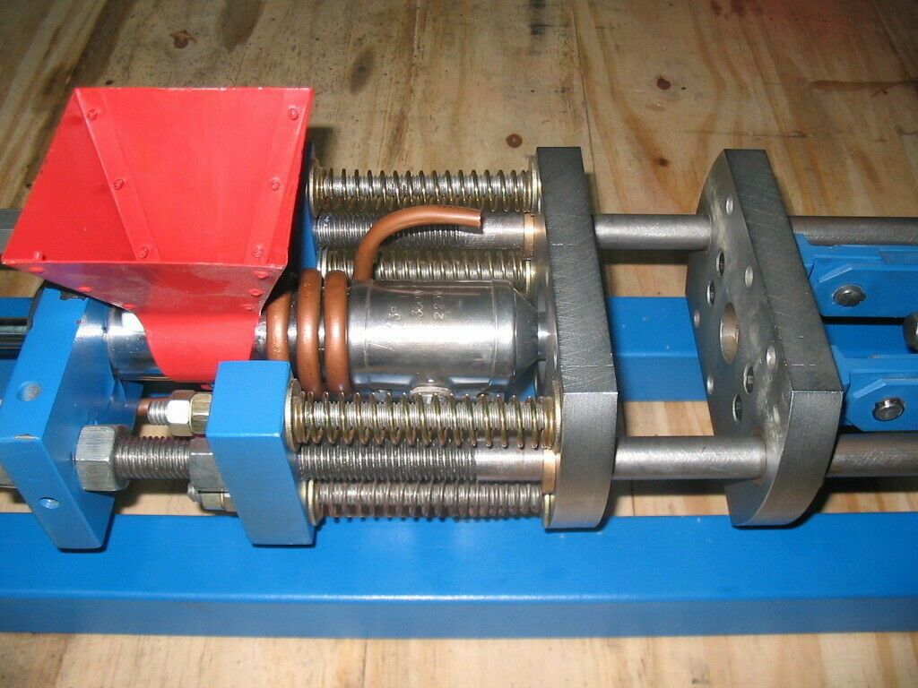
Here’s what you’ll need to get started:
-
A high-performance desktop SLA 3D printer, like the Formlabs’ Form 3+. The Form 3+ can produce accurate molds with crisp features, and a smooth surface finish that will yield high-quality final molded parts. Beyond DIY plastic molding, an SLA 3D printer is also a valuable asset for prototyping and other applications throughout product development.
-
A 3D printing material that can withstand the temperature and pressure on the mold during the injection molding process. We recommend the following materials for Formlabs SLA 3D printers:
-
Rigid 10K Resin is an industrial-grade, highly glass-filled material, which provides a solution that can cope with a wider variety of geometries and injection molding processes. It has an HDT of 218°C @ 0.45 MPa and a tensile modulus of 10,000 MPa, making it strong, extremely stiff, and thermally stable.
-
High Temp Resin offers a heat deflection temperature is 238 °C @ 0.
 45 MPa that is suitable for injection molding. This material is more brittle, but is recommended for materials with a high molding temperature and to reduce cooling time.
 -
Grey Pro Resin has a lower thermal conductivity than High Temp Resin or Rigid Resin, which leads to a longer cooling time, but it is softer and can wear hundreds of cycles.
-
-
A benchtop injection-molding machine, such as the Galomb Model-B100 or the Holipress. There are a number of benchtop injection molders on the market that vary in cost. Many of the lower cost molders use a hand-driven plunger, while some of the more expensive units use a screw or pneumatic system. Some of our customers have recommended systems from Minijector, Morgan, APSX, or Micromolder as well. Desktop automated molders such as the product line from Babyplast are good alternatives for mass production of small parts.
-
Plastic pellets of your choice
-
A CAD software tool of your preference to design the mold insert, such as Blender, which you can download for free.
Before purchase, make sure to evaluate the injection molder carefully against your production requirements. For large parts, industrial processes will still be necessary. This DIY injection molding technique is best optimized for producing small parts at low volumes.
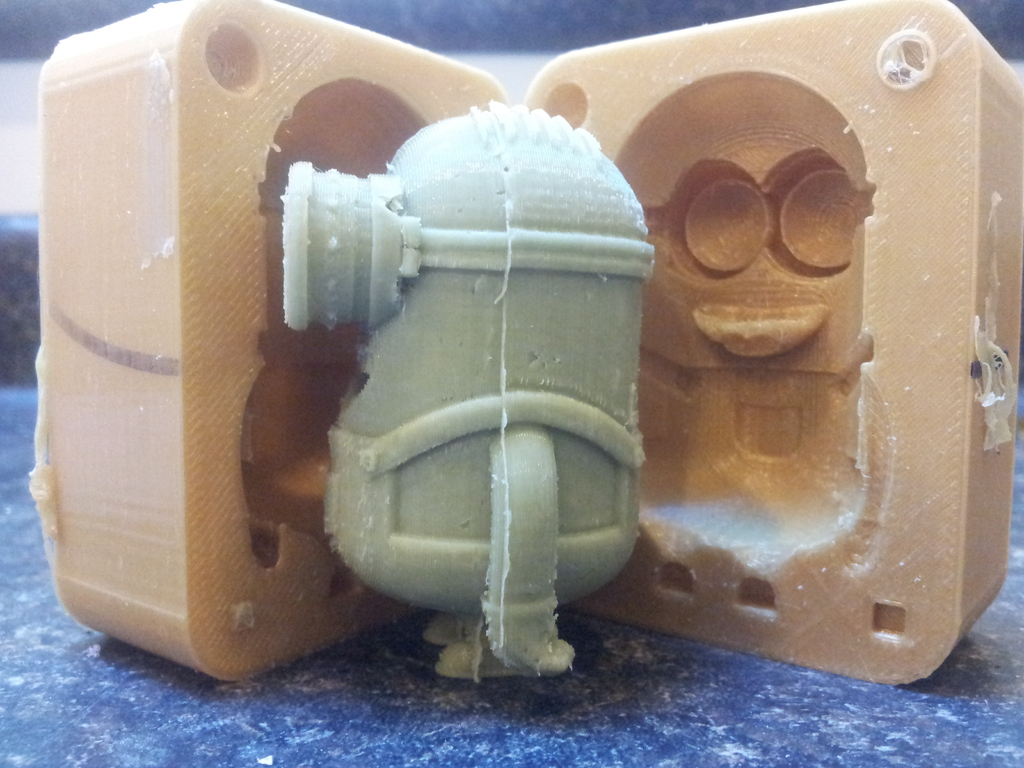
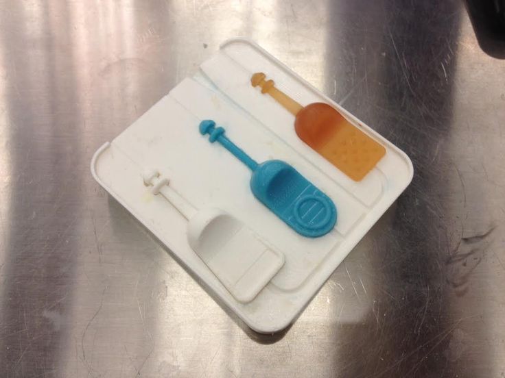
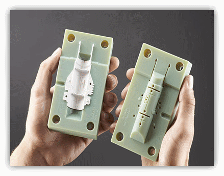
A Formlabs 3D-printed mold, and encapsulated component, made using this DIY injection molding process.
Webinar
In this webinar, we'll show you how to use stereolithography (SLA) 3D printed molds in the injection molding process to lower costs, reduce lead times, and bring better products to market.
Watch the Webinar Now
First, pick the CAD software tool of your preference to design the mold insert. We’ll use the open-source Blender, but the workflow should be fairly similar in any other CAD software.
Download the blank mold insert design files—you’ll use them to create your injection mold design. The designs can also be easily scaled to accommodate most injection molders and mold frames.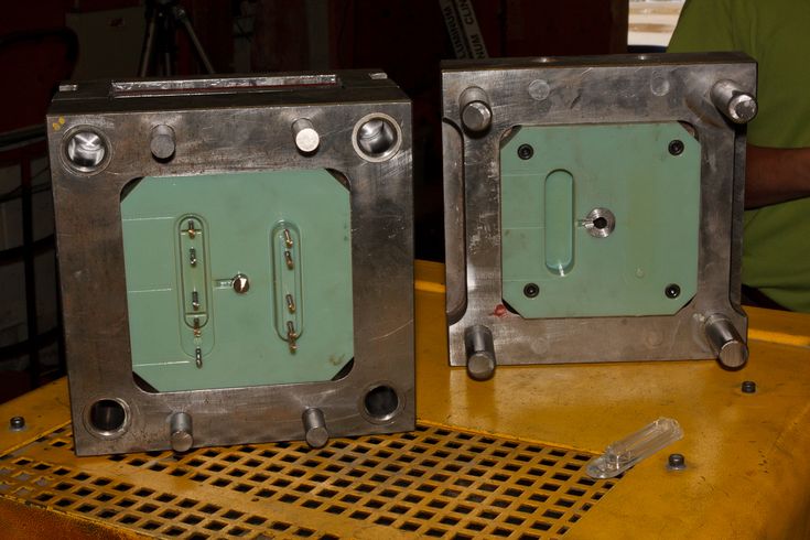 Alternatively, you can also design your own mold insert for the using the cavity diagrams of the master mold frames.
Import both mold halves of the mold core and the 3D design you’d like to produce into your CAD tool.
In Blender, use the eye icon in the scene explorer to toggle off one half of the mold. Once your workspace is set up to your liking, set both halves of the mold to the “wire” draw type under the Object menu, as in the image below.
Now, you can position your mold. Ensure that the object fully intersects with the inlet for the molten plastic during the injection molding process. Use orthographic mode, engaged via “toggle perspective/ortho,” to make this more straightforward.
Turn the visibility of your current mold core off, and turn the other side on. Repeat the process to ensure that the object fully intersects with the inlet of the other half of the mold core. With your object lined up, you’re ready to subtract the area of two intersecting objects by using the “boolean difference” function in Blender.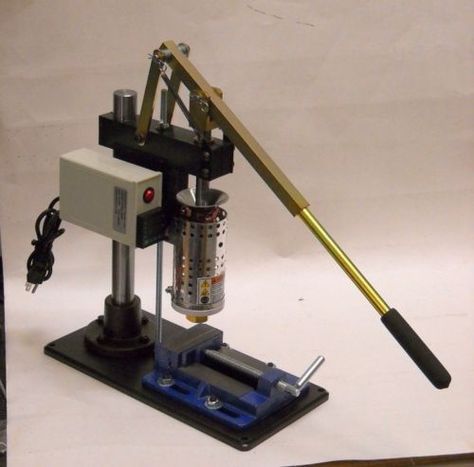
Select the first half of your object, and choose the boolean option under the Modifiers Menu. Select the object you’re cutting, and make sure that the “difference” operation is selected. Apply the operator, and do the same for the other side. It should look something like the image below. If you get stuck here, this tutorial on adding interlocking components to a design may be helpful.
Your mold is now ready for printing. Export each half, making sure to check the “Selection Only” box in the Blender exporter.
To 3D print the mold, it’s essential to pick a material that can withstand the temperature and pressure on the mold during the injection molding process.
Based on internal testing and case studies with our customers, we suggest to choose the 3D printing resin based on the criteria from the table below. Three stars means the resin is highly effective, one star is less effective.
| Criteria | High Temp Resin | Grey Pro Resin | Rigid 10K Resin | |
|---|---|---|---|---|
| High molding temperature | ★★★ | ★ | ★★ | |
| Shorter cooling time | ★★★ | ★ | ★★ | |
| High pressure | ★ | ★★ | ★★★ | |
| Increase cycle number for complex geometries | ★ | ★★ | ★★★ |
Setting up the print only takes a few seconds in PreForm, the print preparation software for Formlabs 3D printers.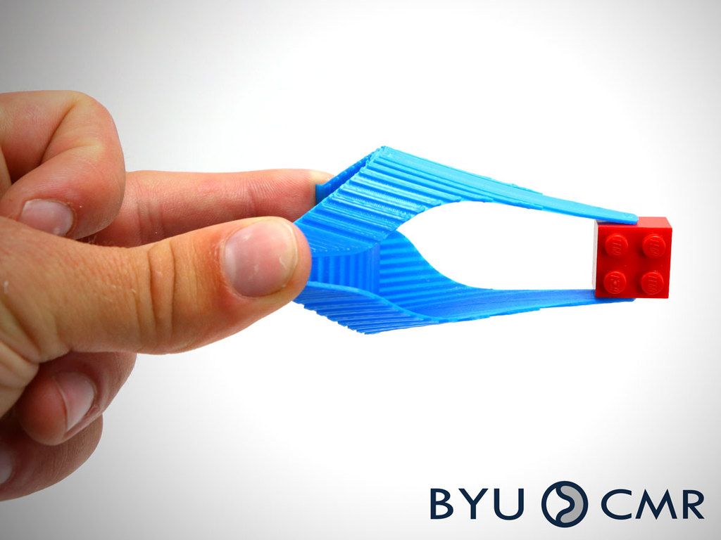 If your mold design requires support structures for printing, make sure to orient the mold halves in PreForm so that the cavity faces up. This will simplify post-processing and ensure a high-quality surface for your molded parts.
Depending on the geometry and the size, multiple molds can be printed at once on a build platform to increase printing efficiency.
Now that you’ve designed and 3D printed your mold, you can mold the parts on your benchtop plastic injection molding machine.
You have a wide variety of materials to choose from for injection molding. Formlabs and our customers have tested the following materials with 3D printed injection molds:
- LDPE
- PP
- PA
- PE
- TPE
- TPU
- PLA
- ABS
- ASA
- HDPE
- EVA
- PS
- POM
Consider the desired properties of your object and the capabilities of your injection molder before you make your choice. From there, simply follow the bespoke instructions on your injection molder to quickly and efficiently produce your parts.
Depending on the injected material, adhesion of the part to the mold can cause deterioration of the mold during extraction, in particular with flexible materials such as TPUs or TPEs. Using a mold release agent is a good solution to help separate the part from the mold. Silicone mold release agents are compatible with Formlabs Grey Pro Resin, High Temp Resin, and Rigid 10K Resin.
If you have more questions about the workflow, make make sure to check our article FAQ: Injection Molding With 3D Printed Molds.
When designing your mold, consider what will 3D print successfully, as well as what will mold successfully.
The exact approach to DIY injection molding will vary based on your desired design and volume, but these tips and tricks will help increase your success rate.
-
To reduce the visibility of print lines on the finished part, print the mold with a smaller layer height (50 or 25 microns per layer instead of the default 100). Note that this increases print time.
-
Adding two to five degrees of draft on surfaces perpendicular to the direction of pull will allow the part to be removed more easily and will minimize degradation of the mold.
-
You can polish split-plane surfaces with fine-grit sandpaper to reduce flash.
-
Consider using a water bath to more rapidly cool your part and reduce warping.
-
Embossed and engraved details should be offset from the surface by at least 1 mm.
-
If designing for an aluminum mold frame, add .125 mm of extra thickness to the back of the mold plates to account for compression forces and to ensure a complete seal.
For the complete process workflow and other best practices, download our white paper.
White Paper
Interested in other applications of 3D printed molds? Download our white paper that also covers thermoforming and casting with elastomers.
Download the White Paper
The conversation around 3D printing and injection molding is often oppositional, but it’s not always a question of one versus the other. By directly 3D printing parts or using 3D printed molds for injection molding for prototyping and low-volume production, you can leverage the benefits of both technologies. This will make your manufacturing process more time- and cost-efficient and allow you to bring products to the market faster.
Want to learn more about injection molding with 3D printed molds? Download our white paper for detailed guidelines for using 3D printed molds in the injection molding process and see real-life case studies with Braskem, Holimaker, and Novus Applications.
Download the White Paper
3D printing low-run injection molds
This article discusses the use of 3D printing to print molds for low run injection molding. Design considerations, materials, molds configurations and a comparative case study are all included
Introduction
Injection molding is the most common method for mass producing plastic parts.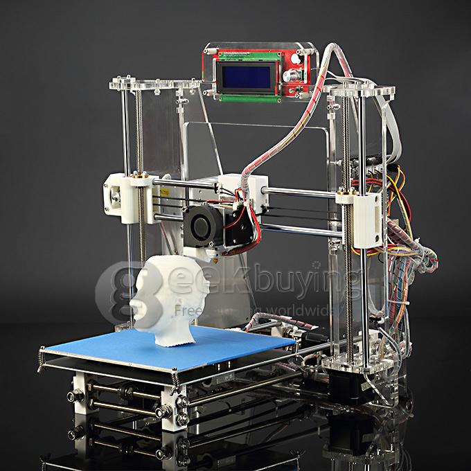 It is ideal for producing rapidly very large numbers of identical parts with tight tolerances.
In the past, 3D printing was used in the design and manufacturing process to only create and verify prototypes that would be later injection molded. Nowadays, technology developments in printer accuracy, surface finish and materials allow 3D printers to also directly manufacture the molds.
This article discusses the benefits of using 3D printing for manufacturing low-run injection molds and gives advice on the possible mold configurations, the available 3D printing mold materials and the best design practices for creating 3D printed injection molds.
📍 Please note: Hubs does not manufacture 3D printed molds, but does manufacture custom injection molded parts
What is injection molding?
Injection molding is the process of creating a components by injecting under pressure melted material into a die. The material fills the hollow cavities of the mold and when it cools it solidifies, taking the form of the die. The die then opens, the solid part is ejected and the process repeats. Automating the this process can yield very high production rates. The materials commonly used in injection molding are thermoplastic polymers, but it is possible to mold certain thermosetting plastics.
The high initial setup costs associated with injection molding make this technology cost-effective only at high volumes. These costs can range between $10,000 and $100,000 and are associated mainly with the very high requirements in designing, engineering and manufacturing the injection molding dies. Because of this injection molding is typically only used to produce very high volumes of identical parts at a low cost. A typical run can involve the production of thousands or sometimes millions of components.
The term low-run injection molding typically applies to runs of 10 - 100 parts. Traditionally, such small runs were not financially feasible due to the very high costs associated with manufacturing the tooling (the injection molding dies).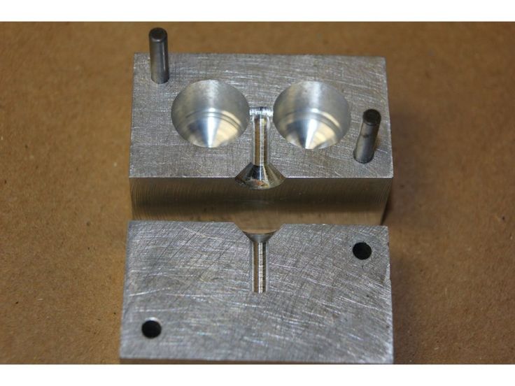
Why use 3D printing?
It is important to consider whether a mold is going to be used to make 20 or 20,000 parts. Historically molds needed to be CNC machined to a very high tolerance from metal (most commonly aluminium or steel). These materials provide good wear resistance to the repeated injection, opening and closing of the mold and the temperature gradients that they were exposed during the injection molding process. However, metal molds do require a initial large investments at the setup stage.
For low-run molding, wear resistance is no longer the most critical factor. Certain 3D printing technologies, such as Material Jetting and SLA, are able to produce parts to a high accuracy with excellent surface finish. When this is coupled with the modern temperature resistant 3D printing materials and the design freedom 3D printing enables, it means that 3D printed molds are now a viable option for manufacturing low-run injection molding dies.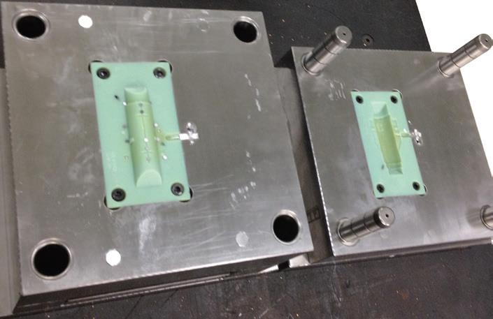 3D printed molds also allow the quick verification of the mold design, mitigating the financial risk of investing in an expensive metal mold.
3D printed molds are best suited for:
Fast turnaround times (1-2 week opposed to 5-7 weeks).
Applications where production quantities are low (50 - 100 parts).
Mold designs where changes or iterations are probable.
Parts that are relatively small (less than 150 mm).
3D printed mold configurations
3D printed injection molds are produced in 2 standard configurations:
Mold inserts in aluminium frames: This is the most common 3D printed mold configuration and generally produces more accurate parts. The mold is 3D printed and then inserted into rigid aluminium frames which provide support against the pressure and heat of the injection molding nozzle.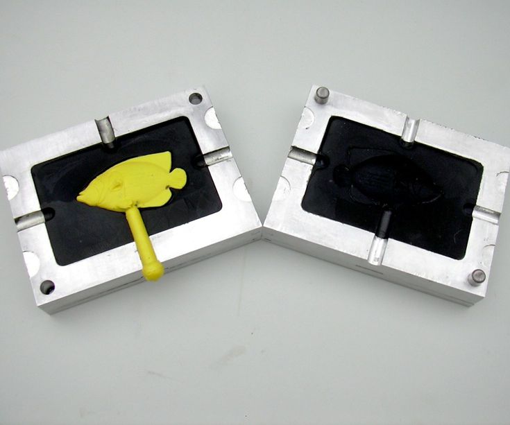 Aluminium frames also help preventing the mold from warping after repeated usage.
Stand alone molds: In this mold configuration the mold is fully 3D printed and a rigid aluminium support frame is not used. This way intricate cooling channels can be integrated in the mold, but molds manufactured using this approach require more 3D printing material (increasing the print cost and time) and are more prone to warping after extensive use.
A 3D printed injection mold inserted into an aluminium support frame(image courtesy of Formlabs)
Materials
A 3D printing material is suitable for creating injection mold if it has:
- High temperature resistance - A high heat deflection temperature is required to withstand the mechanical and thermal loads applied to the mold during material injection. Note though that the temperature decreases rapidly during solidification.
- High stiffness/toughness - Repetitively removing parts can cause wear to the mold, so materials with high stiffness are required to maintain mold accuracy over time.

- High level of detail - One of the main requirements of an injection mold is high dimensional accuracy and a smooth surface. Highly accurate molds will produce highly accurate parts.
The 3D printing technologies that cover best these requirements are SLA and Material Jetting. These technologies can produce parts with high dimensional accuracy and are ideal for prints intricate details and very fine features. Speciality materials that are available in these technologies, like Formlabs High Temperature resin or Stratasys Digital ABS, are ideal for molding and tooling applications. An outline of the properties that are most relevant to injection molding for these two materials is shown below.
For industrial applications, desktop SLA is not suitable. An in-depth article comparing the two most commonly used industrial 3D printing materials for mold manufacturing (Digtal ABS and Somos PerFORM) can be found here.
| Property | Formlabs High Temp resin* | Stratasys Digital ABS** |
|---|---|---|
| Heat deflection temperature | 289 ℃ @ 0.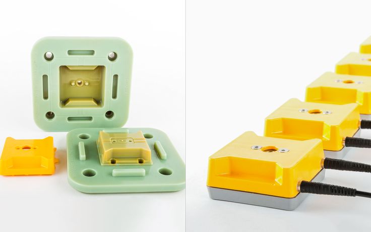 45 MPa 45 MPa | 92 - 95 ℃ @ 0.45 MPa |
| Flexural modulus | 3.3 GPa | 1.7 - 2.2 GPa |
| Impact strength (Notched IZOD) | 14 J/m | 65 - 80 J/m |
| Lowest layer height (resolution) | 25 - 50 microns | 16 - 30 microns |
| Minimum detail size | 0.2 mm | 0.2 mm |
Mold Design
Describing specific technical design of mold features (such as gates, runners, air vents etc) is out of the scope of this article. An internet search will reveal a large amount of information on the subject. This post by Seattle Robotics is a good starting point for those new to injection mold design.
Here is a list of some good practices that should be followed when designing a 3D printed mold:
- When designing the mold for SLA printing, ensure that the inner faces of the mold are orientated so that no support is in contact with them. This will improve their surface quallity, as no support marks will present on these surfaces, minimizing the required post processing.
- Including shallow air vents (0.05 mm deep) from the edge of the cavity to the edge of the mold will help expel trapped air during the molding process.
- If the 3D printed mold is to be used for more than 20 runs, consider including channels in the design for embedding metal rods or tubes. These can help reinforce the mold, reduce warpage and improve cooling times.
- 3D printing the mold at a lower layer height can help produce smoother molded parts as the molds will have less visible print lines.
- Embossed and engraved details should be offset from the surface by at least 1 mm.
Specific restrictions on design will depend upon the injection molding machine that is used. However Stratasys suggest that molds made via their Material Jetting printers should be used to produce parts with maximum volume of 165 cm3 in 50 to 80 ton molding machines or manual hand presses.
Designing parts for injection molding
As with conventional injection molds, a designer should consider:
- Adding a draft angle of minimum 2o degrees to aid in the removal of the part from the mold.
- Maintaining a uniform wall thickness across the entire part.
- Keeping all walls and features as thin as possible.
- Including radii on all edges and corners.
- Including thin ribs and gussets to add strength to a part rather than increasing wall thickness.
Learn more about the importance of draft angles in this article →
Reducing Flash
Flash is the name given to the material that comes out between the two halves of the mold during the injection process.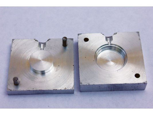 This generally occurs when the two mold halves do not mate perfectly together, are not perfectly flush and flat or the mold is overfilled. Runners are used in the mold design to help reduce the likelihood of flash.
If designing for an aluminium frame, add 0.125mm of extra thickness to the back of the mold plates to account for the compression forces and to ensure a complete seal. Increasing the clamping force in the vise can also help mitigate flash, as can polishing the molds' split plane to give it as flat a surface as possible.
Good mold design and a flat mold face reduce the likelihood of flash occuring(image courtesy of Formlabs)
Release compound
Due to the relatively fragile nature of the materials used in 3D printed injection molds compared to traditional molds, applying excessive force to remove a part from the mold can lead to rapid mold deterioration. Including a release compound on the surfaces of the mold cavity before the injection stage can assist greatly with part removal.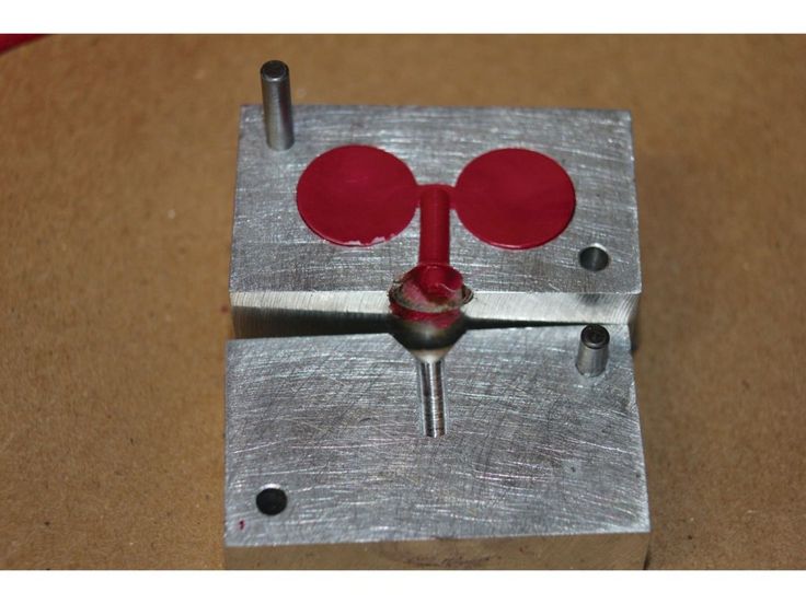
Case study: a plastic motor fitting
This case study will compare manufacturing a custom plastic fitting for a motor housing. The requirements of the design are:
- The total number parts is 25.
- A high level of dimensional accuracy in needed to ensure a tight fit.
- The weight of the part is 0.005 kg (5 grams).
- The part must be made from ABS.
- The part must be black in colour.
- The overall diameter of the part is 40 mm.
Here are the available alternative manufacturing options:
Industrial FDM ABS 3D printing: Industrial FDM 3D printing has high repeatability and can produces parts with high dimensional accuracy and is able to print parts in small to medium batches. The cost of the ABS filament used in industrial FDM systems is typically around $90 - $110 per kg. The main restriction for any part produced via FDM 3D printing is its anisotropic mechanical performance: parts are significantly weaker in one direction.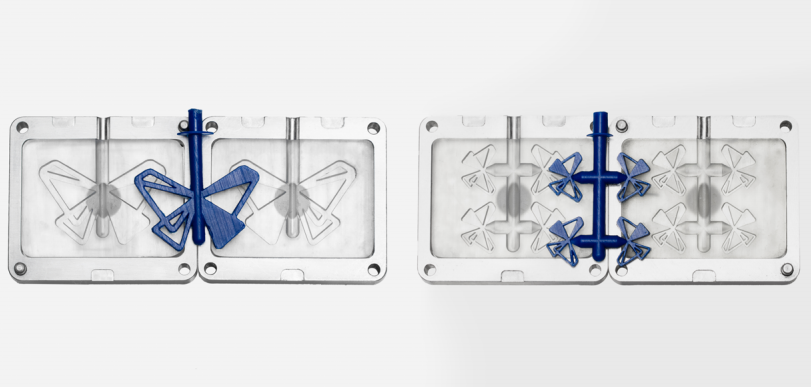 This means that a designer must have a good grasp on the loads the part will be subjected to and the orientation of the model in the print platform.
Injection molding ABS parts with SLA 3D printed molds: High Temperature SLA resins are able to produce functional injection molds with a high level of accuracy that are best suited for low level production runs. SLA resins retail at around $150 - $170 per litre. A benchtop injection molding machine has been used for the calculations in this example with the 3D printed molds inserted into aluminium support frames. ABS pellets are used for molding the part that cost approximately $2 - $3
Traditional injection molded ABS part: Traditional injection molded parts have a very high level of accuracy, excellent surface finish and a very high level of repeatability. The main downsides of traditional injection molding is the high initial setup cost and the number of design restrictions enforced in the designing of the molded part (draft angles, constant wall thickness etc). The cost of the ABS pellets is the same as above.
A summary of the cost (based on online quotes) of manufacturing the ABS fitting using the technologies discussed above is summarised in the table below. All prices do not include shipping.
| Industrial FDM* | 3DP IM** | Traditional IM*** | |
|---|---|---|---|
| Cost of mold | N/A | $70.85 | $1660.72 |
| Cost per part | $3.69 | $0.05 | $1.89 |
| Total cost | $92.25 | $72.10 | $1711.48 |
| Lead time | 4 days | 2 days | 8 days |
 com with Formlabs High Temp resin printed on a Form2 *** Quote sourced from Protolabs
 Next steps: How to produce parts with injection molding
Is low-run injection molding with 3D printed molds the best solution for your application? Then there are two ways for you to move forwards with you project:
If you have access to an injection molding machine and the know-how to design the mold, then 3D printing the mold in a heat resistant material is an option. An article discussing the advatages and disadvatages of the two most commonly used 3D printing materials for manufacturing low-run injection molds can be found here.
Otherwise, you can outsource the production to a professional injection molding manufacturer. Hubs offers access to a global network of Injection Molding service providers, who are able design a mold for your part and produce volumes from 100 to 10,000+ units.
Need advice on your injection molding project?
Speak with an expert
Rules of Thumb
- 3D printing the injection molds is the most cost effective way for low-run injection molding.
- Material Jetting and SLA are the most suited technologies for 3D printing injection molds.
- Use wide draft angles (2o degrees or more) and a release compound to increase the lifetime of the molds.
- Keep the part volume lower than 165 cm3
- Each 3D printed mold can be used for approximately 30 - 100 runs (depending on the material being injection molded).
Ready to transform your CAD file into a custom part? Upload your designs for a free, instant quote.
Get an instant quotetechnical study from a leader in the plastics industry
The French Industrial and Technical Center for Plastics and Composites - IPC, conducted a study evaluating the performance of injection molding using 3D printed molds. This article summarizes some of the findings, particularly those related to Formlabs 3D printers.
Injection molding is an economical and highly reproducible technology mass production of plastic parts with tight geometric tolerances. However, the high cost of traditional steel equipment makes it difficult to injection mold small batches of parts and can often be a barrier to new product introduction. By using 3D printed injection molds, engineers, fabricators and product designers can lower their costs, reduce lead times and bring better products to market. 3D printed injection molds are a great option for those who want to develop functional prototypes from end-use materials, produce a series of identical pre-production samples, or even custom or limited-edition end-use models.
Checkpoints
The IPC study was divided into three phases:
1 . Comparison of 3D printing technologies: The first classification was based on the technical data of several manufacturers. The thermal and mechanical characteristics were evaluated, respectively, in terms of deformation heat resistance (HDT) and tensile modulus. To select the three most promising materials for each of the identified technologies, four types of control points were developed to highlight critical properties.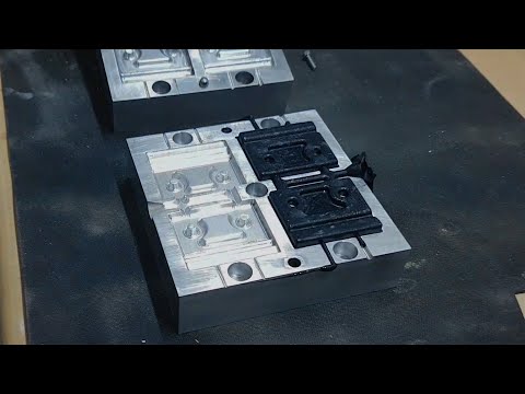 Due to the high resolution and smooth surface of the 3D printable models, resin-based solutions have been recognized as the best material choice for injection molding molds.
In general, a similar range of dimensional variations is measured for all considered 3D printing technologies: from ± 0.02 mm to ± 0.05 mm for small parts and from ± 0.05 mm to ± 0.2 mm for large parts .
The standard accuracy of machined metal tools should be ± 0.02 mm. This accuracy is desirable for a good fit along the parting line and to prevent reflow. IPC offers two methods for optimizing the parting line of a 3D printed resin tool.
2 . Guidelines for material characterization, design, and 3D printing.
3 . Injection mold test: IPC performed two tests with different mold sets. In the first test, an "extreme test" scheme was used. Nearly a hundred polypropylene models were cast using a mono-material mold printed in High Temp Resin. The second test used a more complex "extreme test" scheme.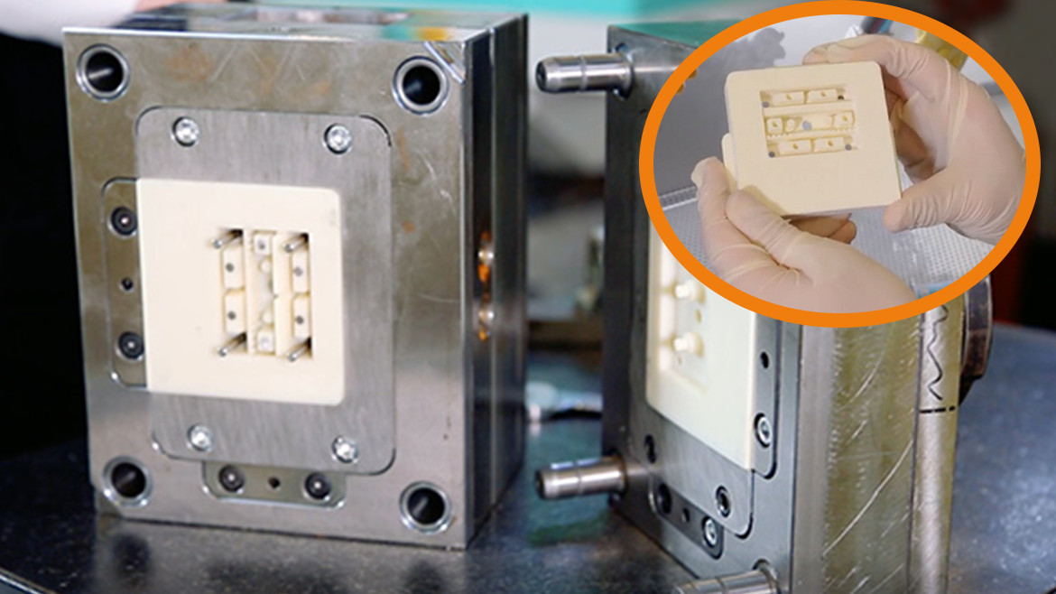 Thousands of polypropylene models were molded using a mold of different materials: the core and mold inserts were printed from Rigid 10K Resin, and the frame was printed from Nylon 12 (Polyamide 12) using selective laser sintering technology. 9Mold design from several materials with inserts (Fig. 2).
IPC has developed two sets of molds for casting two different complex patterns. Both sets were intended to optimize the quality of the parting line:
both halves of the tool must be positioned within a tolerance of ± 0.02 mm to ensure a correct fit.
1. Monomaterial mold printed in High Temp Resin.
It has a simple geometry with no inserts or additional moving parts, and includes texturing. To improve the parting line, it will be redesigned in the final stage.
Monomaterial mold STL file printed with High Temp Resin and loaded into PreForm software. Fixed side (left) and movable side (right).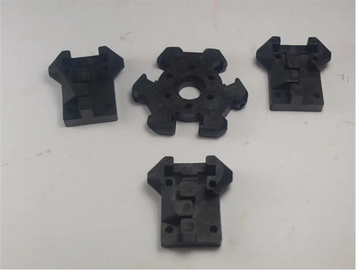
2. Multi-material Mold: The fixed side of the mold is printed with Rigid 10K Resin and includes texturing. The moving side consists of one core and four inserts printed in Rigid 10K Resin,
as well as a frame printed in Nylon 12 (Polyamide 12) using selective laser sintering (SLS) technology. The soft frame is equipped with an insert to compensate for dimensional deviations from the parting line. Nylon 12 (Polyamide 12) is flexible enough to accommodate size variation during mold clamping. However, selective laser sintering should only be used to print the frame and not the entire plate, because it does not provide high enough resolution for the shaping surfaces, and the plate melts at high temperatures.
Multi-material STL files loaded into PreForm print preparation software: fixed side (left) and movable side, core and inserts (right) printed with Rigid 10K Resin.
This geometry is slightly more complex and is designed to test the stability of thin inlays. To simplify the assembly, the angle of inclination between the core and the frame is three degrees. The frame was made with a 0.05mm allowance for a better fit.
Nylon 12 (Polyamide 12) frame CAD design for multimaterial movable mold side.
CAD file of shapes, textures look the same with both tool sets. From left to right: (1) Large sphere with a radius of 1.82 mm and a height of 0.3 mm; a small sphere with a radius of 1.09 mm and a height of 0.3 mm. (2) Wood 0.25 mm high. (3) Pyramid with a side of 0.3 mm and a depth of 0.2 mm. (4) Leather 0.14 mm high.
Design manuals
After several revisions, the IPC recommends the following best practices:
- Plan an allowance for the printed form and process it to adjust the dimensions.
- Avoid small cores: parts with a smaller section may not withstand pressure and temperature. IPC recommends printing several inserts for thin protruding parts (they can be replaced in case of failure) or making small parts from metal.
- Making a structure larger than 400 mm can be a challenge. Since the parameters increase with size, it will be more difficult to match the shape.
- Increase pitch and overhang angles (10° to 20°) to avoid distortion.
- Do not integrate cooling channels into the mold design. Heat transfer in plastic models is slower than in metal models, so the cooling channels will not have enough effect on temperature to compensate for the time spent designing this system. When complex materials or designs are used, regulation may be useful, but this is for further study.
3D mold printing
3D printing resin
Forms were printed on a Form 3 3D printer and post-processed on Form Wash and Form Cure devices. IPC printed two different sets of molds:
- High Temp Resin mold printed at 25 µm layer height was washed in isopropyl alcohol for six minutes, cured for 120 minutes at 80°C and thermal cured for three hours at 160° C.
 This material has a HDT of 238° C at 0.45 MPa, the highest among Formlabs polymers and one of the highest among polymers on the market. These characteristics allow it to withstand high injection molding temperatures with minimal cooling time.
 - Form core and inserts in Rigid 10K Resin, printed at 50 µm layer height, rinsed twice in isopropyl alcohol for 10 minutes, cured for 60 minutes at 70°C, and thermal cured for 90 minutes at 125°C to achieve higher deformation heat resistance. This polymer is an industrial material with a high glass content - ideal for casting of a wide variety of geometric shapes and under different conditions of the injection molding process. Rigid 10K Resin has a deformation heat resistance of 218° C at 0.45 MPa and a tensile modulus of 10,000 MPa. These characteristics make this polymer a strong, extremely rigid and thermally stable molding material that retains its shape under pressure and at temperature for the manufacture of precise models.
 The mold frame was printed from Nylon 12 (Polyamide 12) using SLS selective laser sintering technology.
3D printing manual
After several revisions, IPC recommends the following best practices for 3D printing:
- Print with Rigid 10K Resin for extended plate life.
- Use a low layer height for better resolution: SLA 3D printing provides very fine texturing.
- Whenever possible, print the plate without supporting structures to achieve greater dimensional accuracy and avoid distortion.
- Orient the mold so that there are no protrusions.
- Orient the mold so that there are no protrusions.
Mold printed with Rigid 10K Resin, fixed side on build platform
- If possible, print both halves aligned with the assembly direction. Possible size variations can improve the compatibility and quality of the parting line.
- After 3D printing the mold, machine it.
 In particular, adjust the parting line so that both halves of the mold match each other and do not melt. The diameter has a risk of warping, so holes may need to be drilled.
Rigid 10K Resin Mold Printed Textures
Scan Metrology
IPC scanned the plates to evaluate dimensional change immediately after printing and after final curing. These scanned images show less than ±0.05 mm deviation for over 75% of the details.
1. High Temp Resin. Scans of a 3D printed High Temp Resin mold: movable side (left) and fixed side (right).
2. Rigid 10K Resin. Scans of a 3D printed Rigid 10K Resin plate: movable side (left) and fixed side (right).
Injection molding
Mold Assembly
As mentioned above, it is recommended to process the 3D printed mold before assembly to ensure that critical dimensions are met. However, the multi-material mold did not need to be machined as the soft Nylon 12 (Polyamide 12) parting line is able to absorb dimensional changes.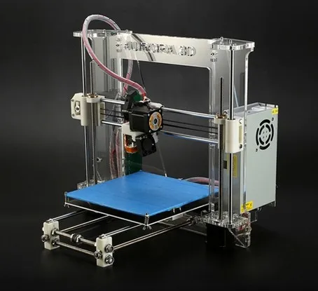 You can then add push pins or inserts. IPC recommends printing several inserts for thin models with protrusions that are at increased risk of breakage: in this case, they are easy to replace. Mold handling and assembly are operations that require care as 3D printed parts can break during processing. 3D printed molds should be placed in a metal die or master mold to withstand the pressure.
Form printed in Rigid 10K Resin and mounted in a metal matrix. Moving side with ejector pins (left) and fixed side (right).
Form printed in Rigid 10K Resin and mounted in a metal matrix. Movable side with ejector pins, inserts, SLS bezel (left) and fixed side (right).
Conditions of injection molding process
The team has cast thousands of models under the following injection molding conditions:
- Injection molding machine: industrial, ENGEL 150T
- Injection molding material: polypropylene (PP)
- Injection molding temperature: 200° C
- Casting pressure: 180 bar
- Mold clamping force: 125 kN
- Release agent: none
- Cooling system: none.
 The temperature was controlled by a thermal imaging camera and the cycle only started when the plate temperature was below 36°C.
 - Ejection: automatic with ejection pins and robotic arm designed to move the part
- Cycle time: 150 sec.
results
IPC cast 90 polypropylene models in a mono-material mold printed in High Temp Resin.
Cast models were distinguished by high surface quality and detail. However, after 31 iterations, the mold began to crack, which affected the surface quality of the remaining cast models.
Model #31 (left) and Model #90 (right) molded in High Temp Resin
1000 polypropylene models with a multi-material mold printed with Rigid 10K Resin.
Cast models were distinguished by high surface quality and detail. There were light fusions after the first castings and small cracks around the core clamps after 900 castings. Lightening appeared at the place where the sprue was supplied.
Light fusion on last model (left) and small cracks after 900 castings on Rigid 10K Resin core.
Textures on finished models molded in multiple materials.
IPC recommends selecting Rigid 10K Resin to maintain shape durability.
This polymer is less brittle and exhibits better load strength than
High Temp Resin. The 3D printed mold should be processed to improve parting line accuracy and reduce flashover. Using a multi-material soft-framed mold is a great alternative solution for compensating for dimensional variations. IPC suggests that the molding process will be more difficult when dealing with viscous materials such as polycarbonate (PC),
as well as casting temperatures above 240° C.
IPC evaluated the possibility of using 3D printed injection molds in low volumes. With a mold core printed in Formlabs Rigid 10K Resin and a soft frame printed in Nylon 12 (Polyamide 12), thousands of polypropylene parts have been cast, reducing printing costs by 80-90% compared to using a metal mold.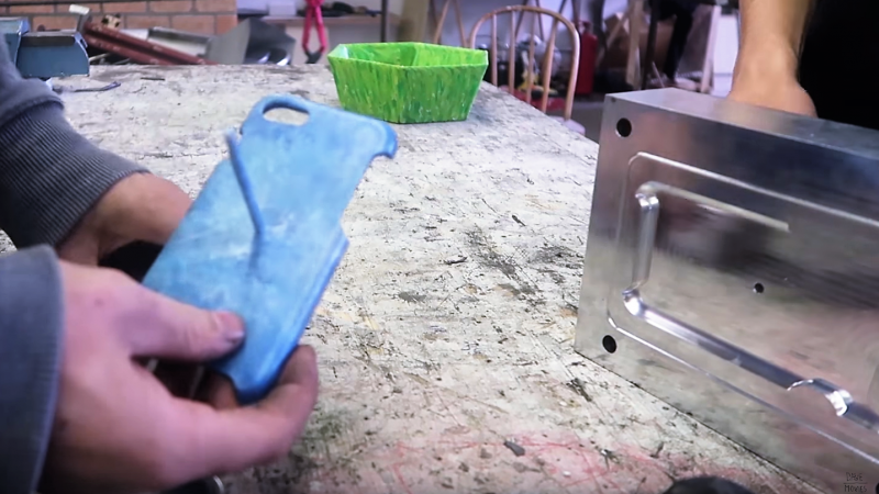
Desktop 3D printing is a powerful solution for making injection molds quickly and inexpensively. It requires a limited amount of equipment, which reduces the time of the CNC and skilled operators and frees them up for other important tasks. Desktop 3D printing is easy to integrate into any injection molding workflow as it is easy to install, operate and maintain. Manufacturers will benefit from the speed and flexibility of in-house 3D printing to create a mold and combine it with the power of industrial injection molding.
As a result, it will be possible to produce a series of products from conventional thermoplastics in a matter of days.
We will keep you updated with the latest news!
Your team iGo3D Russia :)
Our groups in social networks:
YouTube
VKontakte
Injection molding from 3D printed molds
Study of low-volume production of small plastic parts
SUMMARY
This white paper describes the production of small injection molded thermoplastic parts that were created using Form 2 3D printed molds and injection molding using a Galcom Model-B100 injection molding machine. Two transparent resin molds were tested: one large butterfly mold and one mold with four small butterflies in one block. A third mold for the USB stick case was tested in high temperature polymer. These molds were 3D printed by Formlabs and the castings were made by Galomb Inc and Formlabs in a variety of materials.
Formlabs and Galomb, Inc.
LOW-VOLUME 3D PRINTED PARTS
Most of the plastic products in the world today are made by injection molding. Using inexpensive desktop 3D printers and injection molding machines, molds can be created to produce small functional parts from manufacturing plastics.
For low volume production (approximately 10-100 parts), 3D printed molds save time and money. They also allow for a more flexible approach to manufacturing, giving engineers and designers the ability to easily modify molds and continue iterating their designs at low time and cost.
The Form 2 Stereolithographic 3D Printer (SLA) produces completely solid, smooth parts that can withstand the temperature and pressure of desktop injection molding.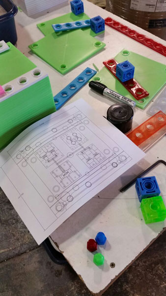 3D prints produced using SLA are chemically bonded so that they are completely dense and isotropic, producing functional shapes with a quality not possible with FDM.
Formlabs is partnering with Galomb Inc., a manufacturer of low cost injection molding machines, to test and demonstrate the viability of SLA injection mold printing.
Fig. 2 : 3D printed molds in aluminum frames.
METHOD
Both clear and high temperature resins can be used to print small functional forms, with high temperature resins offering compatibility with a wider temperature range of
thermoplastic melts. Formlabs Clear Resin was chosen for its strength, high detail and smooth surface Clear Resin is preferred for its transparency as you can easily see when forms are being filled, but any of the standard Formlabs Resins (clear, white, black and grey) can also be used as they have similar mechanical properties. The plates were printed with a layer height of 100 µm and took approximately 5 hours per plate. Depending on the geometry, multiple shapes can be printed at once on the build platform to improve printing efficiency.
Fig. 3 : Printing setup in PreForm with cavities up.
Two forms were printed from transparent resin. Parts and subsequent molds were designed to match Galomb machine vise sizes, 1 in3 injection cylinder capacity, and Form 2 build volume. supports were polished.
The parts were then cured for one hour under a 405 nm UV lamp to achieve full mechanical strength and rigidity. For a better understanding of the impact of post-curing on parts, see the Formlabs UV post-curing booklet.
Fig. 4 : 3D printed molds in aluminum frames and die-cast parts.
The first was a large Formlabs butterfly logo and the second was four small Formlabs butterfly logos. Both molds had a cavity, narrow inlets, and sprue at the point of injection and were designed in Solidworks. The molds were inserted into aluminum frames to provide protection from the downward pressure and heating of the injection nozzle. Aluminum frames can also prevent the shape from deforming after repeated use. The frames shown in figures 2 and 4 were custom made by Whittaker Engineering in Scotland, but standard aluminum frames are readily available on request from injection molding machine manufacturers.
Plastic pellets can be purchased online or from suppliers such as IASCO-TESCO. To create different colors, the molten plastic was pre-mixed with powdered dyes prior to injection.
Using a Model-B100 benchtop injection molding machine, Galomb tested printing plates with 25 shots of LDPE. LDPE melts at approximately 325°F (163°C) and was chosen for its low melting point. Of note, Formlabs Clear Resin has an HDT at 0.45 MPa 73.1 ºC after post-cure (see Material Data Sheet). HDT is a measure of the thermal properties of a material, but does not rule it out for use, although LDPE has a higher melt temperature. Whether your 3D printed mold will withstand the injection molding process depends on the melt temperature of the injection material, part geometry, and cooling and cycle times.
RESULTS FOR CLEAR POLYMER
After 25 injections of LDPE, there was no noticeable deterioration in the surface of the molds (chips, cracks or scratches). LDPE is not prone to sticking to polymer molds when tested, but other plastics may require the use of a mold remover to assist in part removal. Adhesion of the part to the mold can cause mold wear during ejection. Release agent is widely available, and silicone release agent is compatible with Formlabs standard and high temperature resins.
The cycle time for each injection was approximately three minutes. This process was accelerated by using compressed air to cool the mold. Cyclic injection into forms printed on the Form 2 causes the form to heat up. To counteract this, the cooling time between open mold cycles must be increased. While the mold cannot deform, too much residual heat will reduce molding success if the mold is opened too early. Galomb also improved molding success by etching shallow (0.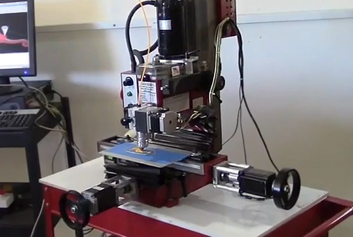 05 mm deep) vent holes (not shown) leading from cavity edge to mold edge so that air does not enter the cavity during injection.
Some of the injections showed a leak in the parting line due to deformation of the polymer mold during the cooling phase after several injections. Increasing the clamping force in the vise can help mitigate leakage, as can polishing the parting plane of the mold to make it as flat as possible. Galomb proposed incorporating channels into the mold design to include metal tubes and fill them with aluminum epoxy, as a strategy to strengthen the mold, reduce warping, and improve cooling time.
Fig. 5 : A range of injection molding parts made using 3D printed molds.
FURTHER TESTING WITH HIGH TEMPERATURE POLYMER
Clear resin molds have been successfully tested using LDPE, which has a relatively low melt temperature. Higher melt temperatures can cause thermal shock in clear resin printed parts, which manifests itself as a deformed mold surface.
Transparent resin molds experience thermal shock when exposed to higher temperature molten plastic.
Formlabs printed the shape of a USB device case in High Temp Resin to test
| Melting Point | plastic | High Temp Polymer (HDT at 0.45 MPa = 289° C) | Clear Polymer (HDT at 0.45 MPa = 73.1°C) | |
| LDPE | 163 °C | ||
| PP | 177 °C | ||
| TPE | 177 °C | ||
| PLA | 180 °C | ||
| ABS | 204 °C | ||
| HDPE | 204 °C | ||
| EVA | 204 °C | ||
| Polystyrene | 226 °C |
High temperature polymer molds showed no temperature degradation at the mold surface for any of the tested plastics.
*DURABLE RESIN polymer is under development and final specifications are subject to change.
High Temp and Standard are the polymers best suited for molding. Of the Formlabs resins, High Temp has the highest HDT at 0.45 MPa and low thermal expansion. It is also the stiffest material with the highest stretch factor.
The relatively high stiffness of High Temp Resin means that the mold will not deform when the part is removed. This makes the use of a release agent especially important for removing parts molded from rigid plastics such as polystyrene.
GENERAL TROUBLESHOOTING
Form overflow leak.
Leak occurs when the injected plastic is forced out between the two mold halves. This can happen when the shape is overflowing, or if the split plane is not completely flat. Adding thin exit ports to the mold can help mitigate leakage from overpressure within the mold, facilitate part removal, and eliminate entrapped air that can cause bubbles in the molded part.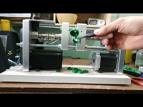 Although not shown, the plates were tested without the aluminum frame. The downside to this approach is that these parts use more material, which increases printing cost and time, and the forms can be more prone to warping. With this method, a steel washer placed between the printing plate and the nozzle of the injection molding machine protects the print from direct contact and helps distribute forces. In addition, pre-sealing the injection molding cylinder against a metal block helps ensure there are no air pockets to disrupt the plastic flow.
Printed lines visible on some parts; this can be reduced by printing the form with a lower layer height. The plates used in this study were printed at 100 µm, but 50 or 25 µm could also be used. This will improve the cleanliness of the plate surface, but increase print time and reduce tank life.
Final USB device case molded from high temperature resin.
DESIGN INSTRUCTIONS.
When designing a form, consider what will print successfully, as well as what will be successfully molded.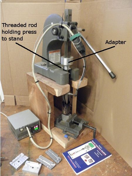
- Adding one to three degrees of recess on surfaces perpendicular to the direction of the recess will allow easier part removal and minimize mold degradation. Fillets should be applied to the inside edges to reduce buckling from internal plastic stress and facilitate removal of the part.
- Embossed and engraved parts must be offset from the surface by at least 1 mm.
- If you are planning on using an aluminum frame, The surfaces of the separation planes can be polished with fine sandpaper to reduce flare. add an extra 12mm thick plate to the back of the mold plate to account for compressive forces and ensure complete sealing.
- Be sure to orient the mold halves in the PreForm so that the cavity is facing up. This will prevent reference marks inside the cavity and make post-print processing easier.
90° angle
2° recess
Optimum condition 2° recess and rounding.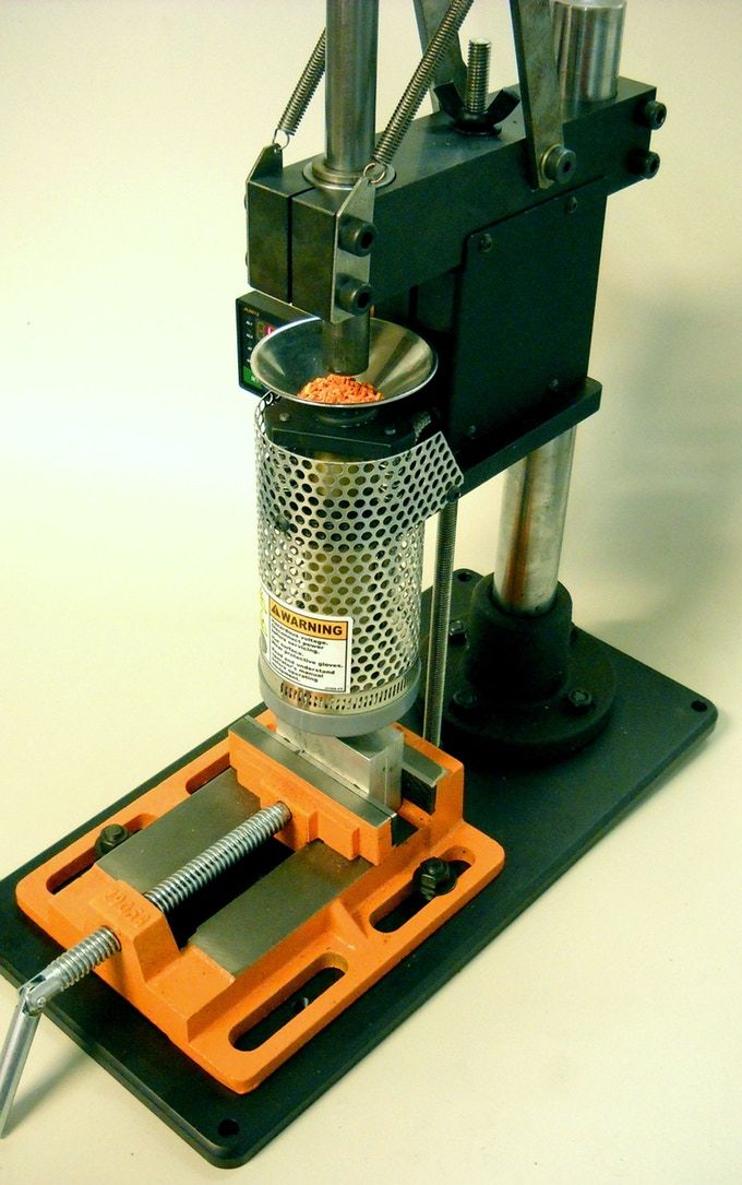
Learn more