Cubify 3d printer software
No Really, It's The End Of The Line For Cubify « Fabbaloo
By Kerry Stevenson on October 20th, 2019 in Corporate
Tags: 3D Systems, cartridges, cubify, materials, store
3D Systems’ CubePro 3D printer [Source: 3D Systems]
Cubify is really and truly shutting down at the end of the month.
Wait a second — Cubify? Wasn’t that line of desktop consumer-style 3D printers shut down by 3D Systems many years ago?
Yes, indeed. In December 2015, 3D Systems abruptly shut down their entire consumer 3D printing division, including hardware, software, 3D models, and services. The few remaining machines were sold off at that time.
Much time has now passed since that dramatic event, but during that period Cubify hasn’t exactly disappeared. 3D Systems continued to supply materials for the CubePro devices, which used proprietary cartridges. Without a hack, the only way these devices could be used would be to obtain stock of such cartridges.
As large numbers of CubePros were sold to schools, there was a small ongoing market for cartridges. Thus 3D Systems continued to sell them both from an online store and from their Amazon page.
However, today I stumbled on their online store page (please don’t ask why), and saw this ominous notice:
“The storefront on 3dsystems.com closed on September 13th, 2019. If you have a warranty claim or a question about an open order please visit our support site and open a ticket.
A limited quantity of CubePro material cartridges will be available for purchase on our Amazon store until November 1st, 2019.”
Aha! It seems that 3D Systems is finally and officially closing sales of CubePro materials at the end of this month, after four years of extended service.
Their Amazon page shows some 14 different cartridge types for sale, although “quantities are limited”. These are priced at US$99 each, for cartridges containing around 600g of filament material. With proprietary material costing in excess of US$150/kg, it’s not surprising the CubePro systems were not particularly successful, as many competitors offered equipment with far lower material costs.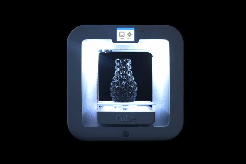
It seems, however, that 3D Systems will leave one small bit of support left: the ability to download manuals and a method of activating machines, which was a step required before you could operate these 3D printers.
For those somehow still using the now-ancient CubePro systems, it’s long past time to move on to other equipment.
While 3D Systems no longer offers this style of desktop equipment, the good news is that there are plenty of incredibly powerful desktop 3D printers now available at very low cost that can easily match or beat the performance of the defunct CubePro.
Via 3D Systems Cubify Support and Amazon
TwitterKerry Stevenson, aka "General Fabb" has written over 8,000 stories on 3D printing at Fabbaloo since he launched the venture in 2007, with an intention to promote and grow the incredible technology of 3D printing across the world. So far, it seems to be working!
View all of Kerry Stevenson's posts.
Thoughts on Cubify Printers & Software - 3D Printing - Talk Manufacturing
pattersonc
#1
I’m new to 3D printing world here and am learning as I go.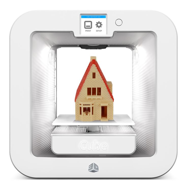 I’ve been using Cubify’s Design software and researching their printers. I thought I read somewhere where there is also open source 3D printing software. So my two questions are:
- Is there open source 3D design software? If so, who maintains it and is it decent?
- What are your thoughts on Cubify’s 3D printer the “Cube Pro” ? As I’ve been seeing people with printing hubs I haven’t seen many of Cubify’s printers showing up in the results.
Thanks in advance for your thoughts
ianRmoore
#2
1st question: For parametric modeling I have started to use Onshape although many people use Sketchup. For modeling/artistic stuff many people use Blender. Being able to save a .stl file is usually the key.
2nd question: 3D Systems has had delivery issues in the past and generally it is said their hardware is not open source or easy to work on.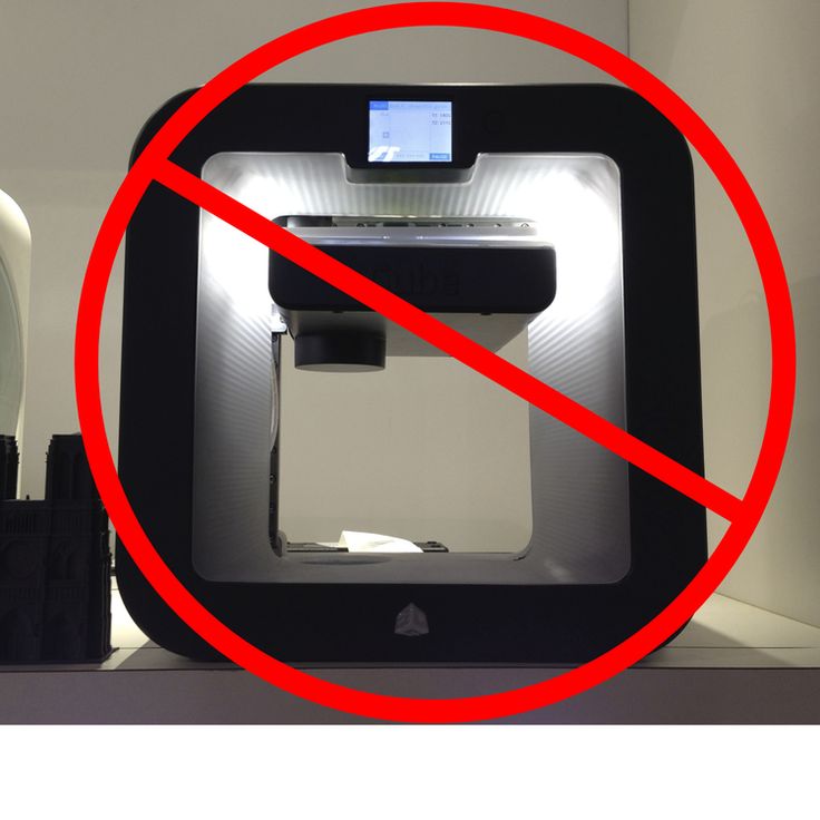 Primarily, their filament cartridges are expensive. I used one in college about 2 years back and the print quality was comparable to the makerbot at the time. About a year ago I tried ordering a Cube and after about two months of waiting I had to cancel my order and just go with a different supplier. Maybe 3D system’s customer service is better for institutions or high-grade professional customers but I didn’t get a warm fuzzy feeling with them.
1 Like
pattersonc
#3
Thanks for the reply and info.
You mention Onshape and Sketchup… are those the best open source alternatives in your opinion?
PeterMake
#4
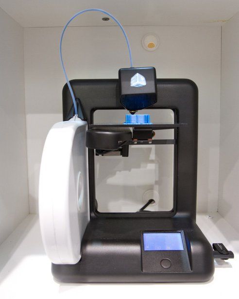
I have among my other 5 3D printers Cube 3.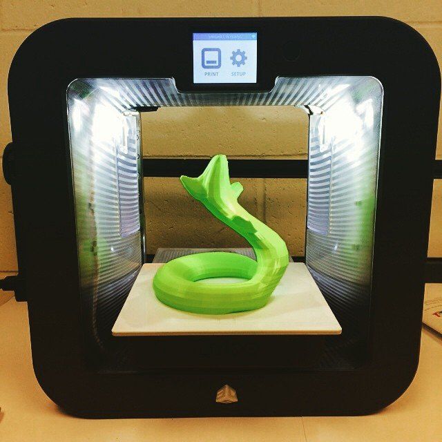
It is very easy to use, prints great when it works, but it is closed system just as the Cube Pro.
This means you have to use 3D Systems Filaments and Slicer.
3D Systems use to have issues with late deliveries but not any longer at least I never had a problem with shipping nor their customer service. I think both maybe were not up to par in the past but they have improved both.
I would have to ask you what you plan on printing with the printer?
I myself would not get a Cube Pro as I think there are better printers on the market within that price range.
As far as Cubify’s Design Software I think it’s pretty good. I have other software’s such as Sketchup, Auto Desk Fusion 360, Solidworks, etc. and I use the one that will be the most simple to use for the part I am designing. With that said I use Cubify’s Design the most as it is easy to use and not much of a learning curve.
One more thing, Cubify also has Cubify Invent, it is exactly like Cubify Design but you cannot do assembles.
However it is $49.00 for Cubify Invent verses $199.00 for Cubify Design.
I not ever use assemble so I should have gone with Invent and saved.
For the money you cannot go wrong with Cubify Invent or Design.
1 Like
pattersonc
#5
Peter,
Thanks for your reply and the info. Very helpful!
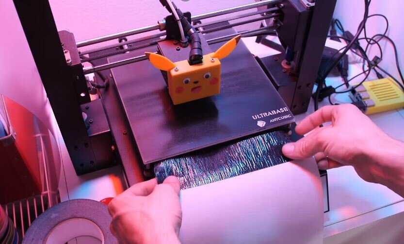
How to tame a Cubify Cube 2 3D printer / Sudo Null IT News
But there are 2 significant disadvantages.
The first drawback is that proprietary software does not allow you to change print settings at all. In general, it turns out that the printer will almost certainly print what is needed, but after several figures are printed, there is an irresistible desire to change something in the settings and it turns out that nothing can be changed in principle. Even the thickness of the layer. It turns out a 3D printer for housewives and schoolchildren.
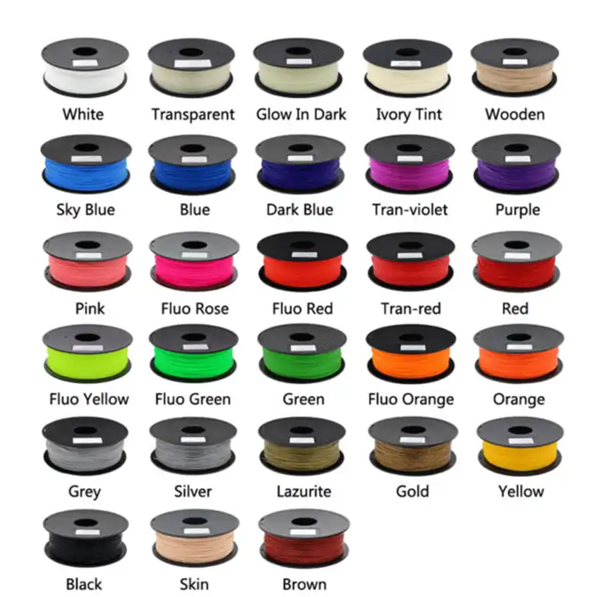
The second drawback is the proprietary chip cartridge with plastic. The plastic in it is about 300 grams, and it costs as much as a few kilograms of usual. In addition, cartridges still need to be looked for.
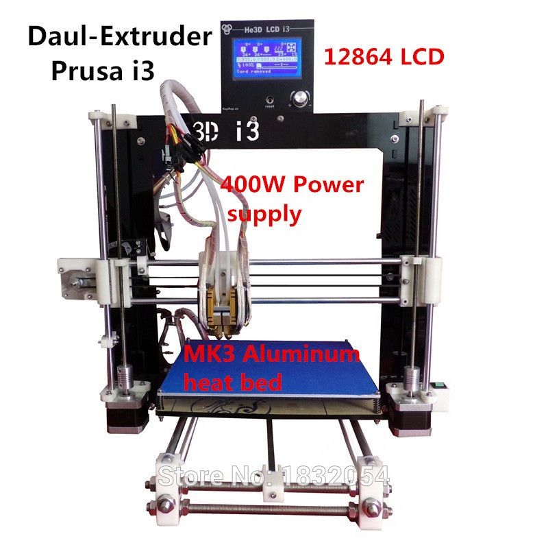
In general, without hesitation, I decided to replace the control electronics with a much more interesting one, in the form of an Arduino mega 2560 + Marlin firmware.
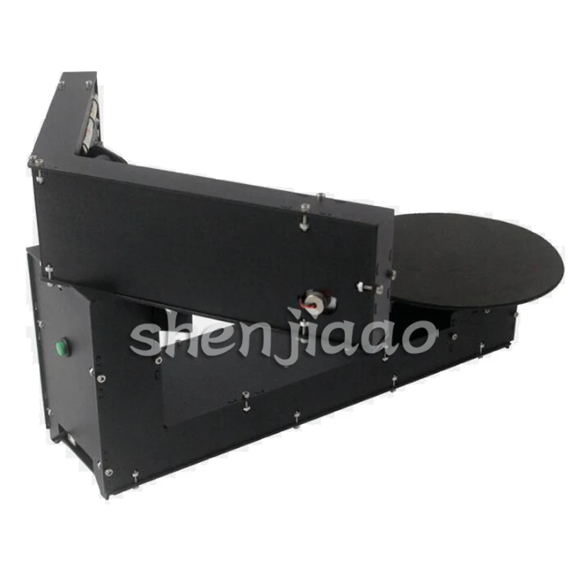
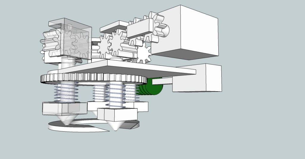
After disassembling the printer, the following board appeared to my eyes:
In the photo, the board with the native control controller already soldered out (it can be seen on the right side of the board with adhesive tape attached so as not to get lost). There are also trace signatures needed to connect the stepper motor drivers to the microcontroller.
Power circuits
The printer is powered by an external 24V power supply. This voltage is directly used by the power part of the stepper motor drivers, the extruder heating driver, and to power the fans. To power the logic part, this voltage is first reduced to 6V by a linear voltage regulator, after which it is fed to a 3.3V regulator - this voltage is used to power the MK, the logic part of the stepper motor drivers, the WiFi module and the built-in microSD memory card. Also, 6V is converted by a low-power regulator into a voltage of 5V, which is used to power an external USB flash drive
Control microcontroller
Everything is controlled by a PIC microcontroller, to which peripherals are connected, represented by stepper motor drivers, a WiFi module, a flash SD card, external USB ports and a touch graphic LCD display. I could not find documentation for this display, and it was lazy to disassemble its interface with a data logger. In general, I gave up all this luxury by desoldering the MK and cutting the power path to SD and WiFi.
Stepper motor drivers
There are 4 identical A3979 drivers installed on the board. Each driver receives 3 control signals #ENABLE, STEP and DIR. The microstepping mode with 16 cycles per step, which is the maximum available for this microcircuit, has been selected. The output current given by the REF pin voltage is also fixed.
How I almost burned the motors
to an increase in voltage at the output of the divider. Because of this, after the alteration, the current supplied to the motors increased greatly, but during the setup I did not notice this because I did not turn on the motors for a long time. And I noticed this jamb only when I had already calibrated everything, assembled and launched the first long-term print. I printed a cube. Print time was over half an hour. And already at the end of printing, I felt the smell of burnt windings of stepper motors, which is not typical for printers. When trying to check the temperature, the SD almost got burned. The temperature was much more than 100 degrees. But it passed - the motors were not damaged. Therefore, I had to disassemble the printer again and change the resistance to reduce the current.
Heating element driver
There are 2 VN5050 chips on the board. This is a single channel load driver with output current up to 16.5A and current feedback. One of the microcircuits is connected to the extruder heater, and the second one controls the fans for blowing the model. Although, given the capabilities of this microcircuit, the second driver can be used without damage to switch the heating table (manufacturers most likely counted on this because a conventional logic level field effect transistor can also be used for a fan).
This chip is turned on by supplying a logical unit to the Isense input, no matter how paradoxical it may sound.
Fan control
In addition to fans for blowing the model, there are 2 more: cooling the board and blowing the extruder. They are controlled in the most clumsy way "on-off" through field-effect transistors.
Others
There is also a WiFi module and a microSD memory card on the board, but I turned off the power from them by cutting the track as these devices are unnecessary.
Modernization
From the very beginning, I set myself the goal of converting the printer with the lowest cost of purchasing components and materials, and the native board suited this very well. In fact, all that was required for the conversion was the Arduino mega 2560 board, a few resistors and a lot of thin wires.
When compiling the firmware, I indicated that I was using the RAMPS 1.4 shield with one extruder, so I plugged all the wires into the arduino, looking into the circuit.
First of all, the control controller and the 3.3V stabilizer were soldered. After that, I, referring to the datasheets of the drivers, found and signed all the tracks responsible for controlling the peripherals. Also called the limit switches. It turned out that almost all inputs and outputs were usable with 5V logic.
The only thing that had to be redone was the thermistor connection. The thermistor is connected at one end to the common bus, and the second contact is connected to the 5V bus with a 4. 7 kΩ resistor. The analog signal is taken from the second output of the thermistor and fed to the input of the controller A13.
The resistors that set the reference voltage in the stepper motor drivers have also been replaced. The fans for blowing the extruder and the board must be constantly turned on, so 5V was applied to the gates of the corresponding transistors. Drivers for controlling the heater and blowing fans of the model connected to the outputs D8 and D9.
Finished the arduino board a little. Soldered the power connector and USB. Also, in order for the controller to be powered exclusively from the printer and not turn on when the USB cable is plugged in and the printer is not powered, I soldered the output from the transistor:
Powered the controller by applying 6V voltage from the printer board to the Arduino Vin pin. To power the logical part of the stepper motor drivers, 5V was applied to the line, along which the 3.3V voltage from the arduino used to go. I connected the zero points of the arduino and the main board with one thick wire to avoid the formation of closed loops.
The connector installed on the board was used for the USB connection. During the first test, the printer often fell off the computer. This was most likely due to the tracks that used to carry the D+ and D- signals on the PCB, which were hanging in the air. I cut them right next to the connector and twisted the D + and D- wires together, going to the arduino board. After that, the connection was no longer interrupted.
As a result, this is what happened:
It's time to configure the firmware and software.
I used Marlin firmware. There is a lot of information on its configuration on the Internet, and I have repeatedly come across its configuration for different printers, but this time the situation was somewhat atypical. The thing is that the limit switch along the Z axis is installed at the bottom, that is, in the maximum position.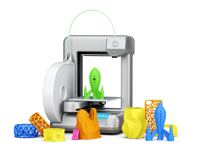 Thus, when parking, the Z-axis becomes the maximum position. I conjured with the settings in the firmware for quite some time, until I knew Zen. But first things first.
#define ENDSTOPPULLUPS // enable pull-up resistors on limit switch inputs
const bool X_MIN_ENDSTOP_INVERTING = true;
const bool Y_MIN_ENDSTOP_INVERTING = true
const bool Z_MIN_ENDSTOP_INVERTING = true;
const bool X_MAX_ENDSTOP_INVERTING = true;
const bool Y_MAX_ENDSTOP_INVERTING = true;
const bool Z_MAX_ENDSTOP_INVERTING = true; // inversion of limit switches inputs
#define DISABLE_X false
#define DISABLE_Y false
#define DISABLE_Z false
#define DISABLE_E false // don't disable unused motors
#define INVERT_X_DIR true
#define INVERT_Y_DIR false
#define INVERT_Z_DIR true
#define INVERT_E0_DIR false // setting the correct direction of movement of the motors
#define X_HOME_DIR -1
#define Y_HOME_DIR -1
#define Z_HOME_DIR 1 // on the Z axis, the limit switch is at the maximum position
#define X_MIN_POS 0
#define Y_MIN_POS 0
#define Z_MIN_POS 0
#define X_MAX_POS 140
#define Y_MAX_POS 140
#define Z_MAX_POS 140 // minimum and maximum coordinates along the axes
#define HOMING_FEEDRATE {50*60, 50*60, 40*60, 0} // parking speeds
#define DEFAULT_AXIS_STEPS_PER_UNIT {80,80,80,115.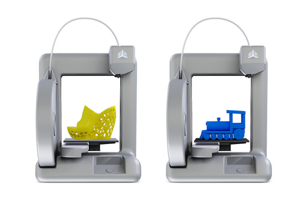 75} // number of steps per mm
#define DEFAULT_MAX_FEEDRATE {300, 300, 300, 20} // maximum speed
#define DEFAULT_MAX_ACCELERATION {1000,1000,100,10000} // maximum acceleration
Next, I configured the Repetier Host to work correctly with the printer. The settings are located in the "Configuration" tab, "Printer settings" item.
In the "Connection" tab, I selected the desired port and its speed.
In the “Printer” tab, I changed the speed of movement along the Z axis to 1500 mm / min, and changed the value of the parking position along the Z axis from 0 to 140 - it is with this value that you need to accurately calibrate the zero position if necessary before starting printing.
In the "Extruder" tab, I specified the nozzle diameter as 0.3 mm.
In the "Dimensions" tab, I specified the dimensions of the printable area. For this printer, it turns out exactly 140 mm in all axes.
After that, the printer worked fine even without tweaking the slicer. Slic3r in easy mode. True, the speed is not cosmic.
At the moment, in my free time, I'm figuring out how to fine-tune the slicer to get the best speed quality.
Thank you for your attention.
3D Printing Software
Basically there are 4 steps to go from concept to printed physical object:
- 1. The idea itself,
- 2. Its digital model,
- 3. A set of print head paths,
- 4. And finally, printing.
Turning an idea into a physical object is carried out using three levels of software:
In 3D printing, CAD and CAM (Computer Aided Design/Manufacturing) programs are used to create digital models and their translation into physical instructions for the printer; while the “client” program manages the printer hardware.
Modeling / CAD
Even if you are scanning a real object with a scanner, you will most likely want to refine it with CAD programs. There are many file formats for models, but most 3D printers use the STL format. Unfortunately, not all STL files can be printed. A model suitable for printing should have a "sealed" form with a closed monolithic surface, without any breaks, that clearly separates the inside and outside of the model. Computer graphics programs (such as Blender) usually model the surface without caring about the "tightness" of the model. Therefore, beginners are advised to use software that is more specialized in creating monolithic models, for example, 123 Design, at first.
Sketchup
TRIMBLE
20000
0/$ 590 (PRO)
FreeCAD
Juergen Riegel, Werner Mayer
Sculpting software designed specifically for 3D printing. Supports import and export of STL format files. Supported OS: Windows
C AM/ Slicing software.
"Slicing" (separation of the model into layers for 3D printing). A slicing program translates 3D models into physical instructions for a 3D printer. They are a sequence of paths that the printer's print head will take to fill (print) the shape of an object. The most common format for such files in 3D printing is G-code.
Printer management (“ Client” program)
The “Client” program is basically a kind of printer control panel. It sends instructions to the CAM printer and provides an interface for controlling printer functions. Currently, there is a tendency to combine CAM and client programs into a single printer management interface.
| Replicator G | MakerBot | 2008 | Free | Original Replicator printer client, later replaced by MakerWare. |