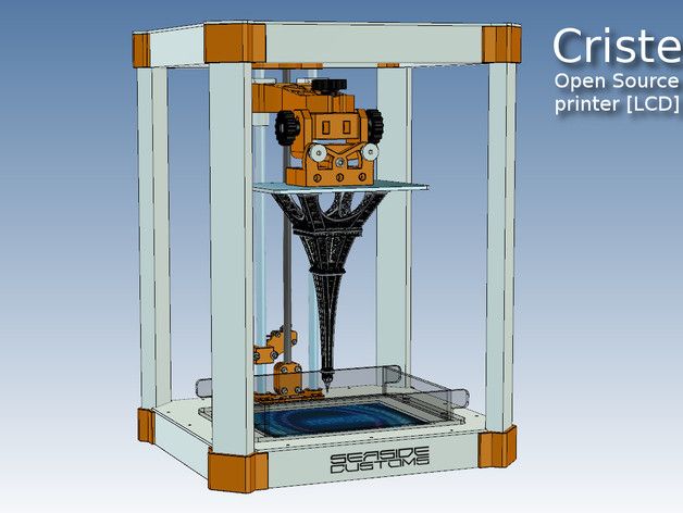
Clean build plate 3d printer
the correct way! – 3D Solved
It happened to me when I got started in 3D printing, so it may as well be happening to you. You think you found those golden settings on your slicer that just output nice-looking prints and you get the feeling that you may be a printing genius.
Perhaps, you think, you should buy twenty more printers and start your own printing farm. In your mind, you are already thinking about the size of your future yacht and its amenities.
Suddenly, your objects detach from the build plate in mid-print. It may be time for a new series of tutorials before we can go back to our 3D printing empire.
If what happened above is word for word what happened to you, it may be time to learn how to keep a clean printer bed (and lower your overall expectations).
A clean printing bed is especially important for improving layer adhesion to the build plate and yields a better looking first layer. Isopropyl Alcohol (IPA) in graduations ranging from 70% up to 99. 99% is appropriate for this task.
Soak the IPA in paper towels, microfiber cloth, or cotton and clean the bed surface in a circular motion. Rinse and repeat until the build plate is free of leftover filament, fingerprints, oils, and other imperfections that affect printing quality. Depending on the build plate type, you can also use acetone, but only use it as a last resort and on the specific parts where you could not clean it using alcohol.
If you do not know if your build plate is dirty or clean, assume that it needs some cleaning. It never hurts!
Look at the picture below. If your surface looks like the left-hand side, you clearly do not suffer from dirty-build-plate syndrome (or DBPS). On the other hand, if you identify with the right side of the picture, it does not take a germaphobe (nor a tutorial) to infer that some cleaning may be necessary.
Source: Prusa Knowledge BaseTable Of Contents
- Why is 3D Printer Bed Cleaning Important?
- Advantages of a Clean 3D Printer Bed
- Maintaining Your 3D Printing Bed
- Polyetherimide (PEI) Printing Beds
- Glass
- Adhesive Tape
- Conclusion
Why is 3D Printer Bed Cleaning Important?
The 3D printer bed serves as the base on which your model is printed on.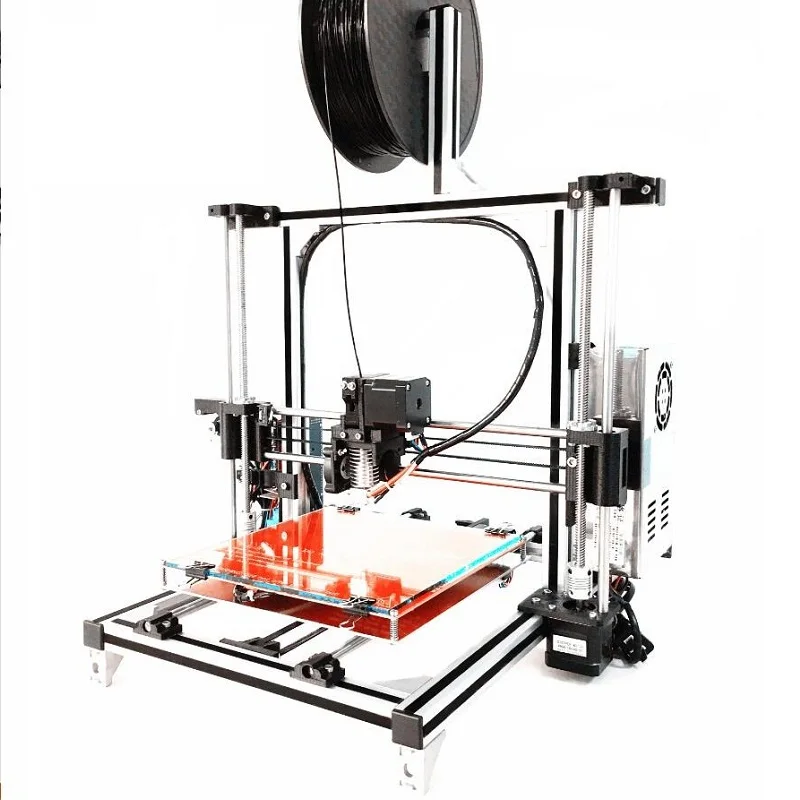 The printing process can leave residual filament after the process is completed.
The bed also becomes dirty by general handling (skin oil, fingerprints, dirt, etc.) and materials from its surroundings. These contaminants affect the quality of your future prints and damage the printing bed over time.
Skipping maintenance can ultimately cause irreversible damage that can only be resolved by replacing the printing bed.
Advantages of a Clean 3D Printer Bed
Having a clean 3D printer bed is essential for achieving perfect results. Unclean beds have recurring issues with layer adhesion that compromise the quality of your prints.
Keeping the 3D printing bed in an acceptable state prolongs its serviceable life and can save you from spending a few extra bucks on somewhat expensive replacements.
A key issue with printing is the quality of the first layer and its adhesion to the build plate.
A clean 3D printer bed ensures your models print properly without any issues.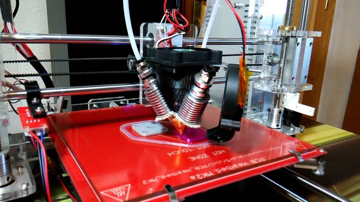 Remember to follow the recommended care for your printing bed as it varies according to models and their materials.
Maintaining Your 3D Printing Bed
Most printer beds are made of glass Polyetherimide (also known as PEI) or covered in tape. At 3DSolved we leave (almost) no rock unturned, so we will cover those types!
Polyetherimide (PEI) Printing Beds
PEI sheets are being actively used as 3D printer bedding since they require little maintenance and are suitable for the process. They are also resistant to wear under extreme temperature and radiation that are a regular feature in 3D printing.
PEI sheets have good bed adhesion and don’t normally get stuck with the model if maintained properly. Consequently, there are few instances where adhesives and tapes are needed when using them.
However, PEI sheets do need maintenance to keep up the quality of their prints. Their adhesion becomes weaker over time as the bed is repeatedly subjected to printing radiation, temperatures, 3D printing inks, environmental contaminants, and general handling.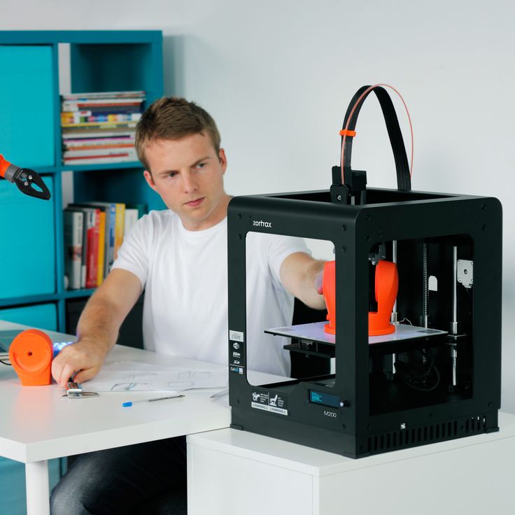
This leaves glue, printing ink, and filaments as well as oils and dirt on the surface. Simple cleaning procedures such as scratching, scraping, and wiping with any cleaner can damage the bed.
How to clean a PEI Printing Bed
The following is the recommended way to clean a PEI 3D printing bed:
What You NeedYou will need the following materials for cleaning the PEI 3D printing bed:
- Isopropyl Alcohol (IPA) at 70% to 99.99% concentration (depends on cleaning)
- Acetone/Propanone
- Paper towels, microfiber cloth, or cotton
- Sandpaper (+1,500 grit)
Using unscented IPA at ~70% concentration is a safe standard to clean PEI 3D printing beds. It is volatile (it evaporates), which means you don’t have to worry about a liquid mess. Higher purity of IPA can be used in cases where oils, dirt, and grease have been layered considerably.
As a safety precaution, be sure to always use it in a well-ventilated area.
Let the 3D printing bed cool down before starting maintenance. Apply IPA and wipe it well with a dry microfiber cloth, paper towel, or cotton. The higher concentration of IPA completely breaks down organic oils and makes them easier to remove.
Use acetone for removing 3D ink and plastics that are stubbornly bonded with the bed. Pour the acetone on the cloth (not directly on the bed) to dampen it.
While PEI is not soluble in acetone, pouring too much on one area for prolonged periods can still damage it. Wipe the bed in circular strokes to remove the plastic compounds. You may pour some of it directly on tough stains to soften them for removal.
Remember to use acetone only when alcohol is no longer completely cleaning the surface.
In case of very stubborn stains or uneven surface, use fine-grit sandpaper (+1,500 grit) to scrub off the buildup or simply smoothen the surface for even traction after cleaning it. Remember to clean again as sandpapering produces very fine dust from grinding the surface.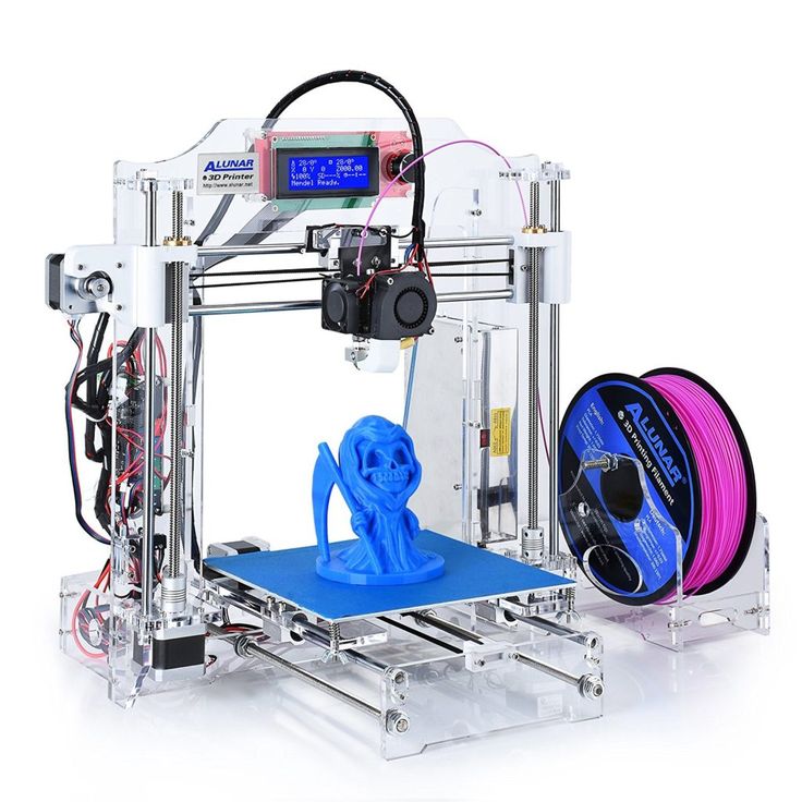
The time between maintenance is variable for different brands of PEI sheets and how often they are used. It also decides their serviceable life. Using glue and hair spray has also become a common hack to prevent the model from sticking to the bed. While the technique has proven effective, cleaning up can become problematic without proper guidelines.
To avoid damage, follow the instructions, though wiping is a standard after a few prints. Depending on the usage (a month on average), you may have to use acetone and sandpaper for restoration.
Glass
Glass is a very common material for 3D printing. It has a longer serviceable life than PEI. It also facilitates the usage of hairspray and adhesives for the 3D printing process because the surface does not react with any material. Glass 3D printing beds have an even surface that is also relatively easy to clean.
Glass by itself does not have a good surface adhesion.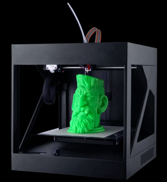 It is normally used with adhesives such as glue sticks and hairsprays. They increase surface adhesion for the first layer of print that sets a stable base for the rest of the model.
Cleaning Glass 3D Printing Beds
The following is the recommended way to clean a glass 3D printing bed:
What You Need- Scraper
- Dishwashing soap
- Sponge
- Isopropyl Alcohol (IPA) at 70% to 99.99% concentration (depends on cleaning)
- Paper towels, microfiber cloth, or cotton
Working with a heated glass 3D printing bed is easy as the surface does not become sensitive after getting warm. The heat makes the residual materials easier to scrape off. Be careful when scraping as glass is prone to scratches from sharp objects.
For starters, you should remove any traces of glue and hairspray on your glass 3D printing bed. This can easily be done with smooth, leveled objects such as a plastic ruler or metal spatula. Apply only the necessary force when using metal as it can scratch the glass. After removing glue, you can move on to removing the printing material stuck from the bed.
The blade on a scraper is extremely sharp. Exert a downward force with one hand and get a good grip at the edge or in the middle of the glass bed with the other. This will help remove the leftover material properly and prevent your hand from slipping. Remember that you will have to clean the bed later when you touch it with your hands, as it will leave residual oils and dirt.
Soap and water are perfect for removing glue and hairspray. Check the composition of your product to find out its solubility in water. In some cases, acetone and alcohol are better solvents for removing them. Wipe with disposable paper cloths or cotton because cleaning a microfiber cloth is difficult once used for this purpose.
Note: Be careful when using liquids because they can damage the nearby electronic equipment.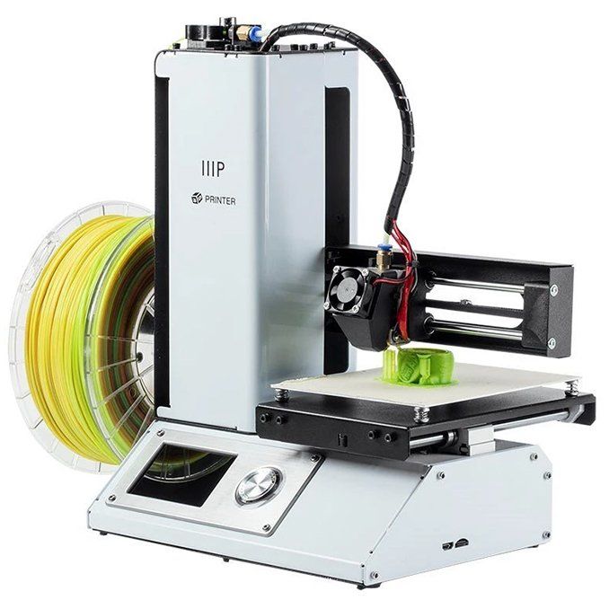
The time between maintenance of your 3D printing bed will vary depending on the usage and materials used to print the models. Scraping after every print removes any printing material stuck to the bed and prevents buildup which becomes harder to clean. It also keeps the next model’s base clean and easy to detach.
Use soap and water every week if the bed is being used every day. Otherwise, monthly maintenance is good enough to keep the prints well adhered. Use IPA and acetone only when the buildup has become very tough to remove.
Adhesive Tape
Adhesive tape is easy to use and cheap to replace. This makes it a reliable choice for anyone getting into 3D printing or looking for a cheap yet reliable 3D printing bed. It is mostly used with non-heated beds because it is sensitive to heat. Masking and painter’s tape are among the top choices for making an adhesive tape 3D printing bed.
Cleaning Adhesive Tape 3D Printing Bed
The following is the recommended way to clean an adhesive tape 3D printing bed:
What You Need- More tape of the same kind
- Scraper, plastic ruler, or metal spatula
- Isopropyl Alcohol (IPA) at 70% to 99.
 99% concentration (depends on cleaning)
 - Dishwashing soap
- Sponge
- Paper towels, microfiber cloth, or cotton
While adhesive tape is easy to use, it is equally hard to clean up. Scraping with a metal spatula is good enough to clean residual filament. Patch any area that is showing signs of wear. Be careful to maintain the level of your 3D printing bed (link to Ender 3 bed leveling guide) to ensure the model is printed without defects.
At times your bed will either be simply too used or will not have an even level. This is an indication to replace it. Remove all of the tapes and clean the base of the bed with IPA or soap and water. Let it dry completely, and then apply a fresh layer.
Time for MaintenanceAdhesive tape 3D printing beds have a short lifespan and need to be repaired and replaced often. Lightly scrape the surface after every print and replace the entire tape after a week or biweekly basis, depending on the frequency of usage.
Conclusion
By now, you should have no excuse for having a dirty printing bed on your machine. I should mention that I am not the most methodic person in the 3D printing world, so I tend to clean it when I start to see a higher failure rate. In short, my strategy can be described as reactive instead of preemptive.
If you do not want to get frustrated from time to time, waste filament, and get poor quality prints, you should always thrive to do preemptive maintenance to your 3D printer, and a clean printing surface is certainly not the exception!
We created a recommended products section that will allow you to remove the guesswork and reduce the time spent researching what printer, filament, or upgrades to get, since we know that this can be a very daunting task and which generally leads to a lot of confusion.
We have selected just a handful of 3D printers that we consider to be good for beginners as well as intermediates, and even experts, making the decision easier, and the filaments, as well as the upgrades listed, were all tested by us and carefully selected, so you know that whichever one you choose will work as intended.
How to Clean a Glass 3D Printer Bed – Ender 3 & More – 3D Printerly
Cleaning a 3D printer surface seems like such a simple task but it can be a little tougher than it seems. I’ve had trouble cleaning glass surfaces myself and searched high and low for the best solutions to do it properly, which I’ll be sharing in this post.
How do you clean a glass 3D printer bed? The best way to clean a glass bed is to slightly heat it then apply a cleaning solution, whether it be warm soapy water, window cleaner or acetone to your printer bed, leave it to work for a minute then cleaning with a paper towel or scraping it with a tool. A second wipe down is a good measure to take.
A common occurrence with 3D printer beds is having filament residue left over after removing a print. The worst part about it is how thin and strongly stuck down this residue is, making it very difficult to remove.
You should remove it because it can affect the quality of future prints. Residue can mix up with new filament preventing adhesion in places, thus potentially ruining your next print.
So keep reading for some great solutions to cleaning your 3D printer bed whether it’s adhesive residue or material left over from a previous print.
If you are interested in seeing some of the best tools and accessories for your 3D printers, you can find them easily by clicking here (Amazon).
How to Clean Your Ender 3 Bed
The simplest method of cleaning your Ender 3 bed is to use a scraper of some sort to remove the residue from a previous print or from an adhesive that you have used.
This usually works by itself with enough force, but definitely be careful where you put your hands because you don’t want to accidentally push the scraper into your fingers!
A good practice is to use one hand on the scraper handle and the other hand pushing down in the middle of the scraper to apply more force downwards.
With enough force and technique most beds can be cleaned to a good standard. Most 3D printers come with a scraper so this is a convenient fix.
One of the better scrapers out there is the Reptor Print Removal Kit which comes with a premium knife and spatula set. These tools slide comfortably underneath prints so your bed surface is protected and works well with all sizes.
It has a smooth ergonomic grip and it made of hardened stainless steel to do the job every time.
You want to remember to avoid using massive amounts of pressure and force on your printer’s bed because over time it can lead to unnecessary damage and scratches on the surface.
If this manual scraper method isn’t enough, you want to figure out the best cleaning solution for what material or residue is left over.
Some cleaning solutions work pretty well against most materials such as Isopropyl Alcohol (Amazon) which is 75% alcohol or Sterile Alcohol Prep Pads with 70% alcohol.
A lot of 3D printer users have gone for the sponge and warm water with soap method and this works pretty well for them. I’ve tried it a few times and I can say it’s a good solution.
You don’t want your sponge to be dripping because there are many electrical parts which can be damaged like the heating unit or the power supply.
Get some of the soapy water mix and gently rub it on the residue with your sponge or a paper towel until it softens and is removed. It can take some effort to get it to work.
This problem usually arises when residue is left overtime and builds up, some printers can be worse than others. A good practice when removing residue is to heat your bed up so the material is in it’s softened form.
It will allow you to clean off the residue a lot easier than it being hardened and cold which is why warm water works so well.
So to summarize:
- Use a Scraper and some force to remove residue
- Apply a cleaning solution of warm soapy water, isopropyl alcohol, window cleaner or other
- Let it sit and work to breakdown the material
- Use the scraper again and it should work just fine
Getting Rid of Glue on a Glass Bed/Build Plate
Many 3D printer users use 3D Printer Original Adhesive and apply a thin layer of this to their print bed to help objects stick to the bed and reduce warping.
People simply apply some glue to the general area where their print will be layered down. After the print is finished, you’ll find that there is glue residue on the glass or printing surface which has to be cleaned before starting another print.
It’s a good idea to remove the glass plate for thorough cleaning and use a reputable glass cleaning solution or window cleaner to get through the residue.
Rather than just using water, these cleaning solutions actually break down and tackle the residue, allowing for easy and simple cleaning.
- The first step is making sure your hands are washed, clean and dry before getting started.

- Now you want to simply use a dry cloth or normal paper towels to wipe down the glass.
- Take one paper towel sheet and fold it twice into a thicker, smaller square.
- Apply your cleaning solution directly on the glass bed, a few sprays should be enough (2-3 sprays).
- Let the solution sit on the glass bed for a minute to let it work and slowly break down the residue.
- Now take your folded paper towel and wipe the surface of the glass thoroughly, with medium pressure so all the residue is removed from the surface.
- After the first wipe down, you can add a few more sprays and a second wipe down to properly clean the surface.
- Remember to wipe down all around the surface including the edges.
Once you’ve properly cleaned your surface, there should be a clean, shiny surface with no residue left over.
Use your hands to feel over the glass bed to make sure it’s clear.
Now you just want to make sure your 3D printer bed surface is clean and level before placing the glass bed back onto your printer.
Cleaning PLA off a Glass Bed
PLA has got to be the most popular material used in 3D printing, which I can definitely agree with myself. The methods I’ve described above should do a great job cleaning PLA off a glass bed. This won’t be much different to the information above.
If the piece stuck down on your glass bed is the same color as your next print, some people will just print over it and remove it with the next object in one go.
This can work if your first layer adhesion isn’t too negatively affected so the print can form a solid foundation and actually finish.
My usual solution for cleaning the glass bed on my printer is a glass scraper (basically just a razor blade with a handle on it):
Cleaning ABS off a Glass Bed
ABS can be cleaned quite well by using acetone because it does a good job breaking down and dissolving it. Once you’ve applied acetone to your bed, leave it for a minute then wipe the residue off with a paper towel or clean cloth. You shouldn’t need to heat up your bed or use much force here.
If you aren’t already using a glass printer bed check out the links below and the reviews as to why they are so good. They do the job you need it to do with ease, at a competitive price and gives a lovely finish on the bottom of your prints.
Borosilicate glass for the following printers (Amazon links):
- Creality CR-10, CR-10S, CRX, Ultimaker S3, Tevo Tornado – 310 x 310 x 3mm (thickness)
- Creality Ender 3/X,Ender 3 Pro, Ender 5, CR- 20, CR-20 Pro, Geeetech A10 – 235 x 235 x 4mm
- Monoprice Select Mini V1, V2 – 130 x 160 x 3mm
- Prusa i3 MK2, MK3, Anet A8 – 220 x 220 x 4mm
- Monoprice Mini Delta – 120mm round x 3mm
If you love great quality 3D prints, you’ll love the AMX3d Pro Grade 3D Printer Tool Kit from Amazon. It is a staple set of 3D printing tools that gives you everything you need to remove, clean & finish your 3D prints.
It gives you the ability to:
- Easily clean your 3D prints – 25-piece kit with 13 knife blades and 3 handles, long tweezers, needle nose pliers, and glue stick.

- Simply remove 3D prints – stop damaging your 3D prints by using one of the 3 specialized removal tools
- Perfectly finish your 3D prints – the 3-piece, 6-tool precision scraper/pick/knife blade combo can get into small crevices to get a great finish
- Become a 3D printing pro!
Custom 3D printer with ToolChanger
After extensive use and modification of my 3D printer, it was decided to build a new one from scratch, taking into account the shortcomings identified during operation. One of the latest improvements was the replacement of the control board from MKS SBase running Marlin (which worked with external TCM2208 drivers in the XY axes) with the duet2 WiFi clone from MKS, which I accidentally came across, which I wrote about earlier. After working with this clone for a couple of days, it became unambiguously clear that the ease of setting up and using this board is much better, and also opened up many new features that were not in the old printer.
In parallel, options for using the automatic filament changer system were considered, and in the end it was decided that the ToolChanger idea proposed by E3D was the most interesting. Especially since the control board was already on hand.
However, I did not like some of the E3D concepts incorporated into their ToolChanger printer, namely:
- Double deck belt layout. It's not that she's bad, I just don't like her.
- Console table. Had the experience in the first printer I made, will never have it in my printer again.
- The frame concept was also not to my liking because the profiles had to be attached to the end face of the milled board. Because of this, there was no distance from the table under the printer that I needed, and above the printer there was no way to close the printer with a regular lid. And I did not have the opportunity to accurately saw off profiles of equal length at home, and this is very important.
After spending a month and a half in Solidworks slowly, I sketched out a project. The project was not completed to the end, only the details that needed to be milled were made in detail. Printed parts have been modified during assembly, initial operation and printer setup. Pre-printed all the parts needed to run the new printer.
So, having looked at my old printer for the last time, I took it apart. Most of its parts will go into the new printer.
Figure 1 - Old 3D printer
Frame
The frame is based on two milled aluminum plates 5mm thick. The top plate is designed to assemble the main kinematics, accommodating Y-axis rails, XY motors, docking stations, etc. The bottom plate serves as the bottom of the frame and is solid. The lower bearings of the table drive screws, the Z-axis motor are mounted on it.
Figure 2 - Milled body and portal parts
Profiles 20x20 are fixed with screws along the perimeter of the plate. They increase the rigidity of the plate and allow using other profiles, in fact, to assemble the frame together. The profiles are fastened together with metal corner and T-shaped plates 4 mm thick. The frame turned out to be quite rigid, despite the size of the profiles. I know many will say that 20x20 profiles are not enough. Perhaps the operation will show.
Figure 3 - 3D printer frame (in the process of assembly)
From the outside, the frame is covered with 3 mm thick acrylic walls. They do not affect the rigidity of the frame, but they will protect against dust and drafts. In addition, filament spool holders are placed on the side walls. The design of the housing allows you to place coils inside the printer. The top and front walls of the printer are removable. I decided not to make doors that open in front - they turn out to be very large and will interfere when open. It's easier to just remove the panel, it is fixed on magnets. I did not remove the protective coating from the top cover.
Figure 4 – appearance of the 3D printer
Kinematics
The printer uses classic CoreXY kinematics with 10mm high criss-cross belts. Along the Y axis, movement is carried out on MGN12 rails with long carriages. A milled aluminum beam 4 mm thick is installed on the Y-axis carriages through 4mm thick aluminum spacers (see Figure 2), to which the X-axis MGN12 rail is screwed. They don't get hot during printing. As rollers, F624ZZ bearings were used, mounted on screws with an interference fit (the main body of the screw is solid, the thread is only at the end of the screw). The thread is M3, and the diameter of the screw body is 4mm.
Screws for installing bearings F624ZZ
It is possible that after prolonged use they will either be pulled out of the plate, or they will bend. Anyone who wants to repeat this - keep this in mind.
Figure 5 - Kinematics (top and bottom view)
Belt tensioners are not included in the design. The tension is carried out when the belt is installed and fixed in the X-axis carriage (in the E3D printer exactly the same). Yes, it's not very convenient. But I was not able to come up with a normal adequate tensioner design. There were several options, but I didn't like any of them. Operation shows that even without tensioners it was possible to sufficiently tension the belts in this way.
Table
The structure of the table is a frame made of 20x20 profiles, on which a 4 mm thick aluminum plate is rigidly fixed. Further, another aluminum plate 4 mm thick is fixed to this plate through screws with springs. A silicone heater measuring 300x200, 220V, 600W is glued from the bottom of the top plate. Between the plates, a layer of insulation with a thickness of about 20 mm. Glass 300x200 mm 4 mm thick is installed on the top plate. The actual print area of the printer is approximately 300x200x200mm.
Figure 6 - Silicone heater 220V, 600W
The table frame is moved on two MGN12 rails by means of three lead screws connected to the motor by a circular belt. The rails are fixed on the front profiles 40x20 mm. Two screws are located near the rails, and another one is opposite on the other side of the table frame. The use of such a drive eliminates failures in the calibration of the table, as, for example, in versions driven by two or more separate motors (two motors were used in the old printer, and the calibration of the table was constantly lost). In fact, you only need to set the table once in a horizontal plane relative to the XY plane and do not touch it again.
Figure 7 - Design and appearance of the table
Figure 8 - Table drive The carriage body is made of milled aluminium. Here, good precision in the manufacture of aluminum parts is important so that the SG change mechanism works clearly and without jamming.
Figure 9 - Milled parts of the X-axis carriage
In the front and rear walls of the carriage, sleeves of a plain bearing are installed, in which the SG blocking shaft with a pin at the end moves in the radial and axial directions. The movement is carried out with the help of a servo drive and a gear reduction gear (the gear on the servo shaft has 20 teeth, and on the lock shaft 40 teeth, module 0.5). To block the steam generator, it is necessary to turn the shaft with the pin by 90 degrees. Accordingly, you need to choose a servo that can rotate 180 degrees. When the shaft engages with the SG, it also moves in the axial direction (due to the design of the receiving part of the SG). To adjust the pressing force of the PG to the carriage, a standard spring is used, which is used to adjust the level of the 3D printer table. To limit the stroke of the shaft, an adjusting washer with a set screw is installed on it.
Figure 10 - Design and appearance of the X-axis carriage
Ideally, of course, to design and manufacture your own shaft, but I did not have access to the tool to do this. Therefore, as a shaft, I used a spare part from a radio-controlled helicopter. This shaft has the necessary threads and holes (honestly peeped in one of the projects).
Figure 11 – SG blocking shaft
The counterpart of the blocking mechanism is located in the SG itself. The pin on the shaft engages with this part when the shaft is turned and, thanks to the spiral grooves in it, attracts the PG to the carriage.
The SG is centered relative to the carriage by three points and is made by analogy with the E3D proposal. On the aluminum base of the PG, 3 metal balls with a diameter of 6 mm are installed, and metal pins with a diameter of 5 mm and a length of 15 mm are fixed in the front plate of the carriage. When the carriage shaft is rotated and the PG is pulled to it, the balls fall into the gaps between the pins and thus the PG is self-centered at three points. Practice shows that this method of centering the PG is quite accurate, printing with different tools when changing one to another ensures the exact location of the nozzles of the print head relative to each other (naturally, nozzle offsets must first be calibrated and entered into the firmware).
The design feature of the carriage is the location of the Z-axis limit switch on it (except for the X-axis limit switch). The Z-axis limit switch, in addition to its direct function of the limit switch, also performs the role of a table calibration sensor. Since the PG is easily disconnected, the limit switch can easily reach the table and take the necessary values to build a height map, which can then be used to calibrate the table or to operate the automatic table uneven compensation system. As practice has shown, the design of the table turned out to be very successful, its calibration does not go astray. Therefore, even there was no need to use automatic compensation. It is enough to calibrate the table once and then just print. The advantage of such a system is the ability, if necessary, to install various types of hot ends (E3D, Volcano or Super Volcano) without changing the design of the table calibration sensor (which cannot be done, for example, when using BLTouch). Actually, the sensor itself is no longer needed separately, which simplifies the design of the X-axis carriage and the electrical part.
Design of interchangeable steam generators and docking station
The printer uses Bowden type extruders. Bontech BMG Gear Extruder clones are used as a feed mechanism, which are connected to the hot end of the corresponding PG by means of a Bowden tube.
A Chinese clone of the E3D V6 hotend is used as a hotend in replacement PGs. Now the printer has 4 PGs installed - three with a nozzle diameter of 0.4mm and one with a nozzle diameter of 0.2mm. The design of interchangeable PG is the same. The basis is an aluminum milled part (on which the mating part of the locking mechanism and balls of the self-centering mechanism are fixed) and a printed part (on which the hot end, fans for blowing the hot end and parts, as well as the air duct for blowing the part are fixed). The printed part has two holes with a diameter of 6 mm for installing the PG on the docking station when it is not in use.
Figure 12 - Milled parts of the print head
Figure 13 - Appearance of the print head assembly
The docking station is designed for two PGs. For this, shafts with a diameter of 6 mm and a length of 30 mm are installed in it (two shafts for each steam generator). When changing the steam generator, the carriage with the installed steam generator drives up to the required station, installs the steam generator on the shafts, unlocks the steam generator blocking mechanism and drives off to a safe distance. PG remains on the docking station. The choice of the desired PG occurs in the reverse order.
Figure 14 - Printheads on docking stations
Electronics
The power supply is a 24V 350W unit. The table is powered by 220V directly through the solid state relay SSR-40 DA. An MKS PWC V2.0 block is also installed for power management. In addition, a step-down converter is provided to power the servo.
Printer controlled by MKS Duet2 WiFi clone and original Duex5. I do not use the display because of its absolute uselessness for this system.
All electronics are located at the back of the printer. This arrangement is the most appropriate, it provides quick and complete access to the electronics at any time. This is very important due to the large number of wires connected to the electronics during the setup process.
Figure 15 - Appearance of the printer electronics compartment
For convenient connection of the moving parts of the printer (carriage, PG) with the control board, intermediate switching printed circuit boards were developed for each element - for PG, carriage, docking station). The carriage and PG are connected to the respective boards using a wiring harness and connectors (which are used in computers for power circuits), and the boards are in turn connected by wires to Duet2 WiFi and Duex5. This solution simplifies work with the electrical part and allows you to quickly remove the SG for maintenance or replacement.
Figure 16 - Breakout boards for the X-axis carriage, printhead and docking station.
A very handy addition to any 3D printer is good illumination of the print area. For these purposes, 4 LED lamps were installed in the upper part of the printer from 4 sides. They turn on with a separate button. Due to their shape, these lamps illuminate the printed area well, while not shining into the eyes and not dazzling.
Figure 17 - LED lamp
Conclusion
Here's a short summary of the printer I've built. It took about 4 months to develop and create a printer. It could have been faster. The printer is now fully configured and working. It has been profiled for Ultimaker Cura for ease of use when printing in multiple colors.
Active operation of the printer during the last 3 months shows that the printer has been successful in principle. There are a few things that could be improved, but overall the usability and print quality are satisfactory.
The project, probably, does not make sense to spread it. It is not worked out to the end, I adjusted many details just in place. There are finished projects with all the details to repeat, and even assembly and setup guides on YouTube. The same E3D posted all the sources to the network.
Also, if someone wants to repeat, first of all ask yourself the question - why do I need such a printer? For me, it was mostly just a matter of wondering if I could design and make such a printer and still work well.
I will answer questions.
Good luck!
P.S. A couple of examples of two-color printing. I wanted to try it as soon as possible, the printer had not yet been completely rebuilt and I had not yet made a profile for Cura, so blotches of colors are visible.
Useful Links
Since the printer was designed with the ToolChanger, the useful links will refer to it.
FaceBook group with a lot of useful information on the design of printers with ToolChanger, mechanisms for switching and changing printheads, etc.
E3D ToolChanger sources on GitHub, STL models of their version of ToolChanger.
FunX4 printer project with ToolChanger on Thingiverse with sources in Fusion360. I considered this project as a basic one for my printer, and remade it for myself.
Well, we should also mention the Z-BOLT printer from user Zavodik. This printer was the first one I came across when I was looking for more information about the ToolChanger.
3D Printing Technologies Full range of technologies at a glance
3D printing opens up fundamentally new opportunities for humanity, and all this is due to a wide pool of technologies that are constantly being improved. Today there are already more than ten of them, and we are sure that the flight of inquisitive engineering thought will not stop there. In the meantime, let's briefly review the key features of the 3D prototyping methods at our disposal.
FDM - layer by layer deposition.
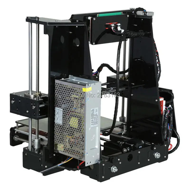
FDM (Fused Deposition Modeling) is the simplest and most common 3D prototyping technology in additive and industrial manufacturing, thanks to which general-purpose 3D printers have become available not only to commercial and industrial organizations, but also to individuals.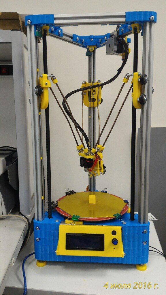 She appeared at 1988 in the kitchen of Scott Crump, the talented designer who two years later created the world leader in 3D hardware and 3D printing solutions, Stratasys. The print file is created mainly in the STL format, which allows you to segment the virtual model into layers. It is supported by all CAD CAD programs and is considered universal. The software package necessarily contains a slicer that reads data from the original layout and cuts it into layers. The consumable material in this printing technology is a plastic filament, which, when it enters the extruder, is heated to the melting temperature and dosed through the nozzle onto the working surface of the 3D printer. So layer by layer, the thickness of which depends on the capabilities of the printer, a finished object is grown on the desktop, the contours and geometry of which exactly correspond to a virtual prototype that until recently existed only on a computer screen. A wide range of plastic filament, presented on the modern market of consumables for 3D printing, makes it possible to produce finished products and their fragments of various sizes, types and purposes, determined by the physical and chemical properties of the material.
SLA - stereolithography
This additive technology is based on the printing of models and their fragments from liquid photopolymer resins, cured under the influence of an ultraviolet laser or a similar energy source. Stereolithography is the very first 3D printing technology, invented in 1984 and patented in 1986 by Charles Hull, who designed the world's first apparatus for making dense physical objects by layering a liquid photopolymer. As in the case of a plastic thread, the model is grown by layer-by-layer laser drawing of the outlines of the model - at the points of contact with the laser, the photopolymer freezes. As each layer is formed, the work platform is immersed in a tank filled with liquid resin to level the surface. This cycle is repeated as many times as needed to complete the prototyping process. The main advantage of stereolithography is its high accuracy; the layer thickness, depending on the capabilities of the printer, can reach 15 microns, which is several times thinner than a hair.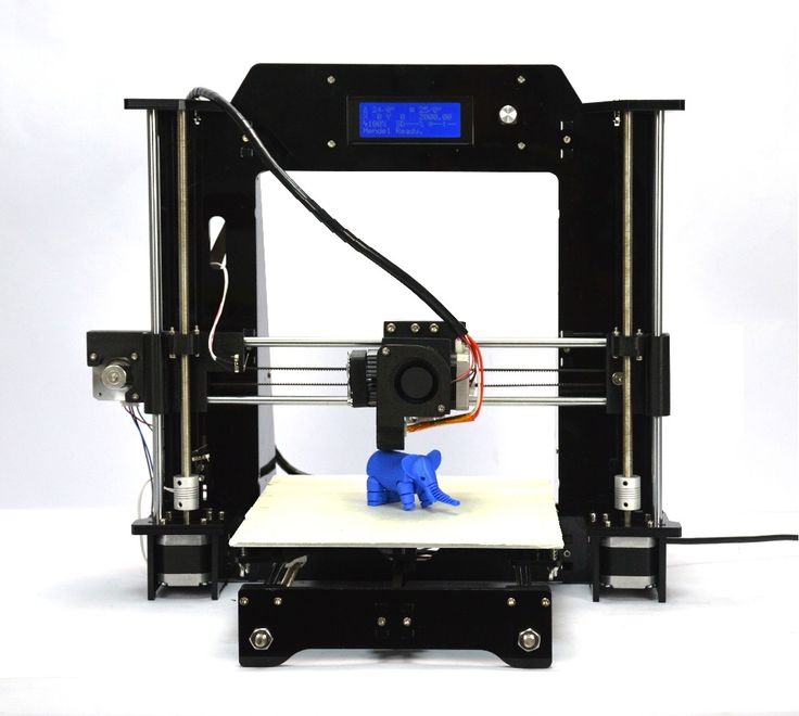 This explains the demand for SLA in digital medicine, in particular dentistry, and jewelry. Industrial models of printers for SLA printing allow you to create objects up to several meters in size.
SLM - Selective Laser Melting
This additive prototyping method is based on the use of a high power fiber laser. The main consumable material is a powder metal alloy. The developers of this technology are employees of the Institute for Laser Technology Wilhelm Meiners, Konrad Wissenbach and employees of F&S Stereolithographietechnik GmbH Dieter Schwarz and Matthias Fokele. An interesting fact is that Schwartz still works in the former F&S, which eventually turned into SLM Solutions GmbH, and Fokele created the main competitor of this company, ReaLizer GmbH. But back to technology. SLM allows you to print objects with an accuracy of 20-100 microns; a layout in STL format is used as a drawing of a future product. A thin layer of powder is applied to the working surface, which is located in a chamber filled with an inert gas (mainly argon).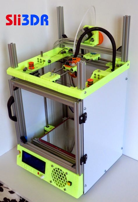 The complete absence of metal contact with oxygen prevents its oxidation, which makes it possible to work even with titanium alloys that are difficult in terms of processing. Each new layer is fused with the previous one under the influence of a laser beam directed in the coordinate plane. Stainless and tool steel, gold, silver, aluminum, titanium and alloys based on cobalt and chromium are used as consumables. This technology is considered the best for manufacturing thin-walled objects with complex geometry, which are successfully used in the engineering, aerospace, automotive, and medicine industries. The most similar technologies are direct metal laser sintering (DMLS) and electron beam melting (EBM).
SLS - Selective Laser Sintering
Another additive manufacturing technology used for printing functional prototypes and small-scale production. Its essence lies in the sequential layer-by-layer sintering of powder consumables using high-power lasers. SLS is sometimes confused with SLM, but the difference between the two methods is enormous. The first provides only partial melting of the powder raw material, the degree of which is sufficient to ensure reliable adhesion of the layers. The second is based on complete melting and is used for the production of monolithic models. The founders of SLS are Carl Deckard and Joseph Beeman, employees of the University of Texas localized in Austin, working on projects of national importance, including defense ones. Powdered plastics and metals are processed by one or more carbon dioxide (usually) lasers - sintered to form a physical object. Its contours are gradually drawn in accordance with the digital model. One of the features of objects made by this method is that their density is determined not by the duration of irradiation, but by the maximum energy of the emitter. Another characteristic feature is the complete absence of the need to use a support structure, which is typical for FDM and SLA, since the support of the hinged elements of the future model is provided by unused material.
DMLS - direct laser sintering
This technique was developed by the well-known Munich company EOS and is used for the production of metal products. The file in STL format, already well known to us, is divided into drawings before starting printing, each of them is one of the layers created when building the model. The sintering of metal powder is provided by sufficiently powerful fiber-optic lasers. A small amount of metal is fed into the build chamber and leveled using a special roller. The laser head moves along the contours specified in the drawing and sinters fresh powder in accordance with the contour of the future product, and so on until the finished object is in front of you. The main charm of this technology is its high accuracy, the layer thickness reaches 20 microns (for comparison, most personal FDM printers have a maximum accuracy of 100 microns). Increasing the number of lasers can significantly reduce prototyping time without sacrificing accuracy - today it is one of the most productive professional industrial technologies.
EBM - Electron Beam Melting
Electron Beam Melting is another additive technology for working with metals, somewhat similar to SLM technology, but with higher productivity. The key difference from other rapid prototyping methods is that in this case, instead of a laser, an electron emitter is used as an energy source. During the melting process, a high-power electron beam affects the metal powder, which is located in the vacuum building chamber. The layers of the future object are grown gradually, without contact with oxygen and other active gases, which ensures the high density and strength of the final product. This is the main advantage of EBM, which can give odds to all other additive technologies for working with powder consumables.
LOM – 3D lamination
This method was developed by the world-famous 3D company Helisys Inc and belongs to rapid prototyping technologies. Its essence is in the sequential layer-by-layer bonding of film or sheet materials (metal foil, plastic and even paper). The contour of each new layer is determined by the laser cutting parameters. The printing process is as follows: the first layer of material with a pre-applied adhesive layer is placed on the working platform, the laser draws the contour of the future product, the excess material is cut off, the platform with the finished layer is moved down, a new sheet is fed into the camera. Of course, the resolution is inferior to stereolithography or selective laser sintering, but on the other hand, three-dimensional lamination makes it possible to produce dense and large-sized products that respond well to post-processing. The features of LOM include the need for post-processing of the finished object, as well as the fact that the layer thickness depends on the selected production material. This is the most accessible and inexpensive method of 3D prototyping due to the low cost of consumables.
SGC - stereolithography mask
This 3D printing technology appeared in 1986 in Israel. It is based on high-precision layer-by-layer construction of a model using photopolymer resins and subsequent UV irradiation of a physical photomask of the future product, or on the so-called mask (hence the name). As a result, the material polymerizes, the excess is removed from the working chamber, and all cavities are filled with wax. At the end of each stage of model building, surface machining is possible, after which the printing process is resumed. At the very end of the process, it is necessary to melt the wax. The polymer resins used as consumables are similar in density and viscosity to ABS plastic. This makes it possible not to use supporting structures in the printing process, as in SLA prototyping, and, in addition to high accuracy in the horizontal plane, to achieve high resolution in the vertical. It should be noted that today SGC in its pure form is practically not used - it was replaced by a more advanced FTI technology, reminiscent of digital LED printing.
DLP - Digital LED Printing
Today, this relatively young technology is considered one of the most worthy alternatives to laser stereolithography - it is also based on the processing of photopolymer resins, which allows achieving amazing accuracy in prototyping. Instead of lasers, DLP printers use LED light projectors that form not only the contour of the future model, but the entire layer. DLP technology is in demand in digital dentistry, souvenir production, in the field of free design and jewelry, 3D printers working in it are gradually replacing SLA equipment. The advantages include excellent accuracy (up to 15 microns), a wide range of mechanical and physico-chemical characteristics of photopolymer resins and a large selection of colors.
MJM - Multi-Jet Modeling
This additive manufacturing technology is proprietary - it was developed and patented by the world famous company 3D Systems for use in the ProJet line of professional 3D printers. The uniqueness of this method is that it combines all the best features of FDM, SLA and 3DP (three-dimensional inkjet printing) technologies. The range of consumables is quite wide - it includes thermoplastics and waxes that gradually solidify as the model cools, as well as photopolymer resins that polymerize under UV exposure. Wax can also be used to build auxiliary support elements, and its low cost significantly reduces the cost of prototyping. MJM printers are indispensable in the production of samples and parts, the requirements for accuracy of which are high. They are in demand in digital dentistry, jewelry, engineering, and industrial design.
3DP - inkjet 3D printing. 3D printing technologies.
This method, developed by the Massachusetts Institute of Technology, is one of the oldest, and it owes its distribution to the Z Corporation, which was subsequently absorbed by 3D Systems. Like any additive technology, 3DP works in the key of layer-by-layer construction of a model or powder consumable of any type and purpose. After evenly distributing each new layer of powder over the working surface, the print head applies a binder to it. Each subsequent layer is glued to the previous one, forming a complete model. The very first 3DP printers used gypsum as a consumable; today, in addition to dyes and sealants, extruders also do an excellent job with plastics, sand mixtures, and some metal alloys.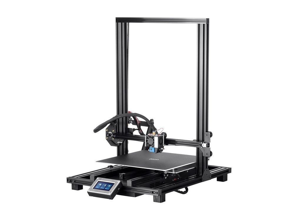 The technology itself is inexpensive, but in most cases the product requires additional post-processing and improvement of strength characteristics. Another advantage of the method is the absence of the need to use support structures, as in FDM and SLA technologies. 3DP and its modifications are used in a wide range of fields, in particular in bioprinting aimed at growing organic tissue.
CJP - Color Inkjet
CJP is a variant of 3DP that uses powder consumables that are printed with a resin binder on a thin layer when printed. This technology can easily create multi-colored models with impressive geometric complexity, while unused raw materials can be used as a support structure or collected at the end of a print session for further use. Basically, CJP printers work with various plastics - from those resembling silicone and rubber in their characteristics to impact-resistant and thermally stable materials. Basically, equipment of this type is used in industrial and architectural design, animation. With a relatively low cost of production, the advantages of this technology also lie in high accuracy in the reproduction of geometry and the ability to create multi-color products.
SHS - selective thermal sintering
Like other technologies based on melting, this method involves sintering plastic or metal powder under the influence of a source of thermal energy - this is the only significant difference from the classic SLS. At the end of the formation of each layer, the working platform goes down, after which a new thin layer of consumable material is applied to the surface using a roller mechanism. Layer sintering is contour, it corresponds to the virtual model. Such 3D printers have a lower energy efficiency and can only work with selected consumables - plastics and low-melting metals, which limits their scope. However, they are popular in the field of industrial design and custom production of objects with high demands on detail.
EBF
3 - Production Electron Beam Melting This is a high-tech modern additive method developed by NASA to produce models that are of such high quality that they do not require post-processing and can be used immediately for their intended purpose.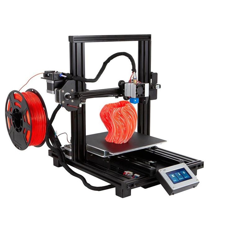 The key feature of EBF 3 is the gradual addition of material, which significantly reduces its consumption and at the same time ensures high accuracy in layering. As a result of printing, you get an almost finished product - it is characterized by accuracy in geometric compliance with a virtual prototype, excellent density and surface quality. The chamber for melting metal (the main consumable) is vacuum, the contour is fixed by a moving electron beam, a thin metal wire is fed to the focus point. The metal instantly solidifies, which makes the printing process even faster. This technology can print high-precision, geometrically complex objects ranging in size from a couple of millimeters to a couple of meters.
SDL - selective deposition lamination
Lamination using selective deposition has nothing to do with the LOM technology already familiar to us - in SDL, cutting is performed with specialized blades, and only certain fragments of the future object are glued using a printer.