Ciclop 3d scanner forum
Page Not Found
All AllMARKETPLACEGearbest SelectionAppliancesCell Phones & AccessoriesWomen's BagsComputers, Tablets & OfficeConsumer ElectronicsDrones, Toys & HobbiesHealth & Personal CareHome Improvement & ToolsHome & GardenIndustrial & ScientificMotor & Car ElectronicsOutdoors, Fitness & SportsWatches & JewelryWomenWomen's FashionMen's Fashion
Product keywords- Category
- Consumer Electronics
- Industrial & Scientific
- Cell Phones & Accessories
- Appliances
- Outdoors, Fitness & Sports
- Computers, Tablets & Office
- Health & Personal Care
- Home Improvement & Tools
- Drones, Toys & Hobbies
- Home & Garden
- Motor & Car Electronics
- Men's Fashion
- Watches & Jewelry
- Gearbest Promotion
- SUPER DEALS
- APP ONLY
- NEW ARRIVALS
Please enter the email address account
I agree to Gearbest Privacy Policy and Terms and Conditions.
I confirm all information provided is my own; I understand and agree it will be used as per the Gearbest Privacy Policy ; I can withdraw my prior consent at any time
Ciclop - Informatie en onderdelen
3D Scanner
Ciclop
Website / Bron
Informatie (ENG):
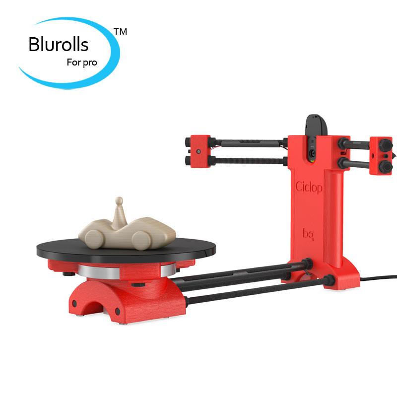
We are pleased to present Ciclop, the first DIY 3D scanner from BQ, together with the 3D scanning software Horus.
As with the other BQ DIY products, Ciclop and Horus are open source, which is why they belong to the Technological Heritage of Humanity. All the information on the mechanical design, the electronics, the software, algorithms, mathematics and experiments made will be available to the community.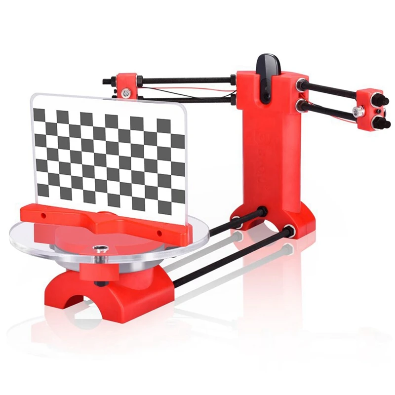
This enables anybody to study and understand the functioning of the scanner, as well as making modifications, improvements and developing new versions. We want to contribute and drive forwarde the development of these devices.
The scanner is based on major projects from our Technological Heritage which have been developed in the community, such as: GNU/Linux1, Python2, Reprap3 and Arduino4, among others. They have all our admiration, recognition and gratitude, as they have been fundamental in accomplishing this project.
State of the art
Several alternatives exist for capturing the three-dimensional geometry of an object, such as laser triangulation, structured light and stereo vision. Comparatively, the first method offers greater precision and a higher resolution, but it also has limitations in terms of the kind of materials that can be scanned. Laser triangulation is based on capturing the projection of a laser beam over an object using a camera.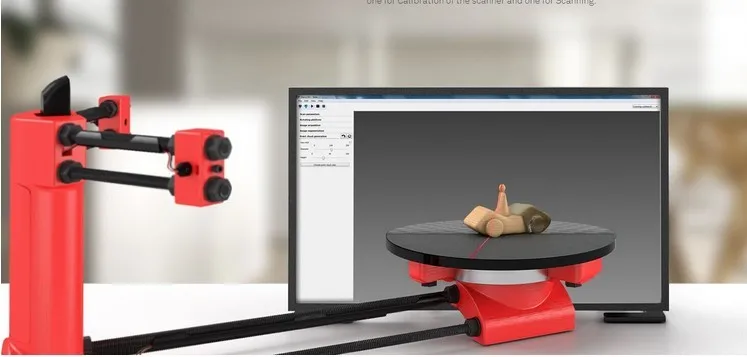
There are already scanners on the market with prices ranging from €500 to over €20,000 which are not open source, so the user is not able to study or modify the software.
FabScan5 and MakerScanner6 feature among these open source scanners, but they are not available for purchase as kits and the materials must therefore be purchased separately.
Design
The structure of Ciclop is made up of 3D-printed pieces, M8 threaded rods, M8 screws, M3 screws, nuts and washers. It has a 20 cm diameter methacrylate platform on which the piece is placed for scanning. It is covered with a anti-slip surface to prevent objects from moving during the scanning process.
The platform is supported by a 110 mm diameter ball bearing. The movement is created using a Nema 17 stepper motor.
Parts
3D Prints:
Electronics:
| Part Number | Description | Qty | Units |
|---|---|---|---|
| G003657 | ZUM BT328 rev2 | 1 | PCs |
| C03I050003 | USB wire 1.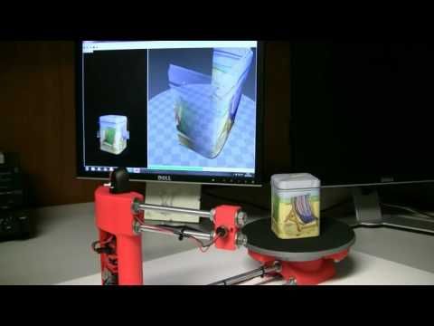 2m for charger 2m for charger | 1 | PCs |
| C04H010020 | Stepstick Drivers A49988 4 layers (with heatsink) | 1 | PCs |
| C05C020001 | Power supply 12V-1.5A | 1 | PCs |
| C05I070002 | M3x10 Screw - DIN-912 Class 8.8 Black | 10 | PCs |
| C05I070004 | M3 Nut - DIN 934 Class 8 Black | 6 | PCs |
| C05I070032 | M8 Nut - DIN 934 Class 8 Black | 28 | PCs |
| C05I070035 | M8 Washer - DIN-125 Class 8 Black | 18 | PCs |
| C05I070005 | Allen key s/long 2.5 Forum | 1 | PCs |
| C05I070068 | Bearing 16014 | 1 | PCs |
| C05I070086 | Ceramic screw driver trimmer for electronics | 1 | PCs |
| C05I070126 | Non-skid EPDM disk (200mm diameter) | 1 | PCs |
| C05I070127 | HD Webcam C270 | 1 | PCs |
| C05I070128 | MOTOR 42BYGHW609P1-X11 [Nema 17] | 1 | PCs |
| G003527 | ZUM SCAN Shield | 1 | PCs |
| G003803 | M8X400MM Black threaded rod | 2 | PCs |
| G003804 | M8X292MM Black threaded rod | 1 | PCs |
| G003805 | M8X170MM Black threaded rod | 4 | PCs |
| G004291 | M8x30 Screw - DIN-933 Class 8.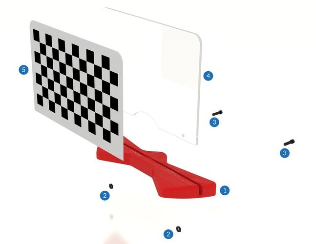 8 Black 8 Black | 3 | PCs |
| G003807 | 200x8 MM Acrylic cylinder | 1 | PCs |
| G003810 | 3D Scanner Calibration Sticker | 1 | PCs |
| G004066 | CICLOP 3D Scanner Methacrylate Pattern | 1 | PCs |
| G003976 | CICLOP 3D Scanner Printed Motor Support Red | 1 | PCs |
| G003979 | CICLOP 3D Scanner Printed Camera Support Red | 1 | PCs |
| G003982 | CICLOP 3D Scanner Printed Electronic Cover Red | 1 | PCs |
| G003985 | CICLOP 3D Scanner Printed Laser Support Red | 2 | PCs |
| G003988 | CICLOP 3D Scanner Printed Fitting Motor-Disk Red | 1 | PCs |
| G003997 | CICLOP 3D Scanner Printed Disk Support Red | 1 | PCs |
| G004063 | CICLOP 3D Scanner Printed Pattern Support Red | 1 | PCs |
| G004000 | CICLOP 3D Scanner Printed Clip Bearing Red | 3 | PCs |
| G003991 | CICLOP 3D Scanner Printed Motor Cable Conduit Black | 1 | PCs |
| G003994 | CICLOP 3D Scanner Printed Laser Cable Conduit Black | 2 | PCs |
| Red Line Laser, 5V, 60º, class 1, with connector | 2 | PCs | |
| G004134 | Antislip Pads Transparent h4.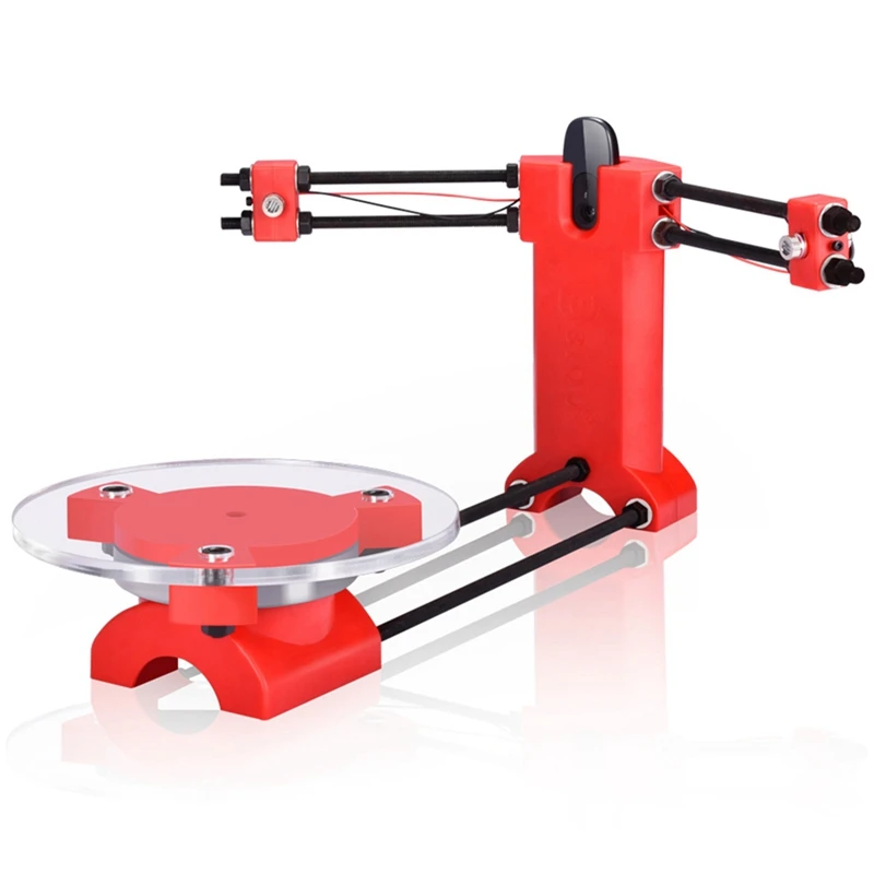 5mm W12.7mm 5mm W12.7mm | 6 | PCs |
Download Ciclop @ Github
Download Ciclop @ Thingiverse
3D scanner Ciclop. With my own hands.
Ciclop 3D Scanner by bqLabs
http://www.bq.com/gb/products/ciclop.html
http://diwo.bq.com/en/ciclop-released-2/
Firmware code https ://github.com/bq/horus-fw
HEX firmware http://diwo.bq.com/en/horus-fw-released/
Uploading Hex firmware http://russemotto.com/xloader/
Experience Cyclops buildings "Ciclop 3D scanner - the devil is in the details!"
Discussion of my research on TriDeshnik http://3deshnik.ru/forum/viewtopic.php?f=8&t=15
Now you need to smartly split the part camera-holder.stl
Cleaned it from supports. You can download a blank part. While I will cut into three parts for twisting with screws.
Cut into three parts for twisting with M3x10 screws. Download archive with stl models.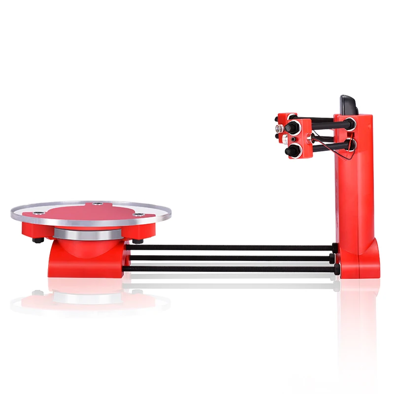
General wiring diagram for stepper motor driver
Connecting to Arduino Nano
0011
General assembly scheme
Table assembly
3 - M3x10 screw 5 pieces
4 pieces - M3 nut 1 piece 6 - M3x0.0 bolt Screwed into the disc (10). You can take the M8 screw "in the secret" and screw it in from top to bottom, tightening it with a nut at the bottom.
Installation and fixation of lasers
2 - M3x10 laser housing fixing screw, 2 pcs
3 - M3 nut 2 pcs
4 - Laser 2 pcs
Sawing
1 - M8x400 threaded stud 2 pcs.
2 - M8 nut 28 pcs.
3 - M8 washer 18 pcs. Laid between the nut and the plastic part
4 - Cable duct. Can be replaced with electrical tape
5 - M8x292 threaded stud 1 piece
6 - M8x170 threaded stud 4 pieces. Hold lasers. I think it's more reasonable to put thinner studs here
7 - Cable channels 3 pieces.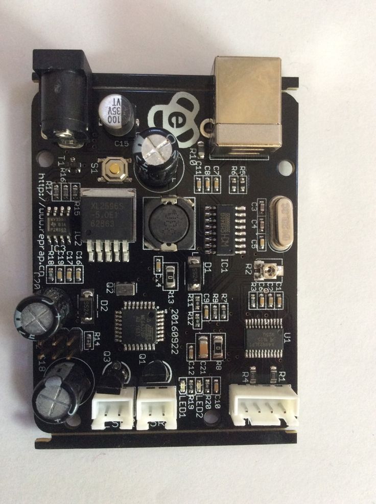 Can be replaced with duct tape or heat shrink
Checkerboard pattern holder assembly
2 - M3 nut 2 pieces
3 - M3x10 screw 2 pieces
4 - plywood cardboard
5 - chess paper-sticker. pdf, svg
Assembly video
Until I started to assemble myself, it seems to me that this is enough for the assembly. In the course of the infa will change and be supplemented.
Assembly
Brutal bearing
Paste the leather on the table
Soldering wiring on the driver
As a result, I have to do it on the Arduino Uno, since I miscalculated with Nanami.
I've already stumbled on connectors in UNO;)
We've arrived. Horus does not see UNO's COM port.
And in the device manager, instead of Arduino UNO, it says Ch440. It looks like you have to reflash the bootloader.
Here is the correct scheme for flashing UNO (Duemilanova) via MEGA 2560.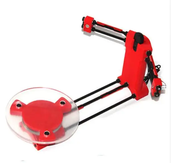 Only I have a 100 microfarad conduit (probably will do). I will check.
Bootloader firmware steps in Arduino UNO ( Duemilanova), via Arduino Mega:
[ Click to read ]
step 1 - Nothing is connected to the Mega, except for the USB cable. Launch the Arduino IDE. We set the Mega parameters: Board, Processor, Port.
step 2 - Go to menu File -> Samples and click ArduinoISP. The sketch of the ArduinoISP programmer is loaded into the editor. Press the round button with an arrow to the right "Upload" and upload the sketch to Mega.
step 3 - Disconnect Mega from everything and connect to UNO (Duemilanova) according to the scheme (above). And we also stick a capacitor (I have 100 microfarads). We connect Mega via USB to the computer.
step 4 - Now in the Arduino IDE set the parameters for UNO (Duemilanova): Board, Processor, Port Now our Mega has become a programmer.
step 5 - Flashing the bootloader on UNO (Duemilanova) via Mega.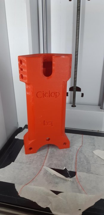 In the Tools menu, click "Burn bootloader". Both boards should have blinking LEDs. Ready. We disconnect everything.
I tried to reflash Bootloader according to the scheme in UNO. Everything blinked and flooded, but in the end nothing came of it. Apparently the fuses are wrong.
The Arduino Nano was released and I connected it to the computer. In the device manager I see Ch440 again, but it's working. I launch Xloader and upload HEX firmware. Everything goes like clockwork. I connect UNO - Xloader hangs on the firmware, the LEDs do not blink. I read that Duemilanova can be disguised as UNO. Well, what the hell is not joking, I decided to flash a bootloader from this Duemilanova on it. The LEDs flashed - there is life. I upload HEX firmware and "lo and behold" it is uploaded. That's what "correct fuses" means :-)
These are the settings I set in Chorus, otherwise it doesn't work. I entered the COM port myself, since it automatically determines incorrectly (defines Mega from a 3D printer) and does not provide a choice.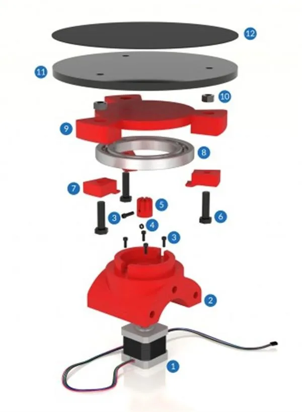 3deshnik Greetings to all. Today is a small review of the Ciclop desktop scanner.
Once again, the store offered to take something for review. Since I have long been interested in the question of using this thing for the needs of decorative 3d printing, I chose a scanner.
So, the scanner itself was developed by the Spanish company BQ, which has now ceased its support (supposedly due to Chinese fakes, but it is doubtful. Now the American CowTech also sells this scanner. The source codes for 3d printing of parts of the scanner are freely available at Thingiverse (there are also links to software and electronics).0010
Links to full documentation sets:
www.cowtechengineering.com/downloads
www.bq.com/ru/support/ciclop/support-sheet there are a few points:
1. It is not worth rushing to tighten all the nuts - you still have to adjust the geometric dimensions - the convergence of lasers in the center of the site, the distance to the turntable.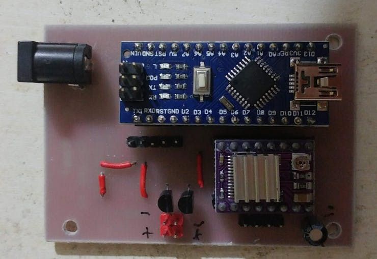
2. In my stand, the camera “dangled” a little, by a fraction of a millimeter - but that was enough to skew the picture. Eliminated by laying foam material.
4. The turntable was transparent and uncoated (as in the original) - I painted it with plastidip.
5. Check the calibration checkerboard patterns. I don’t know how they printed the one from my kit - but the proportions of the squares were violated. I took it from the Internet and reprinted it myself.
6. The focus of the camera is not adjusted to the distance to the platform. He removed the cover and twisted the focus in place.
88. The economy is managed by the "native" Horus software from BQ.
After assembly, the scanner went through calibration procedures in the native Horus software.
Since by this point I already knew that the quality of scanning is very dependent on the quality of lighting (stability, diffuseness, color temperature), I took care of having a small lightbox in advance in order to at least provide more or less comparable conditions for samples.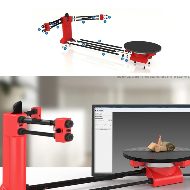
Having selected "candidates" for trials, I got ready.
The requirements for the object are as follows:
1. The object must be larger than 5x5 cm but smaller than 20x20 cm
2. The object must be opaque and still
3. The object must weigh no more than 3 kg
Difficult to scan:
1. Shiny, luminous objects
2. Too dark objects
3. Objects with a blurred surface (eg soft toys)
The result of the scan is a point cloud in PLY format (which must then be converted to a surface). Here is a guide for post-processing the cloud and preparing the STL file.
After reading the scan optimization guide, I decided to try with a simple cylindrical object.
After several attempts, I was convinced that I had a common problem - mismatches in the point clouds from the right and left lasers, and the issue with proportions.
We couldn't find anything worthwhile about this except an attempt to calibrate the webcam settings (they are not calibrated when the calibration wizard is running) (a dude named Jesus from BQ support has not answered questions for a long time). To do this, you need to take several shots with different positions of the calibration table. Done. The situation has improved, but not completely.
I had to manually edit the calibration file (calibration.json in the Horus-a folder) and by trial and error, scanning a cylindrical object, to achieve the coincidence of the clouds.
And everything seems to be ok:
But no - on complex objects, cloud fragments still sometimes do not coincide, besides, many “blind” zones are formed:
impossible, at least with regular lasers.
You can, of course, continue experimenting with scanning with separate lasers and trying to combine all this economy in third-party software, and then try to bring it into a viable form for STL.
All this is reminiscent of a joke about boats in bottles.
-How do you make boats in bottles?
-I put sand, silicate glue, sticks into the bottle and shake it.
It turns out all sorts of shit, and sometimes boats.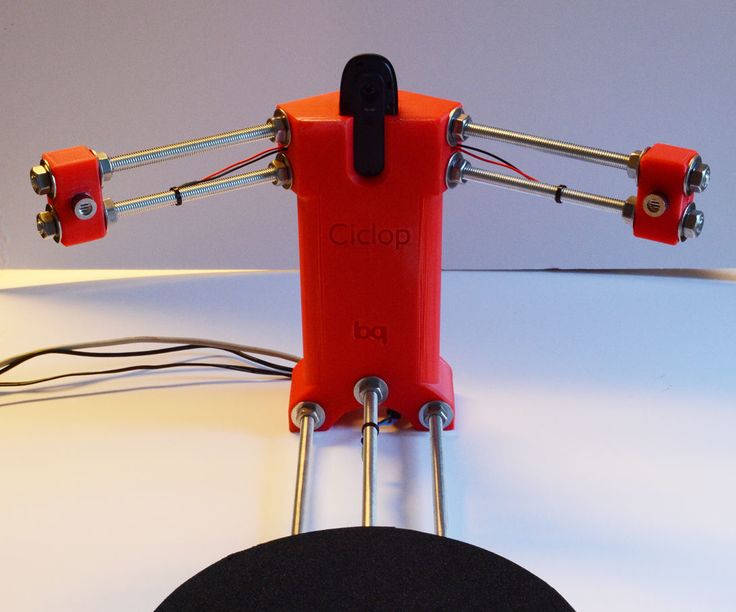
In general, I realized that I am not an adept of such creativity, and I have a suspicion that it is easier to model objects from scratch that are easier for a scanner.
And complex ones - the scanner cannot cope with complex ones in normal mode, two lasers are not enough for it - blind spots remain. To fix this problem, you need to scan in other positions and then again suffer with the combination of clouds. No thanks.
As a result - the thing will fit only for learning the basics of laser scanning, for something more - absolutely useless. No, of course, you can get something with outlines similar to the original model, but on this (and this, taking into account all the tambourines with cloud processing), that's it. No wonder the Spaniards abandoned this case.
The store made sure - in the description it is honestly stated that the result depends on the position of the planets and the mood of Aunt Sonya from the third floor.