Casting 3d printed parts
Introduction to Metal Casting and Ways to Combine 3D Printing With Casting Workflows
Metal casting is an age-old metalworking process in which molten metal cools and solidifies in a mold to form metal parts. Despite its ancient roots, metal casting is still one of the most popular processes for companies looking to produce metal parts.
This article will cover what metal casting is, how it works, and walks you through the most common metal casting processes and the benefits manufacturers can attain by combining modern digital tools like 3D printing with traditional casting workflows.
White Paper
Get design guidelines for creating 3D printed patterns, walk through the step-by-step direct investment casting process, and explore guidelines for indirect investment casting and sand casting.
Download the White Paper
Metal casting step-by-step from the original design through final casting.
Since the advent of metal casting, the methods have evolved and varied. Its core techniques, however, have remained constant. Here is a general step-by-step process for metal casting:
Ring patterns 3D printed in Castable Wax 40 Resin.
In order to begin the metal casting process, a manufacturer first must develop a representation of the desired pattern. This pattern is essential in designing the mold used for the cast. It is traditionally made from wood, foam, plastic, or wax and ensures that the mold accurately produces the finished metal part. Today, 3D printing is also a common method to produce patterns, which allows designers to create accurate patterns directly from digital CAD software tools.
A pattern is not an exact replica of the desired part. It has additional elements that make the casting process possible, including gates that allow molten metal to flow at a steady rate and vents for gas to escape. Additionally, patterns are also larger than the parts they represent to account for the shrinkage that occurs during cooling.
When the casting piece is hollow, the manufacturer also creates a core of sand or metal to shape the internal form. This core gets removed upon completion of the casting.
The next step is creating a casting mold, which can be either reusable (non-expendable) or non-reusable (expendable). Non-reusable molds are usually made out of sand, plaster, wax, or by 3D printing, and just as the name suggests, they get destroyed in the casting process. Reusable molds are made out of metal and other durable materials and can be reused for multiple casting cycles.
Ceramic shells after burnout and 3D printed patterns in Clear Resin.
Molten pewter poured into a High Temp Resin 3D printed mold for metal casting.
During this step, the metal gets heated in a furnace until it melts. Depending on the application, manufacturers can use a variety of different metals, with the most commonly cast metals being iron, aluminum, aluminum alloy, steel, copper, and zinc, as well as precious metals like gold and silver. Once the metal melts, the manufacturer pours it into the mold cavity and allows it to cool and solidify.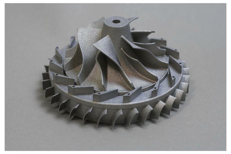
Metal casting post-production.
Once the metal cools down and solidifies, the parts get removed from the mold. Depending on the mold type, this can be done by vibrations in a shakeout process, washing away the investment material, or by ejector pins. Then, excess material, such as vents, gates, and feeders, are removed from the parts. Finally, the parts get filed, grated, machined, or sandblasted to smooth the surface and reach the final shape requirements.
Though all metal casting techniques share the same core process, there are various methods better suited for different applications. Some of the most common methods include die casting, investment casting, and sand casting.
Die casting uses a steel mold and high pressure. (Source: buhlergroup.com)
Die casting is a metal casting process in which a manufacturer pushes molten metal into a steel mold cavity at a high pressure to quickly produce metal parts. In die casting, the manufacturer fixes two halves of a die or reusable mold together and uses a nozzle to inject pressurized molten metal into the die. When the metal cools, the die opens, and ejector pins push out the cast.
The two most common die casting processes are hot-chamber and cold-chamber casting. While the specifics of these processes vary, there are several shared characteristics of the die casting process as a whole.
Hot-chamber die casting is the most common of the two main die casting processes. Hot-chamber die casting machines have a built-in furnace to heat the metal within the machine. Once the metal reaches a molten state, the machine lowers a cylindrical chamber into the molten metal. The gooseneck shape of the metal injection system allows the chamber to quickly fill itself, and then push the material into the mold with air pressure or a piston.
Immersing the injection mechanism to fill it allows for rapid and streamlined mold injection in this casting process. Because the chamber is subject to direct heat from the molten metal, however, hot-chamber die casting systems are at risk for corrosion, making them a less viable option for metals with high melting points.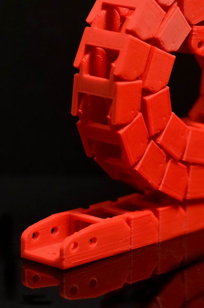 Instead, it is better suited for materials with low melting points and high fluidity, like lead, magnesium, zinc, and copper.
By contrast, the cold-chamber die casting process works more slowly to avoid corrosion. With this method, a foundry worker ladles molten metal into the injection system. A piston then pushes the metal into the mold.
This process limits the corrosion that is more common in hot-chamber die casting. It is an ideal option for metals with high melting points, like aluminum and aluminum alloy.
The die casting process is rapid and produces highly detailed parts. It is ideal for the production of high volumes of complex parts and can also produce strong parts with smooth surface finishes. Die casting’s capacity to produce a high volume of parts makes it a crucial process in the automotive and aerospace industries.
As die casting tooling and equipment are expensive, this process is not cost-effective for smaller production runs. In addition, the malleability of metals used in the process can impact the complexity of the product.
Cast parts from SLA patterns printed in Clear Resin on a Formlabs 3D printer.
Investment casting, also known as lost-wax casting, is a process that uses wax, slurry, and molds to produce complex parts. It is one of the oldest metal casting techniques but is still valued for its ability to create precise metal parts with intricate shapes.
This process is still widely used for producing jewelry, dentistry, and art. Its industrial form, investment casting, is a common way to create precision metal parts in engineering and manufacturing.
Investment casting patterns are typically made out of wax or 3D printed polymers. The patterns are assembled into a tree-like structure and dipped into a slurry of silica, or put into a flask and surrounded by the liquid investment plaster. After the investment material dries, the flask is placed upside down into a kiln, which melts the pattern, leaving a negative cavity in the shape of the original model. Metal is melted and then poured, using gravity or vacuum pressure to pull the metal into the cavity.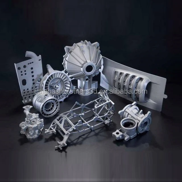 The casted parts are filed, ground, machined, or sandblasted to achieve final geometry and surface finish.
Sprue trees with cast rings.
Investment casting is a versatile process. It allows manufacturers to produce accurate and repeatable parts out of nearly any metal available for casting and complicated shapes that would be difficult or impossible with other casting methods. Casted parts also have excellent surface qualities and low tolerances, with minimal surface finishing or machining required.
These features make investment casting ideal for complex parts in automotive, aerospace, and industrial applications, medical tools, dental implants, as well as fine jewelry and art.
Investment casting is a complex and labor-intensive process. It requires specialized equipment, costly refractories and binders, as well many manual operations to make a mold. It can be difficult to cast parts that require cores and the process is better suited to small parts.
One half of a sand casting mold.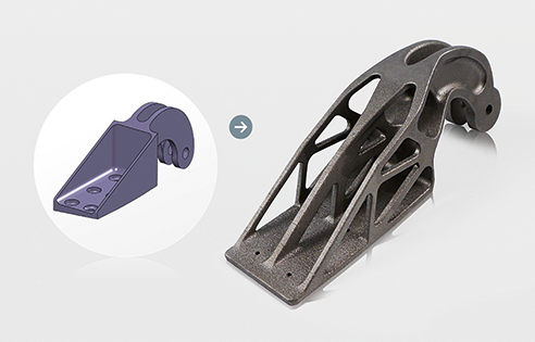
Sand casting is a metal casting method that was first in use 3,000 years ago but remains the most widely used casting method to this day. This process allows manufacturers to cast metal without relying on machining.
In the sand casting process, the manufacturer first creates a foundry pattern, or replica of the casting, most commonly from wood or plastic. The pattern is oversized to allow for shrinkage. Parts with features on one side only require an open-faced mold. For parts with multiple detailed surfaces, the manufacturer separates the foundry pattern into two mold boxes to form a closed cavity mold. The top half is called a cope and the bottom a drag.
Once the manufacturer creates the pattern, they tightly pack sand around the pattern. Then, they add sprues and gates to ensure that the molten metal flows smoothly through the mold cavity. The manufacturer removes the pattern then clamps the two halves of the sand mold together. Once the metal melts to a molten state, it is poured into the mold and left to cool.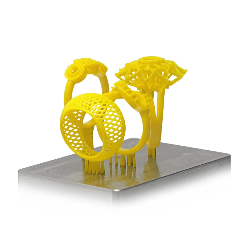 From here, the sand mold is removed using vibrations or high-pressure water. Finally, the manufacturer refines the part by removing sprues and gates, and polishing the cast metal part.
Sand casting is an adaptable process that functions outside the limitations of machinery. Because of this, it can create complex parts of virtually any size. Sand is inexpensive and plentiful, which lowers the setup cost and makes modifications possible. It is the only practical or economical way to produce very large castings. The lead time of sand casting is also short, making it a viable process for short production runs.
Sand casting’s versatility makes it a manufacturing option across a wide array of industries. It can produce medical equipment, automobile parts, electronic equipment, gas tanks, and engine blocks, and more.
Sand casting creates highly porous, textured metals. The shrinkage and rough surface finish also lower the dimensional accuracy of parts. This results in a low-strength final product that requires time-consuming post-processing to achieve a higher quality finish.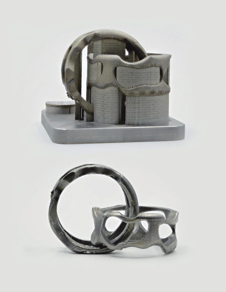
In order to choose the right industrial metal casting process, several factors must be considered. We’ve created this comparison table to help you compare die casting, investment casting, and sand casting in terms of types of metals, production volume, costs, production time, part complexity, and for which industries they are generally used.
| Die Casting | Investment Casting | Sand Casting | |
|---|---|---|---|
| Compatible metals | Aluminum, copper, lead, magnesium, zinc | Most metals | Most metals |
| Production volume | High volume | Low to high volume | One-off to medium volume |
| Unit costs | Low | Moderate to high | Moderate |
| Tooling costs | High | Moderate | Low |
| Cycle time | Rapid | Long | Moderate |
| Industries | Automotive, aerospace, consumer products, furniture, power tools | Automotive, aerospace, jewelry, medicine, dentistry, art | Automotive, aerospace, industrial equipment, electronics, consumer products |
3D printed jewelry ring pattern and cast metal part.
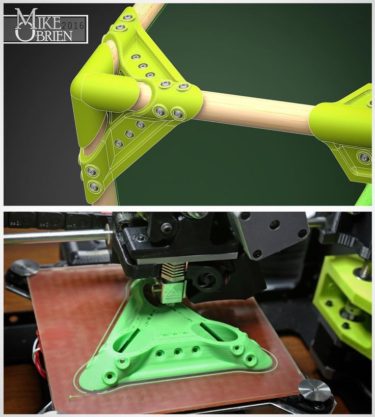
Engineers, designers, jewelers, and hobbyists can capitalize on the speed and flexibility of 3D printing by combining castings processes like indirect investment casting, direct investment casting, pewter casting, and sand casting with 3D printed patterns or casting metal into 3D printed molds. Cast metal parts using 3D printed rapid tooling can be produced in a fraction of the time invested in traditional casting and at a significantly lower cost than metal 3D printing.
Stereolithography (SLA) 3D printers offer high precision and a broad material library that is well-suited for casting workflows and can produce metal parts at a lower cost, with greater design freedom, and in less time than traditional methods.
Webinar
In this webinar, we will look at how desktop stereolithography (SLA) 3D printers are being used to directly print patterns, how to work with SLA patterns for investment casting, and how the benefits of generative design are increasing the demand for printed patterns.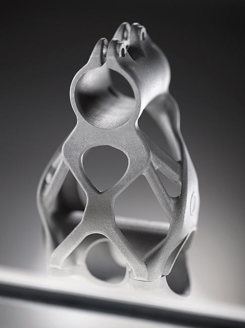
Watch the Webinar Now
A 3D printed mold in Clear Resin for wax injection.
The process of making patterns from molds or tooling is referred to as indirect investment casting because it requires creating molds for producing the patterns in addition to final investment molds.
Rigid molds for wax (often referred to as tools) are commonly fabricated by machining aluminum or steel. Machined metal molds cost thousands of dollars to produce and take weeks of machining and polishing work before first shots can be run and pattern parts evaluated within a casting process.
With 3D printing, manufacturers can directly 3D print the mold for their pattern using materials like High Temp Resin or Rigid 10K Resin, resins with high-temperature resistance. For an optimal surface finish of molded parts, treat the interior surfaces of the mold by sanding and polishing for a smooth look, or bead blasting if a uniform matte look is desired. To ensure the final cast parts are dimensionally accurate, compensate for shrinkage by scaling up the printed mold.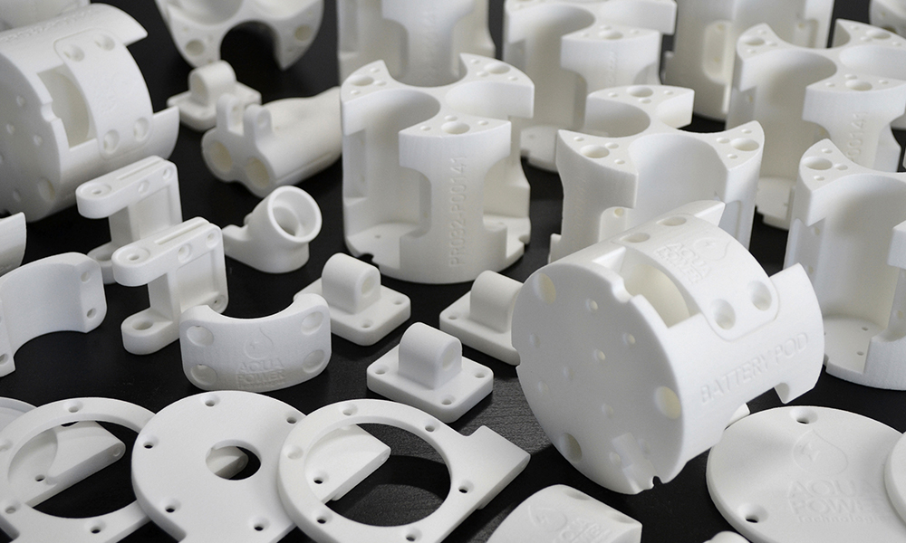 The exact shrinkage of the wax and the casting process can be obtained from supplier specifications.
3D printed molds for metal casting shorten the time between concept and first tests to a matter of days because manufacturers can directly print the tooling necessary for running and evaluating parts.
While molded pieces must follow design rules for moldability (e.g., no undercuts, draft is beneficial, etc.), you can achieve increased pattern complexity by using assembly jigs to combine multiple components into a single structure.
White Paper
Download our white paper to learn about six moldmaking processes that are possible with an in-house SLA 3D printer, including injection molding, vacuum forming, silicone molding, and more.
Download the White Paper
3D printed jewelry patterns and metal casted rings.
Direct investment casting is a version of investment casting where the process moves directly from pattern creation to surrounding the pattern with investment material. It is ideal for producing parts with geometries that are too complex to be molded or for parts with extensive undercuts and fine surface texture details, where molding is possible but carries high tooling costs.
Traditionally, patterns for direct investment casting are carved by hand or machined if the part is a one-off or expected to be only a handful of units. With 3D printing, however, manufacturers can directly print the patterns, removing the design and time constraints common in other processes.
With 3D printing, engineers, designers, and jewelers can direct 3D print patterns in order to achieve shorter lead times and geometric freedom that exceeds the design for manufacturability constraints of molding processes. Formlabs developed a range of castable materials suitable for direct investment casting, in particular for the jewelry industry.
White Paper
The way jewelers work is changing, and castable photopolymer resins are leading the way.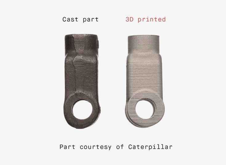 In this guide, learn how to cast fine jewelry pieces 3D printed on Formlabs printers.
Download the White Paper
Sample part
See and feel Formlabs quality firsthand. We’ll ship a free sample part to your office.
Request a Free Sample Part
Grey Resin printed pattern and finished aluminum casting from an open-faced sand mold.
Similar to investment casting, 3D printing can be used to create patterns for sand casting.
In comparison to traditional materials like wood, 3D printing allows manufacturers to create complex shapes and go straight from digital design to casting.
Metal Miniatures made with pewter casting and 3D printing.
Pewter is a malleable metal alloy with a low melting point that can be used for making fully metal objects for decorative applications such as detailed metal miniatures, jewelry, scale models, and replicas of antiques.
With recent developments in temperature-resistant 3D printing materials, like High Temp Resin for Formlabs SLA 3D printers, it’s now possible to 3D print molds for direct pewter casting.
There are two options for mold designs: a sacrificial or pull-apart mold. In a sacrificial mold, there is a shell designed to be broken apart in the process. Pull-apart molds function with separate halves so the mold can be reused.
Compared to directly printing metal, the casting pewter in 3D printed molds offers significantly better detail and surface finish at a small fraction of the cost. Compared to wax casting, directly 3D printing a mold has fewer steps and requires less manual effort, while preserving the most possible detail.
Webinar
Watch our webinar to learn how moldmaking using 3D printed masters and reusable or sacrificial molds can allow you to produce parts in porcelain, precious and non-precious metals, silicone and biocompatible flexible materials, and more.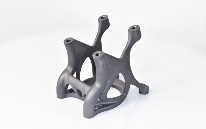
Watch the Webinar Now
Jewelry investment casting process with 3D printed patterns.
Businesses looking to boost design freedom or cut costs and lead times have a strong solution in metal casting with 3D printing.
Certain types of complex metal castings, such as large shapes with cross-sections and pieces with multiple cores, are difficult to create using traditional metal casting methods. 3D printing allows manufacturers to produce these complex designs. For example, jewelers can create intricate and custom designs that might be impossible without a 3D printed pattern.
3D printing also eliminates reliance on multiple machines or service providers to create parts. Instead, companies just need a digital file, a 3D printer, and printing material. This can cut costs and waste, as all the material used goes into the final product.
Finally, the combination of 3D printing with metal casting can cut costs and lead time.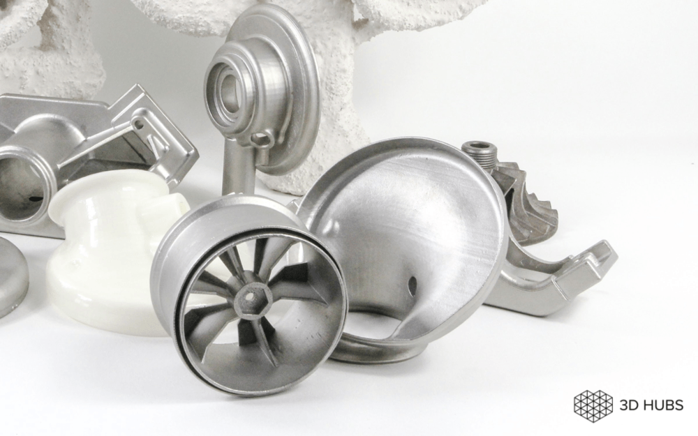 Rather than waiting weeks for expensive tooling before being able to cast a final product, a 3D printer can create a pattern or mold in hours.
Metal casting combined with 3D printing help companies quickly and efficiently create metal parts. With a Formlabs SLA 3D printer, you can expedite the metal casting process and cut costs along the way.
Learn more about the Form 3 desktop SLA 3D printer and request a free sample part to evaluate the quality firsthand.
See the Form 3Request a Free Sample Part
Producing low-cost cast metal parts using 3D printing
Learn how castable FDM prints can be used to produce low-cost metal parts via investment casting.
Using 3D printing to produce metal parts
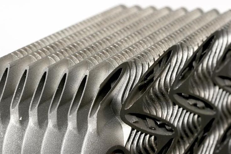
DMLS
DMLS is a powder bed fusion technology that is used to produce metal parts to a high level of dimensional accuracy. The additive nature of 3D printing means that very complex designs are able to be created. The design freedom offered by DMLS has seen it adopted by many industries (automotive and aerospace) where weight optimisation and performance are critical (the cost of operating a commercial aircraft is roughly €1000/kg meaning any weight saving result in significant savings in operation costs). This has seen these industries willing to justify the high per part cost of DMLS based on the cost savings of producing complex lighter parts. It is always advisable to compare the cost of using a 3D printing service provider and buying your own metal 3D printer.
DMLS can produce parts from a large range of metals including aluminium and stainless steel as well as exotic biocompatible materials used in dentistry and medical industries like titanium. The main limitations of DMLS are the high cost, small build size and long lead times compared to other 3D printing technologies. Parts also require support material to limit the likelihood of distortion and warping occurring and this must also be removed after printing further increasing lead time and cost.
A large number of metal crown and bridge copings printed in a single print(image courtesy of Renishaw)
Investment casting
The investment casting process traditionally uses wax patterns to produce molds for casting, as it has a very clean burn-out with no residues.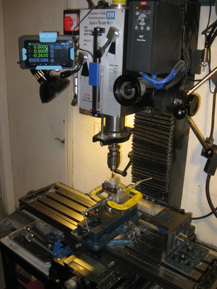 The image below presents the process.
For low-run investment casting, patterns are traditionally machined from a wax block via CNC. Alternatively, for larger series, a die is machined and the patterns are created by casting the wax using the die. Tooling is a very expensive investment with production of the dies often taking a very long time (2 - 6 weeks).
3D printing is now regularly used in conjunction with a range of investment casting applications to produce patterns from castable materials. Castable 3D prints are commonplace in the dental and jewelry industries and are generally produced via the SLA / DLP printing process. This is a vat-photopolymerization technology that is able to produce parts with a very smooth surface and extremely fine details. The main limitation around SLA is the printer build volume size, or the high cost involved for larger patterns. For larger metal parts, castable FDM offers a cost effective, rapid solution.
Small, intricates design are perfect for SLA investment casting. The image above shows a castable pattern (left) printed via the SLA process and the final cast ring (ring)
(image courtesy of Formlabs)
For larger metal parts, castable FDM offers a cost effective, rapid solution.
Ready to transform your CAD file into a custom part? Upload your designs for a free, instant quote.
Get an instant quoteInjection molding from 3D printed molds
Study of low-volume production of small plastic parts
BRIEF INFORMATION
Form 2 printer and injection using a Galcom Model-B100 injection molding machine. Two transparent resin molds were tested: one large butterfly mold and one mold with four small butterflies in one block. A third mold for the USB stick case was tested in high temperature polymer. These molds were 3D printed by Formlabs and the castings were made by Galomb Inc and Formlabs in a variety of materials.
Formlabs and Galomb, Inc.
LOW-VOLUME 3D PRINTED PARTS PRODUCTION
Most of the plastic products in the world today are made by injection molding. Using inexpensive desktop 3D printers and injection molding machines, molds can be created to produce small functional parts from manufacturing plastics.
For low volume production (approximately 10-100 parts), 3D printed molds save time and money. They also allow for a more flexible approach to manufacturing, giving engineers and designers the ability to easily modify molds and continue iterating their designs at low time and cost.
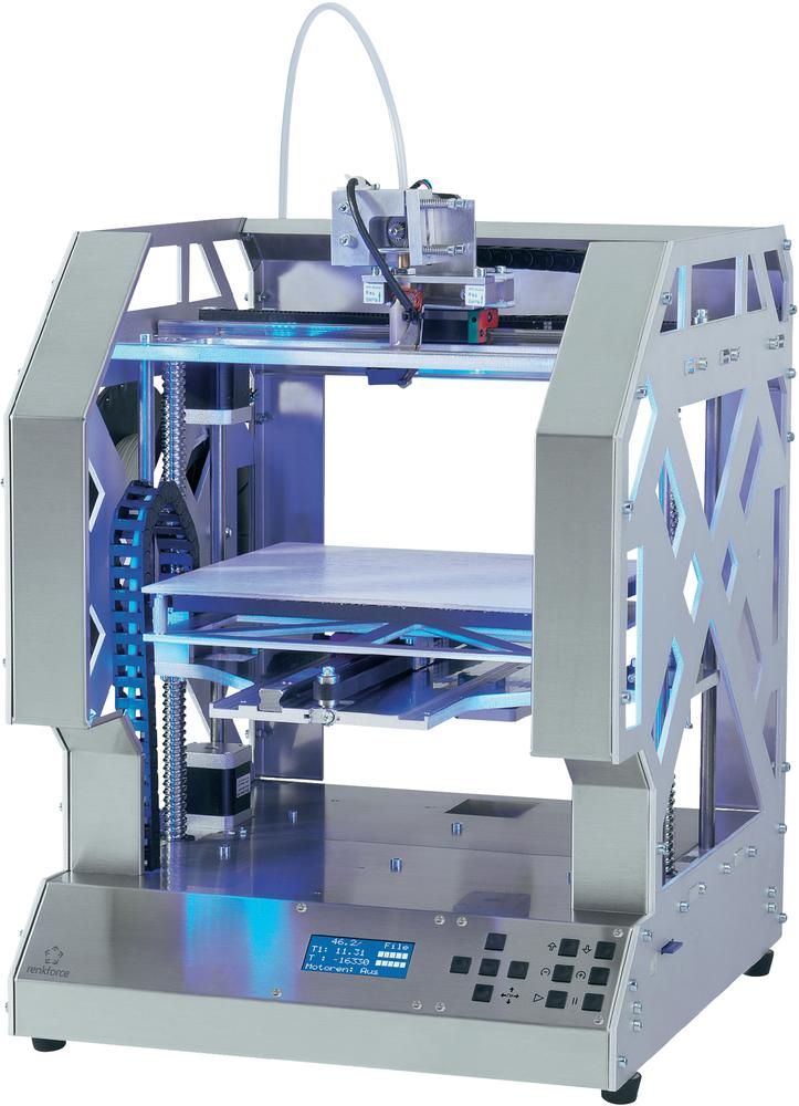
The Form 2 Stereolithographic 3D Printer (SLA) produces completely solid, smooth parts that can withstand the temperature and pressure of desktop injection molding. 3D prints produced using SLA are chemically bonded so that they are completely dense and isotropic, producing functional shapes with a quality not possible with FDM.
Formlabs is partnering with Galomb Inc., a manufacturer of low cost injection molding machines, to test and demonstrate the viability of SLA injection mold printing.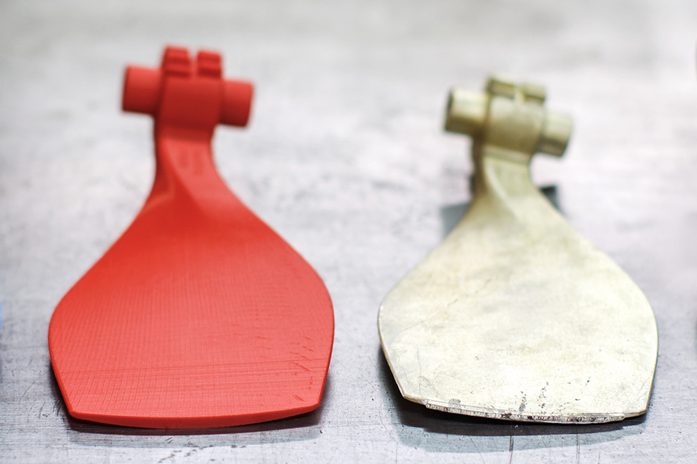
Fig. 2 : 3D printed molds in aluminum frames.
METHOD
Both clear and high temperature resins can be used to print small functional forms, with high temperature resins offering compatibility with a wider temperature range of
thermoplastic melts. Formlabs Clear Resin was chosen for its strength, high detail and smooth surface Clear Resin is preferred for its transparency as you can easily see when forms are being filled, but any of the standard Formlabs Resins (clear, white, black and grey) can also be used as they have similar mechanical properties. The plates were printed with a layer height of 100 µm and took approximately 5 hours per plate. Depending on the geometry, multiple shapes can be printed at once on the build platform to improve printing efficiency.
Fig. 3 : Printing setup in PreForm with cavities up.
Two forms were printed from transparent resin. Parts and subsequent molds were designed to match Galomb machine vise sizes, 1 in3 injection cylinder capacity, and Form 2 build volume.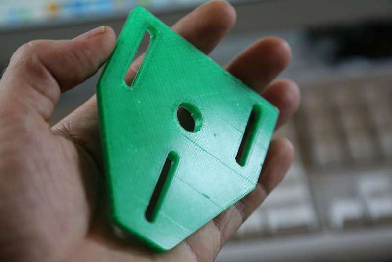 supports were polished.
The parts were then cured for one hour under a 405 nm UV lamp to achieve full mechanical strength and rigidity. For a better understanding of the impact of post-curing on parts, see the Formlabs UV post-curing booklet.
Fig. 4 : 3D printed molds in aluminum frames and die-cast parts.
The first was a large Formlabs butterfly logo and the second was four small Formlabs butterfly logos. Both molds had a cavity, narrow inlets, and sprue at the point of injection and were designed in Solidworks. The molds were inserted into aluminum frames to provide protection from the downward pressure and heating of the injection nozzle. Aluminum frames can also prevent the shape from deforming after repeated use. The frames shown in figures 2 and 4 were custom made by Whittaker Engineering in Scotland, but standard aluminum frames are readily available on request from injection molding machine manufacturers.
Plastic pellets can be purchased online or from suppliers such as IASCO-TESCO. To create different colors, the molten plastic was pre-mixed with powdered dyes prior to injection.
Using a Model-B100 benchtop injection molding machine, Galomb tested printing plates with 25 shots of LDPE. LDPE melts at approximately 325°F (163°C) and was chosen for its low melting point. Of note, Formlabs Clear Resin has an HDT at 0.45 MPa 73.1 ºC after post-cure (see Material Data Sheet). HDT is a measure of the thermal properties of a material, but does not rule it out for use, although LDPE has a higher melt temperature. Whether your 3D printed mold will withstand the injection molding process depends on the melt temperature of the injection material, part geometry, and cooling and cycle times.
RESULTS FOR CLEAR POLYMER
After 25 injections of LDPE, there was no noticeable deterioration in the surface of the molds (chips, cracks or scratches). LDPE is not prone to sticking to polymer molds when tested, but other plastics may require the use of a mold remover to assist in part removal.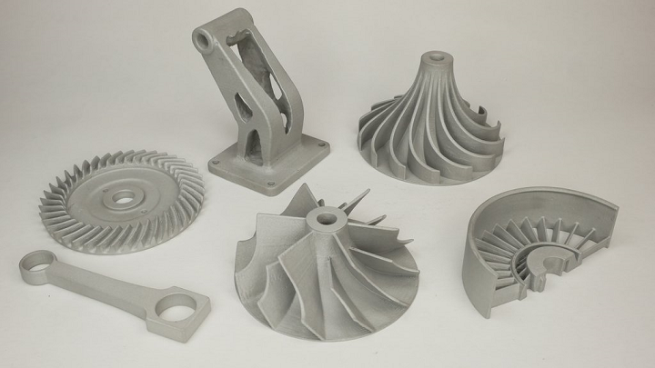 Adhesion of the part to the mold can cause mold wear during ejection. Release agent is widely available, and silicone release agent is compatible with Formlabs standard and high temperature resins.
The cycle time for each injection was approximately three minutes. This process was accelerated by using compressed air to cool the mold. Cyclic injection into forms printed on the Form 2 causes the form to heat up. To counteract this, the cooling time between open mold cycles must be increased. While the mold cannot deform, too much residual heat will reduce molding success if the mold is opened too early. Galomb also improved molding success by etching shallow (0.05 mm deep) vent holes (not shown) leading from cavity edge to mold edge so that air does not enter the cavity during injection.
Some of the injections showed a leak in the parting line due to deformation of the polymer mold during the cooling phase after several injections. Increasing the clamping force in the vise can help mitigate leakage, as can polishing the parting plane of the mold to make it as flat as possible. Galomb proposed incorporating channels into the mold design to include metal tubes and fill them with aluminum epoxy, as a strategy to strengthen the mold, reduce warping, and improve cooling time.
Fig. 5 : A range of injection molding parts made using 3D printed molds.
FURTHER TESTING WITH HIGH TEMPERATURE POLYMER
Clear resin molds have been successfully tested using LDPE, which has a relatively low melt temperature. Higher melt temperatures can cause thermal shock in clear resin printed parts, which manifests itself as a deformed mold surface.
Transparent resin molds experience thermal shock when exposed to higher temperature molten plastic.
Formlabs printed the shape of a USB device case in High Temp Resin to test
| Melting Point | Plastics | High Temp Polymer (HDT at 0.45 MPa = 289° C) | Clear Resin (HDT at 0. | 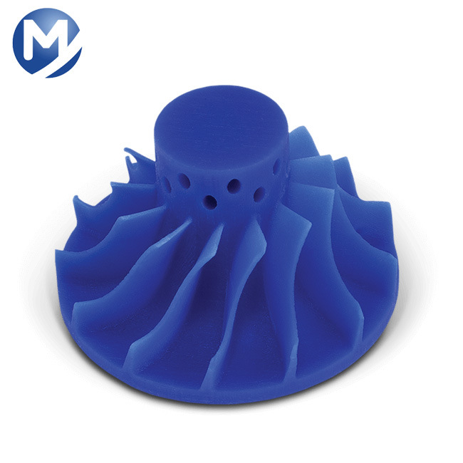 45 MPa = 73.1°C) 45 MPa = 73.1°C) |
| LDPE | 163 °C | ||
| PP | 177 °C | ||
| TPE | 177 °C | ||
| PLA | 180 °C | ||
| ABS | 204 °C | ||
| HDPE | 204 °C | ||
| EVA | 204 °C | ||
| Polystyrene | 226 °C |
High temperature polymer molds showed no temperature degradation at the mold surface for any of the tested plastics.
*DURABLE RESIN polymer is under development and final specifications are subject to change.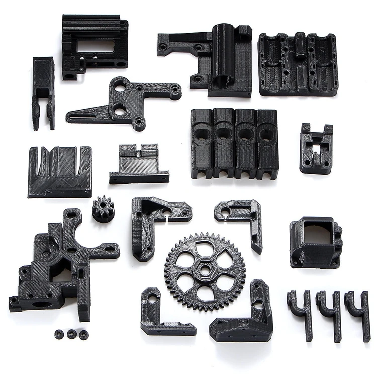
High Temp and Standard are the polymers best suited for molding. Of the Formlabs resins, High Temp has the highest HDT at 0.45 MPa and low thermal expansion. It is also the stiffest material with the highest stretch factor.
The relatively high stiffness of High Temp Resin means that the mold will not deform when the part is removed. This makes the use of a release agent especially important for removing parts molded from rigid plastics such as polystyrene.
GENERAL TROUBLESHOOTING
Form overflow leak.
Leakage occurs when the injected plastic is forced out between the two mold halves. This can happen when the shape is overflowing, or if the split plane is not completely flat. Adding thin exit ports to the mold can help mitigate leakage from overpressure within the mold, facilitate part removal, and eliminate entrapped air that can cause bubbles in the molded part. Although not shown, the plates were tested without the aluminum frame. The downside to this approach is that these parts use more material, which increases printing cost and time, and the forms can be more prone to warping. With this method, a steel washer placed between the printing plate and the nozzle of the injection molding machine protects the print from direct contact and helps distribute forces. In addition, pre-sealing the injection molding cylinder against a metal block helps ensure there are no air pockets to disrupt the plastic flow.
Printed lines visible on some parts; this can be reduced by printing the form with a lower layer height. The plates used in this study were printed at 100 µm, but 50 or 25 µm could also be used. This will improve the cleanliness of the plate surface, but increase print time and reduce tank life.
Final USB device case molded from high temperature resin.
DESIGN INSTRUCTIONS.
When designing a form, consider what will print successfully and what will form successfully.
- Adding one to three degrees of recess on surfaces perpendicular to the direction of the recess will allow easier part removal and minimize mold degradation. Fillets should be applied to the inside edges to reduce buckling from internal plastic stress and facilitate removal of the part.
- Embossed and engraved parts must be offset from the surface by at least 1 mm.
- If you plan on using an aluminum frame, The surfaces of the split planes can be polished with fine sandpaper to reduce flare. add an extra 12mm thick plate to the back of the mold plate to account for compressive forces and ensure complete sealing.
- Be sure to orient the mold halves in the PreForm so that the cavity is facing up. This will prevent reference marks inside the cavity and make post-print processing easier.
90° angle
2° recess
Optimum condition 2° recess and rounding.
PROCESS SUMMARY
STEP 1:
Part design in CAD.
STEP 2
Mold design in CAD.
STEP 3
3D print the forms on Form 2.
STEP 4
Remove support material from molds.
STEP 5
Insert the plastic into the mould.
STEP 6
Remove the part from the mold.
How to recognize 3D printing investment casting?
Compared with traditional investment casting technology, 3D printing of investment casting saves human resources and time, and can create more complex casting patterns. As such, 3D printed casting patterns are increasingly becoming the investment casting solution of choice for foundries and professional engineers. In addition to providing better surface quality and precision, 3D printed investment casting also ensures high quality and consistency in the production of low volume casting components. So how do we understand 3D printing investment casting? We can learn some facts from its benefits and applications.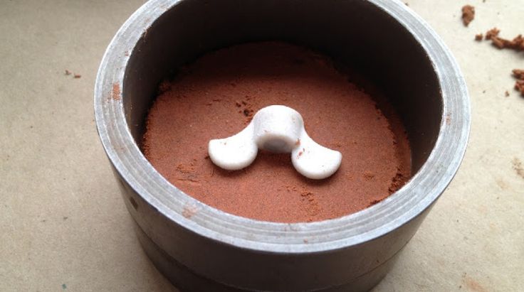
Benefits of using 3D printing for investment casting
For a long time, the focus on investment casting with 3D printing has dominated investment casting. He doesn't need to spend a lot of time and money creating models because he uses CAD files for prototyping. Use sla investment casting technology to directly print the model with extremely low cost and high speed.
First, 3D printed investment casting reduces the number of assembly parts and allows for lighter castings. Strength and durability surpass even traditional metal parts. Be aware that investment casting takes a long time to design and manufacture wax molds.
Secondly, using 3D printing for investment casting to print large-sized parts is an ideal choice. Because it can work at the same time, there is no need to use the small device to print twice as usual. Significantly reduces not only the production time of the model, but also significantly reduced labor costs. In other words, the fewer parts, the less gluing is required.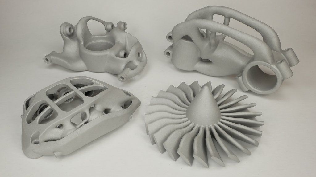
Finally, 3D printed investment casting technology has a higher fault tolerance. Typically, the traditional process of making lost wax takes weeks or months to change the wax shape. And if something goes wrong while building a prototype, 3D printed investment casting will only take a few days to reverse engineer. This situation also applies when a component does not meet the expected standard.
Therefore, 3D printed investment casting is far superior to traditional investment casting in terms of time, cost and ease of use. Adding 3D printed investment casting to your engineering work should be the best choice to grow your business more vigorously!
3d printed metal casting models
The traditional method of investment casting is to use an injection molding process to make wax molds. The cost is about $10,000 and the delivery time is about two months. The disadvantage of this approach is that the foundry cannot produce any prototype castings before the injection mold is made.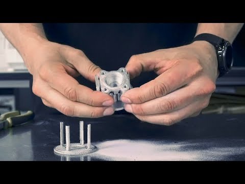 This significantly increases the time spent on the production of components.
And investment casting sla uses FDM technology to create 3D printed casting models to solve this problem. Because foundries can directly print metal casting patterns without waiting. As an alternative to traditional investment casting, 3D printed investment casting is highly efficient and economical. Thanks to investment casting technology in the foundry, it takes only one day to make a model. We can also use it as a prototype to evaluate the shape of a part that perfectly matches the casting produced.
In addition, the 3D printed casting models are very durable and difficult to accidentally damage during transport. You can also put it in a component for testing when you put it into production. The important point is that 3D printed casting patterns printed by sla investment casting have high flexibility. So you can print complex or simple 3D metal casting models according to the actual situation. And your expenses will not increase.
8 steps investment casting process with 3D printing
3D printed casting models are a direct replacement for traditional casting models, but 3D printing wax investment casting does not melt like wax molds. When making metal parts, the 3D printing wax for investment casting will burn in the cavity and leave a small amount of ash. Therefore, we need to remove it when cleaning the shell cavity. When using 3D printed casting patterns to make ceramic cases, vent holes are usually added to the surface. This contributes to the calcination of the 3D printed investment casting. In addition, to prevent casting defects, 3D printed casting models must have excellent surface finish and tight tolerances. Let's see what is the process of investment casting 3D printing?
In this case, we have broken down 3D investment casting into eight simple steps.
Step 1:
Select the configuration file in the printer and click Print. In addition, there are a few things to note: First, when placing the model on the board, choose a direction that requires as little support as possible. Second, use as few fillers and shells as possible. Finally, there must be a certain compensation factor between the 3D printed models of castings and real metal castings. The best value is between 1.007-1.030.
Step 2:
Before we can 3D print the investment casting, we need to make sure that the print surface is smooth, free of defects and debris. At this stage, we recommend two post-treatment methods: spray polishing and dipping.
Step 3:
First lay the part horizontally on the cup, then connect the part and the cup with a wax stick or sprue. This is done to ensure that the liquid metal enters the parts accurately and smoothly. In addition, we must minimize the curvature of the circulation channels. Otherwise, it will impede the fluid flow rate. It is best to place smaller wax blocks in weak spots to achieve an even flow. If there are any holes or gaps, we can use small incisions to fix them.
Step 4:
Dip the wood of the pieces into the ceramic mortar to create the shape. Pay attention to repeated alternation so that the liquid completely and evenly covers the parts. We recommend applying at least five coats. For 3d printed castings with more complex structure, we need to apply about eight layers. Please note that the coating is completely dry before repeating the work. Eventually, the printed material will evaporate during the firing process, resulting in a ceramic shell being used as a casting.
Step 5 :
Put the ceramic coated parts into the furnace. We usually use firing at 1100-1200°C for 40-60 minutes. The time has not been determined. It depends on the type of metal and furnace. After the printed material has burned inside, allow the ceramic shell to cool completely.
Step 6:
Check the shell.