3D printing for foundry patterns
3D Printing & Foundries | Investment Casting Patterns | Stratasys Direct
- March 13, 2018
Industry Highlight: 3D Printing and Foundries
Metal casting at foundries is one of many tried and true manufacturing processes that have been impacted by 3D printing. Stratasys Direct Manufacturing has for more than 20 years worked to introduce the benefits of 3D printing to numerous foundries in the United States and Canada. This experience has led us to develop proprietary build styles and processes for superior 3D printed investment casting patterns and other important production applications such as custom tools and manufacturing aids.3D Printing Investment Casting Patterns
3D printing offers an effective tool-less solution for investment casting patterns with Stereolithography (SL). As an alternative to wax and wood, SL builds patterns with a UV laser that cures and solidifies thin layers of resin. Stratasys Direct builds SL investment casting patterns in a nearly hollow structure with a sparse internal lattice structure and thin walls. This proprietary build style translates to proportionately less ash and minimized thermal expansion forces during flash firing.
Stratasys Direct utilizes two Stereolithography materials for investment casting patterns. SC 1000P is a custom photopolymer formulation developed for low cost investment casting patterns. SC 1000P has low water absorption, and patterns built with this material are less prone to dimensional distortion. SOMOS® Element is a newer antimony-free formulation for investment casting patterns. This material is specifically used when a project calls for casting with reactive metal alloys where antimony may contaminate the cast metallurgical properties.
Stereolithography offers a new design freedom, unbound to tooling. Designs can be easily altered and gating systems can be proven out prior to tooling. SL delivers excellent pattern accuracy and repeatability, at less expense than conventional methods. These benefits translate to higher yields in the casting process and makes the piece easier to ship and more durable in-transit than a wax pattern.
Expertise in Action
Each foundry is unique, which is why we tailor the process and product for each customer’s distinctive operations. We work to fit into each customer’s unique operations by utilizing a successful process. We start by associating each project with lot sizes, materials, as-cast shrink compensation, surface roughness and dimensional requirements to ensure on-time delivery of quality patterns.
Then, printing parameters are customized to each pattern’s geometry and cast metal alloy. The patterns are optimized with low CTE, print time and material usage. Stratasys Direct has significant experience seamlessly bonding and assembling large SL patterns. Projects more than seven feet in diameter have been assembled with custom assembly fixtures and expertly delivered in large part packaging. We apply specific surface finishes to parts in order to work with foundry-specific face coats. Our sophisticated leak testing device checks each pattern for a perfect seal, and we offer vacuum ports and testing equipment for quality control at the foundry.
Custom Tools for Foundry Functions
Stratasys Direct offers a host of advanced manufacturing solutions for developing manufacturing tools and aids for foundry customers including hybrid wax setters, wax pattern assembly jigs, straightening fixtures, pattern and core inspection gauges, sand casting patterns, match-plates and core-boxes.
Our engineers are experts in examining a customer’s unique operations and identifying areas that custom jigs, fixtures and other manufacturing aids could transform your production floor.
Even with a centuries old manufacturing process, 3D printing can widen foundries customer base by offering a compatible processes and custom tools.
3D Printed Sand Casting Patterns
Name *
First
Last
Professional Email *
Phone *
Organization *
Industry *AerospaceAgricultureArchitectureArts Design and CreativeAutomotive and MotorcyclesChemicalConstructionConsultancyConsumer ElectronicsConsumer ProductsEducation and ResearchEnergyEntertainment and AdvertisingGovernment / Not for ProfitIndustrial Components and ToolingIndustrial Equipment and MachineryMarine/Ship ConstructionMedical and DentalMetal & Steel IndustryMilitaryOther/Serving different industriesPattern Making Molding and CastingPipes and IronworkingPlasticsPrint/Scan/Engineering Service BureauRenewable EnvironmentResellerRetailRoboticsTelecommunicationsTransportation
Location *United StatesCanadaGermanyFranceUnited KingdomItalySpainChinaAndorraUnited Arab EmiratesAfghanistanAntigua and BarbudaAnguillaAlbaniaArmeniaAngolaAntarcticaArgentinaAustriaAustraliaArubaAland IslandsAzerbaijanBosnia and HerzegovinaBarbadosBangladeshBelgiumBurkina FasoBulgariaBahrainBurundiBeninSaint BarthélemyBermudaBrunei DarussalamBolivia, Plurinational State ofBonaire, Sint Eustatius and SabaBrazilBahamasBhutanBouvet IslandBotswanaBelarusBelizeCanadaCocos (Keeling) IslandsCongo, the Democratic Republic of theCentral African RepublicCongoSwitzerlandCote d’IvoireCook IslandsChileCameroonChinaColombiaCosta RicaCubaCape VerdeCuraçaoChristmas IslandCyprusCzech RepublicGermanyDjiboutiDenmarkDominicaDominican RepublicAlgeriaEcuadorEstoniaEgyptWestern SaharaEritreaSpainEthiopiaFinlandFijiFalkland Islands (Malvinas)Faroe IslandsFranceGabonUnited KingdomGrenadaGeorgiaFrench GuianaGuernseyGhanaGibraltarGreenlandGambiaGuineaGuadeloupeEquatorial GuineaGreeceSouth Georgia and the South Sandwich IslandsGuatemalaGuinea-BissauGuyanaHeard Island and McDonald IslandsHondurasCroatiaHaitiHungaryIndonesiaIrelandIsraelIsle of ManIndiaBritish Indian Ocean TerritoryIraqIran, Islamic Republic ofIcelandItalyJerseyJamaicaJordanJapanKenyaKyrgyzstanCambodiaKiribatiComorosSaint Kitts and NevisKorea, Democratic People’s Republic ofKorea, Republic ofKuwaitCayman IslandsKazakhstanLao People’s Democratic RepublicLebanonSaint LuciaLiechtensteinSri LankaLiberiaLesothoLithuaniaLuxembourgLatviaLibyan Arab JamahiriyaMoroccoMonacoMoldova, Republic ofMontenegroSaint Martin (French part)MadagascarMacedonia, the former Yugoslav Republic ofMaliMyanmarMongoliaMacaoMartiniqueMauritaniaMontserratMaltaMauritiusMaldivesMalawiMexicoMalaysiaMozambiqueNamibiaNew CaledoniaNigerNorfolk IslandNigeriaNicaraguaNetherlandsNorwayNepalNauruNiueNew ZealandOmanPanamaPeruFrench PolynesiaPapua New GuineaPhilippinesPakistanPolandSaint Pierre and MiquelonPitcairnPalestinePortugalParaguayQatarReunionRomaniaSerbiaRussian FederationRwandaSaudi ArabiaSolomon IslandsSeychellesSudanSwedenSingaporeSaint Helena, Ascension and Tristan da CunhaSloveniaSvalbard and Jan MayenSlovakiaSierra LeoneSan MarinoSenegalSomaliaSurinameSouth SudanSao Tome and PrincipeEl SalvadorSint Maarten (Dutch part)Syrian Arab RepublicSwazilandTurks and Caicos IslandsChadFrench Southern TerritoriesTogoThailandTajikistanTokelauTimor-LesteTurkmenistanTunisiaTongaTurkeyTrinidad and TobagoTuvaluTaiwanTanzania, United Republic ofUkraineUgandaUnited StatesUruguayUzbekistanHoly See (Vatican City State)Saint Vincent and the GrenadinesVenezuela, Bolivarian Republic ofVirgin Islands, BritishVietnamVanuatuWallis and FutunaSamoaYemenMayotteSouth AfricaZambiaZimbabwe
Subscribe to our Newsletter
- and receive news about 3D printing
Terms of Service *
- I have read and agree to the Terms of Service
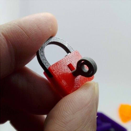
We create a pattern model for printing from plastic
SiniyPu
The master class was created based on the materials of Ira Bortnik, in which she talks in great detail about creating a mating pattern with her own hands. The acquired knowledge was useful to me: I created a template for myself and used it repeatedly. But over time, the paper was worn out, the question arose of increasing its service life. I wanted to make a pattern from a more durable material. And I decided to create a model using the appropriate software, and then print it on a 3d printer (fortunately, many companies have appeared that deal with this).
I will build a 3d model of a pattern with symmetrical curves. By the same principle, you can build any other.
Construction will be carried out using a 3D modeling program. It is “closer” and more convenient for me to work in KOMPAS (anticipating questions about why this particular software was chosen).
So, our goal is to build a 3d model of the mating pattern using the 3D modeling system.
First, we will create a sketch (the basis of the part), and then using the extrusion operation we will get a three-dimensional model.
1. Run the program.
2. In the menu, select File --> New... --> Detail .
3. Select View --> Orientation --> XYZ Isometric from the menu (or you can click the Orientation button on the toolbar View and select XYZ Isometric ).
4. On the left is the model tree. Expand it (click on the plus near Origin ) --> select the ZX plane
This is the plane in which we will draw the sketch, most often, this is the ZX plane - horizontal.
5. Now we will build the base of our part, that is, the sketch.
1) At the top of the toolbar, press the button Sketch .
2) We build a rectangle (the dimensions of our pattern are 14 cm x 9 cm):
- on the left of the toolbar, press the button Geometry . Below we press the button Rectangle ;
- Properties panel appears at the bottom of the window. Dimensions are indicated in millimeters. In field Height enter 90 and press Enter , in the field Width - 140 and Enter ;
- click on the sheet;
- press the button STOP on the Property bar to interrupt the execution of the command.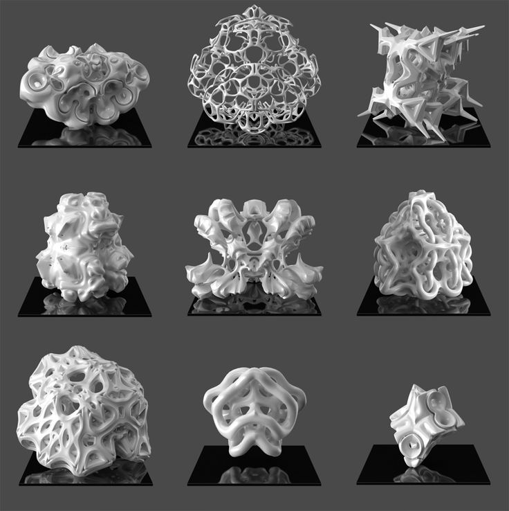
The rectangle is built.
3) We make roundings (we will have radii: 1.5 cm, 2.5 cm, 3.5 cm, 4.5 cm).
- on the toolbar Geometry press the button Rounding ;
- at the bottom of Property bar set the radius of the first rounding in millimeters, for example, 15 and press Enter ;
- click successively on the two sides where the fillet should be.
The first fillet has been created.
- at the bottom of Property bar set the radius of the second rounding in millimeters, for example, 25 and press Enter ;
- click successively on the two sides where the fillet should be.
Second rounding completed.
- similarly build the rest of the fillets.
- after building all the fillets, press the button STOP on the Property bar to interrupt the command execution.
The fillets have been created.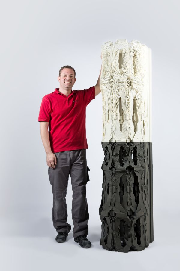
4) Exit the Sketch mode (at the top on the toolbar, press the button Sketch ).
6. Building a three-dimensional model:
- on the left of the toolbar, press the button Edit part . Below we press the button Extrusion operation ;
- at the bottom on Property bar select Direct direction , To distance , set the distance 2 (this is the thickness of the pattern in millimeters). To confirm, press the button Create object (or Ctrl + Enter ).
You can also sign the radii on the plate itself, I'll tell you about it another time.
7. Save the file: File --> Save --> specify the name and location of the file.
8. For most 3d modeling programs, the format STL is used. Therefore, select File --> Save as ... --> specify the file type STL ; the name and location of the file.
The file is ready to print on most 3d printers.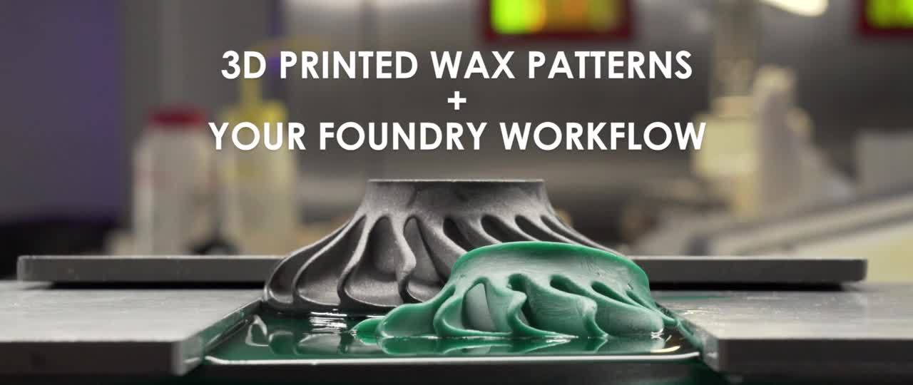
P.S.: I recommend that you clarify the file format in advance where you are going to print the 3d model.
But it's better to see once...
Always with you, Elena Siniypu
Rating
★
★
★
★
★
5.0 (1 vote) Blog (2) Keywords
Lice -flooding
Cooking
Dolls and toys
Model
Materials for creativity
DIY furniture
miniature
DIY shoes
Organization of space
Pyroit
Work work
Work work with beads
Working with metal
Working with fur
Working with glass
Restoration
Painting
DIY candles
Scrapbooking
Carpentry
DIY bags
Weaving
DIY packaging
Floristry
Photography and video
Artistic carving
Sewing
3D printing molds
3D printing moldsShare with friends
Printing forms according to the 3D model of the customer's form
Files of prt, stp, step, x_t format are accepted for printing.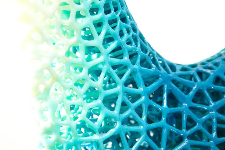
The formats igs, iges, x_b, stl are also possible.
All files pass input check for correctness for printing.
If it is not possible to correct it on our own, we send the customer requests for correction.
Our technologist checks the correctness of the customer's injection system and, if necessary, makes recommendations for adjustment.
To take them into account or not is the responsibility of the customer.
If necessary, we ourselves will develop a mold model and injection system, we will carry out mathematical modeling of mold filling. More about 3D sand mold modeling:
3D modeling of sand molds
Features of the production of 3D sand molds
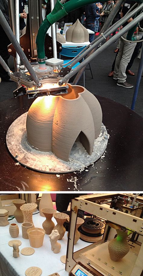
3D sand mold manufacturing (PCM - Patternless Casting Manufacturing) is one of the most advanced casting technology at present, which combines traditional sand casting technology and 3D printing.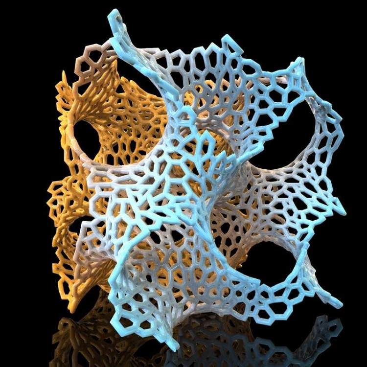 This technology allows you to quickly create sand molds and cores that are effective for quickly casting complex parts. PCM does not need a template and can reduce production cycle and cost.
The first step of is to create a mold model with a casting system from the part model and convert the mold model to stl or prt format. When designing a model, it is possible to easily ensure the presence of stamps and logos of any kind on the casting, as well as pinholes and bulges on the mold, ensuring guaranteed gas permeability without loss of strength. The print resolution allows you to print elements as small as 3 mm. Then, using TOP 3DP's own software, the virtual form image is placed in the virtual print volume. If necessary and if there is free space, it is possible to place several identical copies of forms or several different forms \ cores for simultaneous printing.
The next step TOP 3DP "cuts" the stl model of the casting mold into layers 0. 3 or 0.5 mm thick (depending on the required casting accuracy) and receives geometric information to form cross-sectional layers. These sections of the section are then sequentially "printed" on layers of sand, thereby creating a three-dimensional shape.
During printing, the catalyst and sand are evenly mixed, then a thin layer (0.3 or 0.5 mm) is placed on the platform. The array of nozzles accurately sprays the binder onto the bed following the geometric information of the cross section. The curing reaction takes place between the catalyst and the binder. This is repeated layer by layer until the object is built. Uncured sand in powder form is easily removed. After the excess sand is removed, the mold is ready and can be used for metal casting.
Stages of work:
Key Benefits of the Technology
Casting parts of any shape can be made
Especially parts with complex and curved surfaces
Casting can be built in one cycle
Which reduces design constraints and machining
Suitable for making a variety of complex metal components and molds
Replaces pattern making
Can be used to cast tooling for serial casting
Speed and cost of tooling preparation are drastically reduced
Suitable for castings from various non-ferrous and ferrous metals
Non-ferrous metals (Al alloys, Cu alloys, etc.