Internship 3d printing
Students in 3D printing – get started now at EOS
Do your studies focus on technology, science or economics, and you know enough not to fill the 3D printer with paper? Are you interested in completing an internship in parallel to your university studies, or choosing a thesis topic with practical relevance? Then welcome to EOS, the world’s leading technology provider in the field of industrial 3D printing of metals and plastics.
We are a hidden champion with lots to offer. Because our technology creates added value for all of us. From new opportunities in sectors ranging from medical technology to aviation – the prospects are essentially limitless. Become part of our world by inquiring about our offers for students.
53_individual_productionAt EOS, you already take over responsibilities as a student. Bring in your ideas and work together with our experts to shape the future of industrial 3D printing.
At EOS, you can expect attractive remuneration from 15-17 €/h as working student and 900-1.000 €/month for your internship.
60_resp_peopleEnthusiasm for our technology, the flair of an international family business, a diverse culture and short decision-making paths – these are just a few of the things that will mark your everyday life with us.
16_knowhowWe offer you home office options and flexibility in your daily work so that your studies don't miss out. Alternatively, a travel allowance during your internship.
33_purityOur company restaurant offers diverse, healthy and delicious dishes with an enjoyable atmosphere.
02_location_aOur headquarters are located at the Krailling Innovation Mile (KIM) in Krailling near Munich. You can easily reach us from Munich city center by taking the S6 to Planegg. From there, Bus 906 will drop you off right at our front door.
Think, Feel and Experience EOS in 3D and Shape Your Professional Future in Additive Manufacturing with Us.
see all our open positions
“The working atmosphere at EOS is awesome. Everyone is on friendly terms with everyone else and you’re quickly integrated into the team. And exchanges between students are encouraged. I was exposed to many different points of view about industrial 3D printing. My job was to check our metal and polymer materials with several different measuring methods. These methods were taught to me by EOS and were the perfect addition to the theoretical knowledge from university. I’m also learning lots about properties and the requirements expected by customers in today’s world. Other positive aspects about EOS include fair pay, flexible working hours and a variety of opportunities for working while studying.”
Maria | Working Student
Prerequisites for Working Students at EOS
- Enrollment in a technical, scientific or economic course
- Enthusiasm for 3D printing and fun bringing cool technology to the next level
- Initiative for developing creative solutions and ideas
- Very good German and English language skills
Facts About Working as a Student
- At least six months of employment (longer is welcome)
- Max.
 20 hours per week during lecture periods
 - Fair compensation for your contributions
- Already take on responsibility during your studies
- Small projects will be entrusted to you and supervised by buddies from technical departments
back to overview
“Why might a student want to work at EOS? That’s easy: fascinating technology, impressive 3D-printed components, a good atmosphere, great support for students, diverse opportunities and tasks with plenty of responsibility. I’m currently working in data control, which is a great fit for my studies. I can put what I learn at university into practice, and vice versa. It also motivates me to know that my work will help my colleagues in the long term. For example, I helped to modernize maintenance work and create checklists in quality management. As a student, you’re integrated quickly and always feel like part of the team. I would definitely recommend any student to apply to EOS.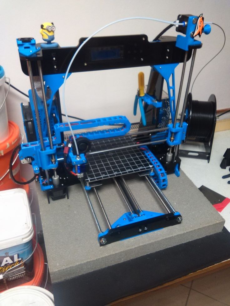 ”
”
Johannes | Intern and Working Student
Prerequisites for an Internship at EOS
- Enrollment in a technical, scientific or economic course, or alternatively between two courses
- Enthusiasm for 3D printing and fun bringing cool technology to the next level
- You should be prepared to already begin taking on responsibilities during your study and to contribute your own ideas
Facts About Internships
- At least three months duration (longer is welcome)
- Full-time, 40 hours per week
- Fair compensation for your contributions
back to overview
"Additive manufacturing and the increasing degree of automation in the industry have fascinated me from the very beginning. A student position at EOS seemed completely logical. I wanted to experience industrial development processes, learn from experienced colleagues and help shape the further development of the technology. After working in parallel to my studies, I applied for a practical thesis directly in development. Together with my supervisor, I became an expert and driver of the topic - you have to be ready for all the responsibility. In addition to the positive working atmosphere and great colleagues, it cemented my passion and convinced me to join EOS permanently.”
Tom, thesis in the field of “Predictive maintenance”
Prerequisites for a Thesis
- Enrollment in a technical, scientific or economic course
- Prior internship at EOS to become familiar with our technology
- Enthusiasm for cool technology and fun working on your final thesis together with us
Facts About Thesis
- The thesis is full-time and the duration depends on examination regulations
- The topic is coordinated between you, the university and EOS
- Reimbursement for completing your thesis
back to overview
“After university, I was looking for a way to expand my know-how in laser sintering.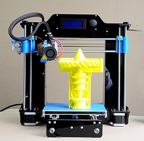 It wasn’t long before I found EOS, given that they stand at the intersection of 30 years of experience, market leadership and global networking. Now, as part of my PhD thesis, I’m working on ways to test the suitability of polymer powder for 3D printing in the laboratory. This will save iterations, time and costs. I can focus on basic research because I’m not tied down by everyday project work. But I can ask my team questions whenever I need to and my supervisor takes excellent care of me.”
Jens | PhD Student
Prerequisites for a Successful Application
- Student with an advanced degree (master’s)
- Interest in an industrially focused doctorate and the subject area of additive manufacturing
- Experience with independent scientific work
- Practical experience from internships or student work
- Experience abroad from studies and/or internships is desirable
- Very good written and spoken German and English language skills
Facts About the PhD Program
As a PHD@EOS, you’ll be directly employed by EOS and you’ll sign a 3-year employment contract.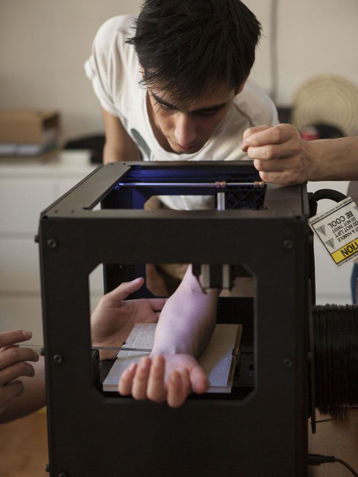 You’ll work on a research project relevant to EOS four days a week and you’ll be directly integrated into a team from R&D. The topic of your PhD thesis and your research question will of course be mutually coordinated.
If you already have a supervising professor in mind – great! If not, we can suggest suitable contacts through our research partnerships.
back to overview
Students at EOS Christmas Party
Outside at the EOS Summer Party
Students at the EOS Summer Party
01
02
03
04
05
06
07
08
09
10
Supporting young talent is important to us.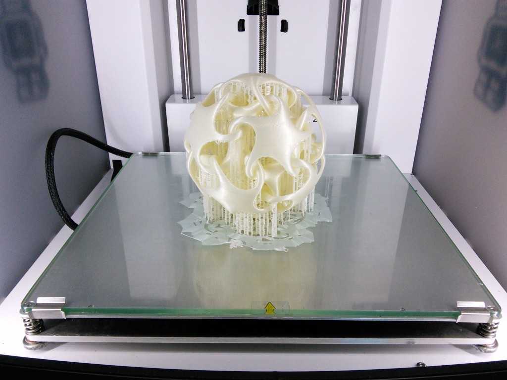 We are constantly expanding our network of national and international universities and institutes.
For example, we helped the Munich University of Applied Sciences to set up a new rapid prototyping and manufacturing laboratory. The RPM-LAB is primarily intended for teaching and can be used for research and development projects.
We’re also gladly available for courses or one-time university events to allow students to get to know EOS and our technology.
Contact us or read through our FAQs for applicants – you might find that your question has already been answered.
Interested to keep in touch?
Follow us on LinkedIn and be always up to date.
Please note: to simplify the language and without any intention to discriminate, we only use male pronouns. This is intended to include all genders.
internships – re:3D | Life-Sized Affordable 3D Printing
Intern Jacob Lehmann shares on his recent DIY solution to personalize his aging Beetle.
My 3D printed Superman Hood Emblem
By: Jacob Lehmann
I work at re:3D and my job is to figure out and test cool and unique ways to use our 3d printers. I have 2003 VW beetle (and I love it) but some of the aesthetics have been worn and aged poorly over the years. So I had the idea to custom print a rear hood ornament. My amazing bosses thought this was a great idea and helped me to design and realize this idea.
It was hard to pick what exactly I wanted to make for my car. After running through tons of ideas I finally decided that because of the deep sienna blue of my vehicle that a superman logo would look amazing on it. This is a picture of my car after I peeled off the old rusty and broken VW emblem.
Previous
Next
First I designed the hood emblem in a free Cad software called Onshape. You can access the tool at this link: https://www.onshape.com/ if you are interested.
After slicing the file for printing, we put it on the Gigabot and watched it come to life!
Previous
Next
And then we tested it on my car. After looking at it closely, I decided I wasn’t happy with the size and printed a second to fill up the space better.
Before we started we knew that the final solution wasn’t going to be in PLA. In the Texas summer sun, thermoplastics such as PLA warp when left in a car, let alone on the boiling hood. Although this material is perfect for 3d printing because it melts at roughly 190+ Celsius, that very feature makes it hard to use outdoors, inside of engines, or pretty much anywhere that gets hot.
Thankfully our friends at Deep in the Heart Art Foundry (who own some of our Gigabots and use them in their lost wax casting) were more than happy to help us cast an alternative. We originally wanted to cast the piece in bronze and patina it, but they suggested that it would look better and be much lighter to cast it in Stainless steel. You can check out some of their amazing works of art here http://www.deepintheheart.net/. Here is the piece once we got it back (with a little bit of polishing).
And after I finished polishing and sanding the piece.
Here is the finished stainless steel piece next to the smaller PLA prototype.
Now all that was left to do was mount it on my vehicle. After cleaning the surface of my rear hood and the backside of the piece with some alcohol, and removing all the dust and grime, I placed some 3m double-sided tape on my car. NOTE: my bosses were concerned for my and other driver’s safety and have since purchased industrial epoxy.
And finally, the beautiful hood emblem is complete and placed on my car. Now I can drive around fighting DC supervillains as much as I want.
Happy printing!
~Jake
- Twitter: @jacobelehmann
For a long time, my best friend Mason has been bugging me to watch Rooster Teeth’s animated show RWBY. Don’t get me wrong, I love anime, but I was already watching too many shows, and kept putting it off. Then, one day, re:3D’s cosplay enthusiast Rebecca asked if there was some way we could print the Crescent Rose (the instantly recognizable, 6ft tall scythe from RWBY). I immediately said yes, which made me finally binge-watch volumes 1 and 2 of RWBY on Netflix. Much to Mason’s delight, I loved it! I was super excited to make the scythe, not just because of my inner fangirl, but for the creative challenge of creating a 6 foot tall 3 foot wide scythe!
Rebecca and I debated for many hours about how to go about the design for the scythe. As you all might know, the Crescent Rose has the ability to transform into a more compact gun. We discussed the viability of this option ,and ultimately decided that because of the plastic we would be using and the laws of physics, that we should pursue making the best possible scythe-version of the Crescent Rose, and not worry about it transforming.
So, I threw myself into research. I spent many hours pausing the show and sketching, as well as staring at various other interpretations of the scythe on google images. I finally decided on a plan of action, and started modeling the scythe in Onshape, a beta CAD software.
When using a 3d printer, it’s important to keep in mind how your piece is going to be printed. 3D printers start to print from a base layer up, and use supports for overhanging parts. Therefore, I modeled most of the scythe to be easily printed from a flat bottom. Although I could have modeled the piece completely true to the show, I gave up some minor design features so that my prints would be faster and use as little supports as needed. The Gigabot, because of its large print size of 8 cubic feet, allowed me to make the individual pieces much larger and easily create a life sized model of the scythe.
I made the model into 11 different pieces that could be assembled after they were pulled off the printer. I then printed these pieces using PLA on a Gigabot. I used different infills and layers for different pieces, 2-3 layers depending on how much strength I was going to need from that piece and ranged 5-20% infill depending on if I need the piece to be light or not. I usually heat the plastic at around 195-200 degrees Fahrenheit.
When assembling plastic pieces, together keep in mind in order in which you want to paint your piece, and the different bond strength of the glues or tapes you are using. For the Crescent Rose, I mainly used just basic Gorilla Glue super glue. For more stress intensive pieces, I used Gorilla Glue epoxy and clear caulk to give joints a more uniform look.
Previous
Next
After we had finished printing all the pieces, the next step was to remove all the support material. Then, I sanded down and fixed the smaller print errors such as place where there is a slight over-extrusion on corners or small print-shifts. Finally, I started painting! A timelapse of the process is available below.
I used a basic white primer spray paint that sticks to plastic. This created a good base layer on the models that I could paint other layers of spray paints and acrylic on top of.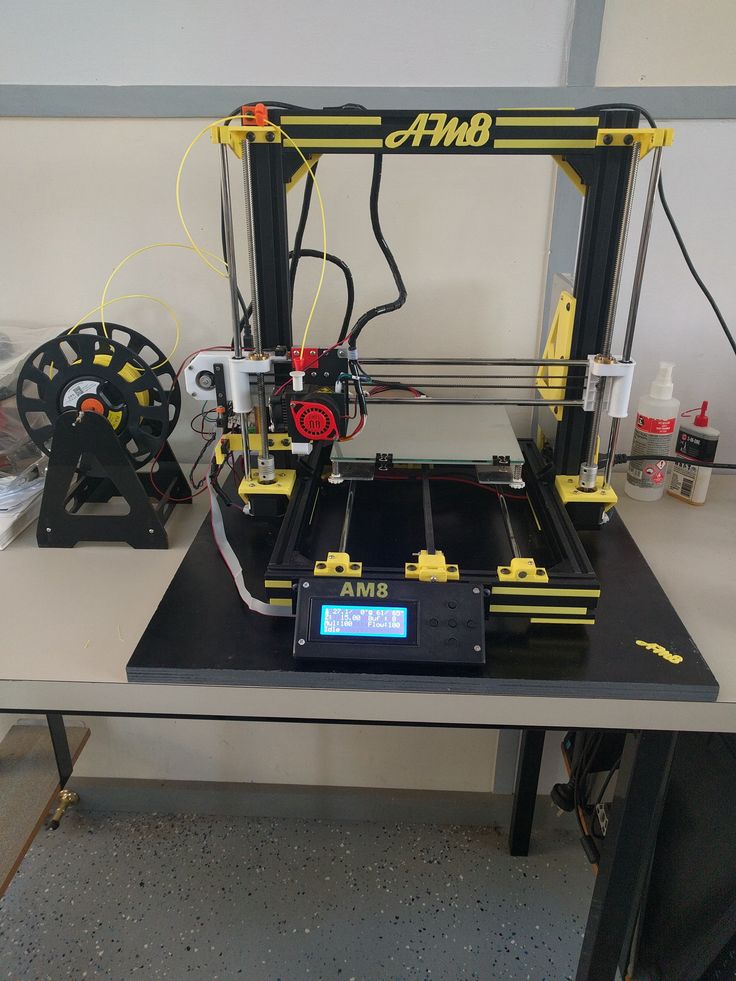 For the majority of the scythe, I used red and chrome spray paints and then used black and red acrylics and a paint brush to finish detailing.
Previous
Next
My Crescent Rose actually ended up being a little too big, finishing at 6’10” tall and 4’4” wide. I had the outstanding luck to get to bring my scythe to the Rooster Teeth offices and, who should happen to walk by but the voice of Ruby, the very character who wields the Crescent Rose– Lindsey Jones!
Everything was not all roses and sunshine though. I had some large problems throughout the course of making this scythe. Some pieces ended up being more fragile than I would have wanted, and broke a few times. The overall size and shape of the scythe creates its own unique problem. Even though the material is fairly lightweight, the scythe acts as a natural lever where the fulcrum is where the staff meets the blade, causing a large amount of pressure and tension right at the joint.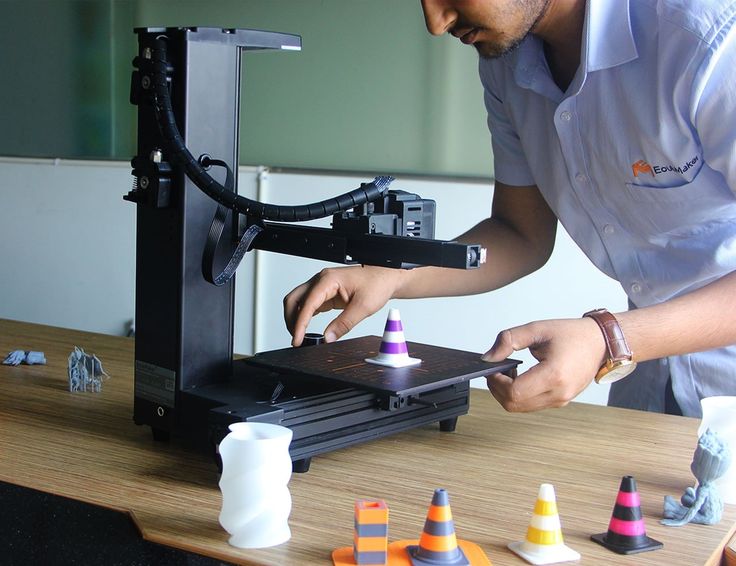 My solution to this problem was more gorilla glue and wooden and metal rods drilled into the plastic and hammered through to help support the weight.
Previous
Next
Another huge problem that occurred during the print of one of the pieces completely failed on us. The head of the Gigabot extruder got clogged 48 hours into the 55 hour print. Fortunately, when a print fails, the print usually has a flat layer at the point of failure. I was able to measure the print, and edit my model accordingly so, so I could print only what was missing. The end result looks just like a filament swap mid-print. I credit the ease of this fix to the great usability of OnShape.
Finally, the last and probably worst problem I ran into was the Texas Summer Sun… This is a problem that is unique to people in the south who use 3D printers. Even though the plastic melts at roughly 200 degrees fahrenheit, your print will warp if left in your car or your backyard too long. This happened on the largest piece of the scythe and caused my really nice print fix to be extremely noticeable. I had to reheat my piece and to try and warp it back to a usable condition– with limited success. I decided at the end that the condition of the piece after I re-warped it was good enough to merit not reprinting 55 hours worth of plastic.
In order to save you some work modeling, I posted the files on Onshape so that you can print RWBY’s Crescent Rose too!
I’m unveiling the files at RTX at the re:3D booth prior to our Panel today (Aug 8th) on 3D printing & cosplay. You can check out the panel at 1pm at the JW Marriott, Room 303.
You can find me on twitter @jacobelehmann or email me at [email protected] to discuss the process in more detail.
Below are the sources I used to help me create my model.
- http://i.ytimg.com/vi/rST5VxiZ_gE/maxresdefault.jpg
- http://goo.gl/9XzVMq
- http://goo.gl/SsO63J
- https://en.wikipedia.
 org/wiki/RWBY
 - http://goo.gl/r6x12t
Thanks for reading!
~Jacob
Pranathi Peri is developing a set of 3D printed, playable musical instruments for her summer internship. In her own words, she describes her design process:
Have you ever wanted to 3D print your own ukulele? Well now uke can! For the second instrument of my 3D printing internship, I decided to design and print a ukulele. After all, who didn’t trawl the internet looking for the best acoustic guitars under 300, and then end up with a ukele anyway because it was cheaper? They have such a charming aesthetic, and it’s that student living nostalgia that I wanted to try and tap back into. It also dramatically simplifies the process of choosing an acoustic guitar for your child, you can just print one instead now. Although, we have to admit, perhaps it won’t have the same charm.
The history of the good ol’ uke goes way back. During the late 1800s they were first introduced as instruments in Hawaii, where its name literally meant “jumping flea. ” Well-known songs like I’m Yours, by Jason Mraz, Riptide, by Vance Joy, and Imagine, by John Lennon have familiar ukulele riffs which have contributed to the popularization of the instrument, yet these bands use the ukulele in maybe one to two of their songs, and then proceed to abandon it.
I know what you’re thinking; why would I want to design such an uncommonly played instrument?
Although the ukulele is not a widely sought-after instrument like the electric guitar, and piano, I decided to design and print it because it combines the aspects of many popular, commercialized instruments. For example, the ukulele is compact, like the violin, but is not as susceptible to external factors that may may warp the acoustics. It retains the same resonance as the acoustic guitar like the Yamaha FGX800c, but within a smaller body. It has strings that can be tuned, just like a piano, but rather than 236 strings, each with their own unique thickness and reverberation, it has 4 which are tuned to C, E, G, and A . For these reasons, and many more, I figured that a ukulele would be relatively easy to design and print, while still containing key aspects of various other basic instruments.
During the process of actually printing the ukulele, I learned many things about designing the instrument itself. One of which being, SAVE YOUR SOLIDWORKS MODELS EVERY 5 MINUTES. There is nothing more traumatic than losing a solidworks file which you had just finished after 1 solid week of work.
However, the portion of this project in which my learning fared most, was the printing, and post-processing of the instrument. Failed prints were rather frequent in the first stages of printing. During our first attempt at printing the body, we decided to orient the body to stand at a 45 degree angle, in order to print it all in one piece. Little did I know that what would be printed would look something like a bird’s nest. Because of some issues with the fan near hot-end of the bot, the print shifted, and proceeded to print midair. Although printing the body in one piece was possible, we decided to go the easier route of printing it in two separate, flat pieces.
Previous
Next
Fast-forwarding to when the ukulele was half-assembled, I stumbled upon some valuable learning experiences. In case you didn’t already know this, GORILLA GLUE SUPER GLUE STICKS VERY WELL. Always use gloves when handling super glue. (I may or may not have learned that the hard way.)
Previous
Next
The fretboard took several prints, but I had already expected this when I was designing the ukulele. In order to get the placement, and height of the frets just right, it would require some trial and error. This is why I made the neck and frets separate pieces in my model. The first fretboard I printed was way too thick, causing the strings to collide with the higher-up frets. This ended up producing not-so-pleasant vibrations. The fret placement was also a little bit off, causing all the notes to be disturbingly sharp.
The second fretboard was more successful, not only because the black filament made the ukulele look more sassy, but because the fretboard was skinnier, (eliminating the unpleasant vibrations) the frets were taller, (facilitating the playability) and the fret placement was shifted, but wasn’t shifted down quite far enough.
Which leads us to the third fretboard–perfection. That wrapped up project uke once and for all–or so I thought.
Previous
Next
My crowning achievement was playing a funky ukuleke riff for the first time. Then I did something very, very, VERY stupid. I left the 100% completed ukulele in the car for no more than 45 minutes, and by the time I came back, the ukulele had completely warped. Because the body of the ukulele was so thin, it had actually folded in on itself, and left the bridge, shattered.
This didn’t upset me though; I thought of it as a way to make improvements to ukulele 2.0, that I had missed in the original. For example, I could combine the frets and neck, to eliminate the number of parts I had to super-glue together. I also had the chance to make an awesome video for the re:3D What NOT to do 101 When 3D Printing You Tube Channel!
However, after exploring this option, I realized with support material the model is still best split with the fretboard separate so I re-printed it just in time for an interview!
Over-all, printing this ukulele definitely gave me more insight into the musical world. Not only did it open up a new door of opportunity for gigabot, but it also taught me the process of trial and error, and that things rarely ever work out the first time. Another interesting thing I learned about the acoustics of the instrument, was that the PLA filament body actually had a stronger, and more vibrant resonance, as opposed to the wooden ukulele.
I hope to use this new knowledge to lead me into my next project–an electric guitar!
References:
- http://www.encyclopedia.com/topic/ukulele.aspx
- http://www.hiloguitars.com/AboutUkuleles.html
- Inspiration: http://www.thingiverse.com/thing:268090
You can find me on:
- Instagram, Twitter: @PranathiPeri
- Facebook: https://www.facebook.com/profile.php?id=100004462757466
Jacob Lehman is exploring 3D printing & cosplay during his summer internship. In his own words, he describes his design process for printing Thor’s Hammer Mjolnir
Are you tired of those pesky frost giants always ruining your day? Well fear no more! With The Thunder God’s Hammer Mjolnir, you will be able to make frost giant toast and butter them to perfection with a few extra bludgeons! Forged in the heart of a dying star or on a 3D printer (I forget which) this Hammer will always be able to tenderize your enemies with shocking ease, but only if you are worthy!
3D modeling in cosplay is great way to create large lightweight and durable props. Because 3D printing can create a shell on the outside and a mesh layer on the inside, the final product ends up being lightweight. This is great for cosplayers that want to carry around weapons that are bigger than their body all day at a convention. This also applies to full bodies of armor. 3D printing can also make higher quality props due to the ability to leverage better in precision of designs and symmetry than hand carvings or paper mache.
The Gigabot, due to its very large bed, is much better suited to printing cosplay props than a regular desktop 3D printer. Larger pieces means that there is less assembly at the end and an overall uniformity to the final model.
When I began the project I decided to make the hammer modular, meaning that it is comprised of multiple pieces that would be assembled at the end. I did this because it allows me to go back and change pieces if I want to and not have to reprint the entire hammer. This is also a good experiment for some of my later projects that will be larger than the 8 cubic feet build volume of the Gigabot. I wanted to practice with different designs as well as different methods of assembly.
My project helps to build upon and intersect with the techniques used by the artistic and inclusive cosplay community. It allows me to document the possibilities of 3D printing and provide alternative methods for creating props and wearables.
I modeled Thor’s Hammer on a Beta CAD software called Onshape. Overall it took me about 8-10 hours to complete the model with various iterations sucking up most of the time. Here are a few of the early models:
Both of these had some obvious flaws that I decided I didn’t like for the final product and I ended up sticking to the Marvel Cinematic Universe Version. The second picture shown above is one of the models where I did a lot of mirroring to save time on making the model and ended up doing a really intricate half of the model. When I mirrored the base it ended up being too long. Here is my final model:
This file was then moved over to another software called Simplify3D where it was formatted for printing.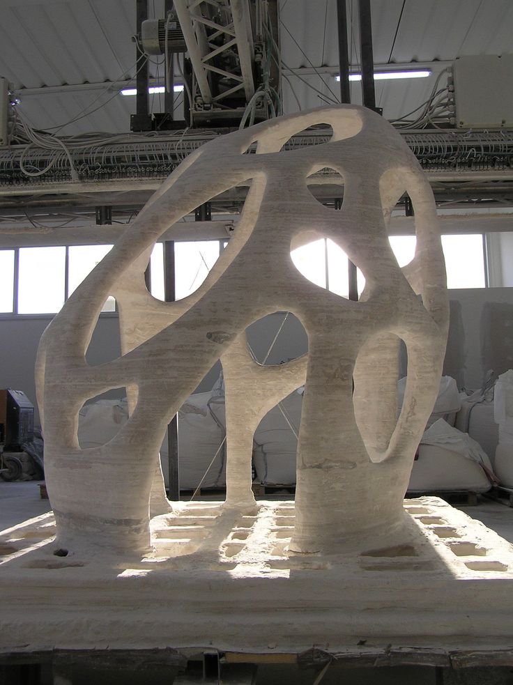 All three pieces were printed on the same print on the Austin Office Gigabot and took about 18 hours to print from start to finish. I decided to print it in PLA because it is a lightweight, sturdy, and relatively cheap material. Here is what it looks like once it is printed with the supports and after I took off the support and assembled it using gorilla glue.
Previous
Next
Then I began the post-processing to add color. I started by coating it with a layer of white acrylic paint but it took a long time and I wasn’t too happy with the result as it seemed kind of patchy and the acrylic did not stick to the PLA all that well.
Then I decided to use a white primer spray paint to go over and cover the rest to make it more easily painted and used a chrome spray paint to paint the handle and give the ridges a metallic sheen.
This picture is slightly out of order because I ran into a problem at the end and had to repaint the handle.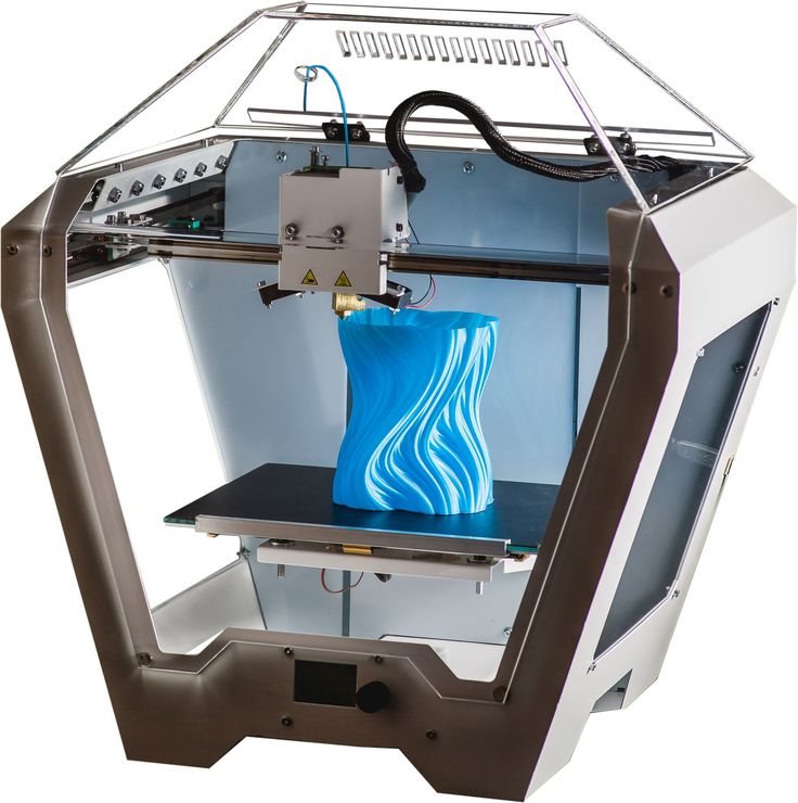 After the handle was chrome painted, I painted the “leather” with a burnt umbre brown acrylic paint.
Then I finished painting the hammer with some personal touches added.
Previous
Next
After going through the effort of glueing the pieces together, I decided it might be easier to print & post-process in one piece.
These are some of the resources I used when designing my hammer:
- https://en.wikipedia.org/wiki/Mjolnir_(comics)
- http://marvelcinematicuniverse.wikia.com/wiki/Mj%C3%B8lnir
- http://vignette2.wikia.nocookie.net/marvelcinematicuniverse/images/2/25/Mjolnir.png/revision/latest?cb=20140129001244
- http://www.instructables.com/id/Mjolnir-Thors-Hammer/
I’d love to hear your feedback!
You can find me on twitter or email at: [email protected] to chat about the process or my next HUGE cosplay project!
Yep, the rumors are true! The next round of re:3D internship openings are live!
The summer we will have a full cadre of interns spanning design, hardware, marketing, and software.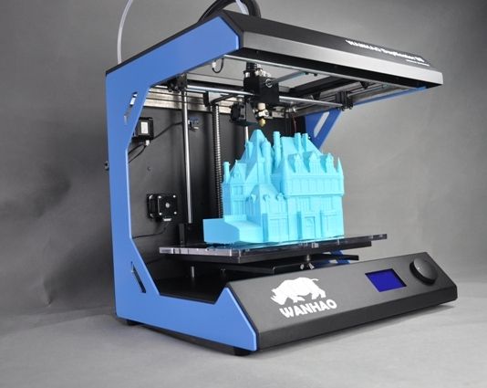 Positions range from fulfilling creative to outright crazy projects and we can’t wait to get started with our newest batch of teammates when the program kicks off June 1st.
Think you’re up for the challenge? Check out all of the positions at: www.re3d.org/careers/ and submit your application here by May 10th!
2014 Summer Design Intern Alberto showing off his Gigabot inspired monocle.Questions? Contact: [email protected]
internships jobs
Working with 3D printing. Where to begin?
Konstantin Ivanov, co-founder of 3DPrintus and DigiFabster, mastered 3D printing on his own. He said that studying theory, browsing thematic sites and communicating with domestic and foreign experts helped him in this. However, theory is theory, and practice has not been canceled. Therefore, below we will analyze what to do if you want to work in the 3D industry.
According to Konstantin, at the very beginning of the development of additive technologies, it is important to understand in which particular area you want to become a professional.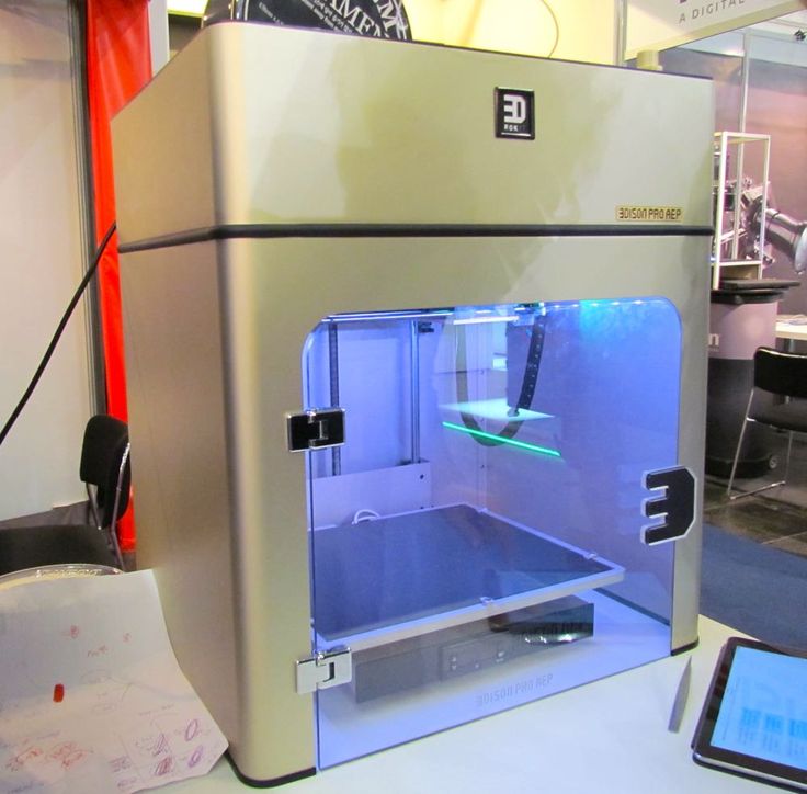
3D modeling
3D modeling includes a wide range of tasks that will be of interest to designers, engineers, planners, architects, etc. Having a basic engineering education will be a significant advantage.
Specialists in this field create a 3D model of an object, which will subsequently be printed. Today, craftsmen who can model metal parts, medical products, and all kinds of engineering prototypes are in great demand.
You can learn 3D modeling on your own using the content on the websites Demiart.ru, Gamedev.ru, Render.ru, as well as in thematic groups on social networks. You can also take online courses. Among the good foreign resources for online learning is Gumroad.
Software developer
Very sophisticated software is required to work with 3D printers and 3D models. Therefore, experts in this field are highly valued.
Knowledge of geometry will be a significant advantage, since today the specialty of the developer of geometric algorithms is especially valued. Also, software development requires full-stack programmers who know AngularJS and Ruby on Rails.
You can become a software specialist by completing a university thematic course, as well as through self-education. A good knowledge base can be obtained at Innopolis University.
Technician
One of the most interesting areas, which involves the development of new, better, more understandable and efficient devices. Knowledge in the field of mathematics and physics is important here. An engineering background would also be an advantage.
The most sought-after professions related to the creation of technology are assembly, electronics, optics, and mechanical engineers.
You can learn the intricacies of working with technology at the Moscow State Technical University. Bauman. However, to gain experience in the design of equipment is possible only in practice. In addition, along the way, you will have to master the technologies and 3D printers that already exist on the market.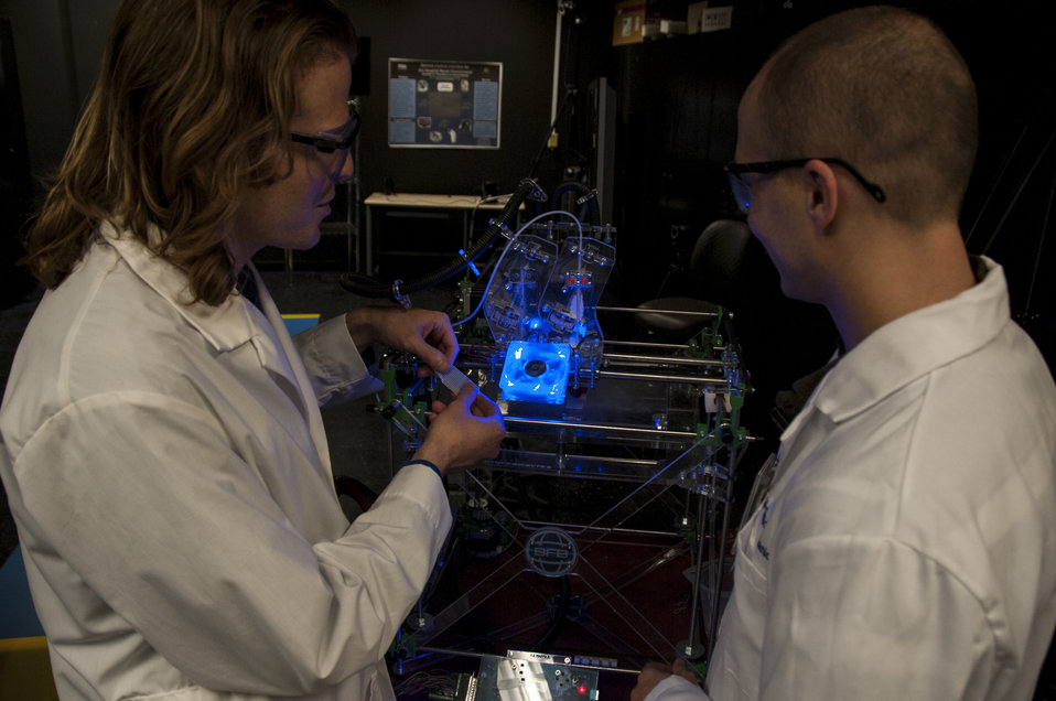
Material developer
The characteristics and quality of finished products directly depend on the type and quality of consumables. Therefore, specialists in the development of new filaments, powders, etc. are in great demand on the market.
Knowledge of physics and chemistry is indispensable in this area. To get them, you can finish the chemistry department at one of the Russian universities.
I would like to repeat that theory does not make sense without practice. Therefore, after training, a 3D printing expert advises you to get an internship at any company that successfully operates in this field.
results of practice for students / Sudo Null IT News
Summer is the time for practice for university students. The Raccoon Security team regularly invites everyone to personal and group internships. This summer, students from the department of IU4 MSTU came to us for an internship. N.E. Bauman. For a whole month they took an active part in the production processes and put into practice the theoretical knowledge gained at the university.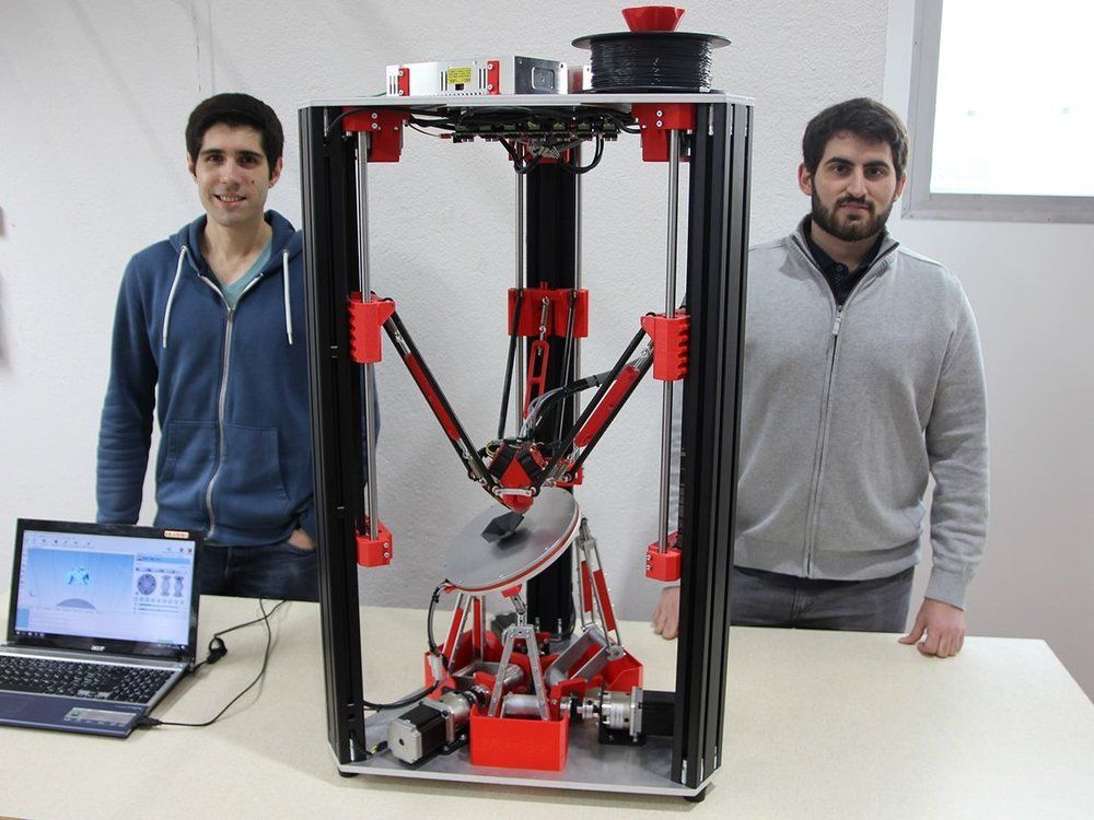 We decided to talk about this internship and share the feedback of the students who participated in it.
Internship format
The topic of the internship was “Developing the concept of home autonomous wireless camera for the safety of young children”. The internship was held in the practice format, ten students of the Moscow State Technical University named after V.I. N.E. Bauman, who have just switched to the third year in the direction of "Design and technology for the production of electronic equipment" (Department of IU4).
Initially, we planned the program for four weeks, for which the students had to:
-
research and analyze the market for stand-alone wireless cameras;
-
perform a circuit analysis of an existing set of devices;
-
field test these devices and compare their actual performance with the declared;
-
draw up the terms of reference, block diagram and concept of your device.
As additional events, we have planned presentations on the following topics:
-
Microcontrollers and FPGAs.
 What is it and how to live with it?
 -
“Developing your device from A to Z”;
-
Introduction to 3D printing;
-
“Why study at PS4?”.
Students were divided into three teams of three to four people. Next, we created a chat in Telegram and a group in GitLab with separate projects so that it would be convenient for teams to communicate with curators. A workplace was prepared for each student: a computer with Ubuntu , fast Internet, Wi-Fi, air conditioning. To restore strength - tea, coffee, sweets and cookies ... :)
Goals
The main goal of the practice is to form basic knowledge about the key stages of creating a device. We wanted students to learn:
-
search and critical analysis of information;
-
team work;
-
systematic approach in conducting practical research;
-
registration of research results;
-
application of basic approaches to device design.
As organizers, we wanted to first of all involve students in personal internships with subsequent employment, as well as to make an overview of the current market.
Start
On the first day, the students showed their best side: during the introductory presentation and a short tour, they asked interesting questions and demonstrated knowledge in the field of applied electronics and programming. Someone already knew how to repair motherboards, someone was familiar with programming in C/C++ and Python , and someone developed apps on Android and iOS .
The next day we started the practice program. It turned out that students are able to qualitatively solve the tasks set much faster than we thought. Students have already begun to ask to quickly move on to practical actions: to introduce them to the development of microcontrollers (MC) and FPGAs, soldering and wiring printed circuit boards, as well as 3D printing.
We have decided to expand the internship program so that students do not get bored. I had to urgently supplement and rebuild the existing plan.
1. For soldering work, we have designed a board in the format pcb-challenge .
2. For tasks related to MC and FPGA, created separate projects in GitLab and distributed debug boards. For working with FPGAs, we prepared a small workshop on boards from the company Altera . Tasks for development on the MK (we chose STM32 as a platform) had to be thought out individually along the way.
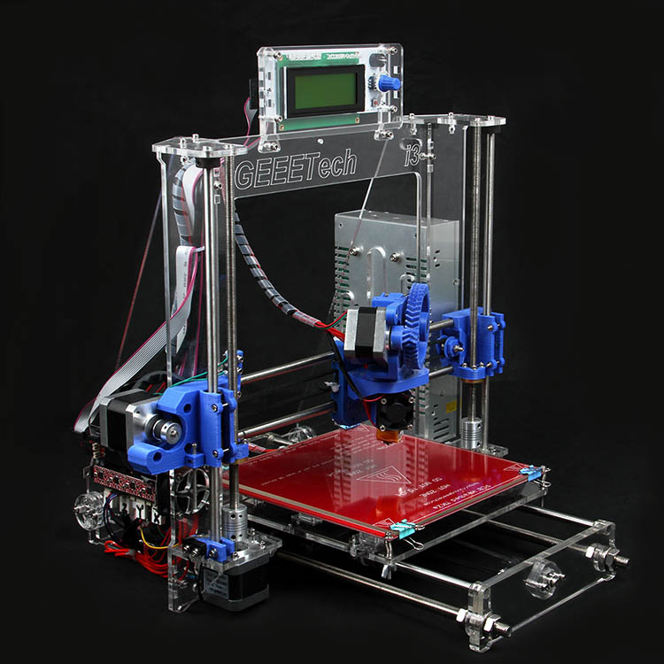
3. For 3D printing, we moved one of the 3D printers to the students' classroom and showed how to use it.
Further on in the text we will give some excerpts from the feedback of our students. The spelling, punctuation and style of the authors have been retained wherever possible.
First week. Market Research
In the first week, the teams were required to:
-
conduct market research for standalone wireless cameras;
-
create a list of devices;
-
highlight the main specifications;
-
highlight the advantages and disadvantages of each model based on consumer feedback.
For each command, one of the highest priority search criteria was determined: image quality , miniaturization , availability of unique functions .
At the output, we wanted to get a systematic report in Markdown'e with tables and conclusions.
During the execution, one of the teams decided to apply their knowledge in the field of SQL - to create their own camera dataset and perform characterization using Python. We were pleasantly surprised by this unexpected approach.
One of the many graphs that students received after processing their databaseOf course, for such processing, it is desirable to have a large amount of data, which the students learned about in the process and warned us in a timely manner. But we decided that in the framework of training we can neglect this. They designed the final report as an HTML page.
Cyril
To be honest, the first week was a bit boring, namely the analysis of the device market.
But then everything was perfect. We disassembled the devices themselves, studied their principle of operation and what the elements of the device diagrams are for, and later we ourselves developed a functional diagram of operation for them, thought through what elements are needed and how they will interact.
Programming of microcontrollers based on STM32 was the most interesting for me. Alexander [curator] spoke not only about the basic things needed to work with MK, but also about the subtleties that were from his experience. In particular, when connecting the L3DG20 gyroscope, he said that the connection is only half the trouble, the main problem is data processing, which I did not believe at first. And now I'm studying digital signal processing...
Optional tasks. Soldering SMD components
Somewhere in the middle of the second week, our pcb-challenge board was ready. As soon as the boards "came" to the office, we decided to solder one piece and see how long it would take an experienced specialist to solder SMD components. Armed with a simple soldering iron, Nikita, one of the practice's curators, was able to solder all the components in about an hour.
The very next week students started trying their hand at soldering SMD components. Some students already had experience with a soldering iron, so someone spent no more than three hours on installation, while someone soldered all six.
PCB-challenge soldering process. The board contains LEDs and resistors of different sizes, including 0201 :)Nevertheless, almost all students managed to install SMD components on their own. If the elements are soldered correctly, then all LEDs should light up with the same brightness.
The result is a personal keychainFedor
In general, I can say with confidence that this practice was surprisingly successful for me. I liked that the organizers of the practice approached the process of our training very responsibly: they arranged small lectures, helped with emerging problems.
I especially liked the organization of our work: boards, tasks, To-Do List, etc. Still, the most important thing for me is people who are really interested in teaching us [students] something new, to tell and show – it costs a lot.
Second week. Circuit analysis
To perform circuit analysis, ten wireless cameras were purchased from AliExpress , , two of each model. It was proposed to disassemble one of the chambers, and leave the other for field testing.
Of course, it would be much more interesting to purchase certain models based on the results of the first stage, but given the time constraints, we decided to purchase cameras in advance.
Circuit analysis of some modelsThe students not only managed to find most of the datasheets for the discovered microcircuits, but also made quite plausible block diagrams of the disassembled devices.
One of the resulting block diagramsArseniy
The practice was excellent, it is worth noting the good atmosphere and the opportunity to ask questions, which are always answered and unclear points are explained.
Didn't like a lot of reports at the beginning.
I learned how projects are carried out, what you can do in such companies, what things you need to know and be able to do in my specialty. You can reduce the number of reports and add even more practice tasks.
Optional tasks. Programming MC and FPGA
During the first week, one of the curators, the leading specialist Vadim, read to the students an introductory report about MC and FPGA. And by the beginning of the second week, we decided to do optional tasks on programming microcontrollers and FPGAs in our free time from the main program.
Six people wanted to work on hardware programming at once. Four students chose STM32, and two students chose FPGAs. We started programming the MK with simple tasks for blinking LEDs and studying interrupts. On the FPGA, students started by building the simplest counters on LEDs and seven-segment indicators.
In a few weeks, we mastered working with GPIO, interrupts, timers, UART and SPI based on STM32 from scratch After completing the introductory tasks, we began to deal with UART and SPI. Among the tasks were the following:
-
sending commands to turn on/off the LED via UART;
-
counter transfer via UART when button is pressed;
-
calculator with UART interface and SPI display;
-
writing arbitrary strings to the controller's flash memory via UART;
-
work with ADC and PWM, adjust the brightness of the LED with subsequent display of the graph on the display via SPI.
Denis
The practice turned out to be quite entertaining. The informal atmosphere, communication on an equal footing contributed to the rapid rallying with the curators, and made it possible to quickly find a common language with them.
The practice program is quite interesting. Everyone, at their will, could get acquainted with the programming of a microcontroller or FPGA, the process of soldering and assembling their own circuit, printing on an FDM printer.
In general, we got an indispensable experience, which one way or another will really come in handy in the future.
As for the FPGA, the students first implemented a simple counter with LED display and got acquainted with the PLL module. The next task was to create a counter on a seven-segment indicator, which could be increased and decreased by pressing a button. Here the students encountered such a phenomenon as contact bounce.
Unfortunately, we did not have enough time to complete the third task. It was designed for two weeks and consisted in the implementation of its own UART module, followed by sending and receiving a message encoded with a Caesar cipher.
But one way or another, we managed to get students interested in the development process on FPGAs. And one of them even ordered his first debug board from AliExpress :)
32-bit counter project, high 4 bits driven to 4 LEDs. The accumulation of the counter is noticeable to the human eye. With the help of a toggle switch, you can change the accumulation rateTimur
The practice process was not boring and varied.
In this practice, I learned:
1) more accurately analyze the market for certain devices;
2) conduct primary circuit analysis of the device;
3) test devices.In my opinion, the practice went well. I liked all the stages of the practice, because the skills that I acquired will be useful to me in the future not only at school, but also at work.
The next step was to conduct field tests. Very often it turns out that the characteristics declared by the manufacturer by AliExpress do not match the real ones. If this cannot be understood at the stage of circuit analysis, then real tests and measurements will help in establishing the truth.
A Full HD image taken with one of the cameras turned out to be 1280x720 resolution, and quite blurry at that Here is a list of criteria and characteristics that the students used to test:
2) shoot in room lighting;
3) shoot in street light:
- in the direction of the sun's rays;
- against the direction of sunlight;
4) shoot in poor lighting:
- with IR illumination;
- without IR illumination;
5) check connection stability:
- image delay;
- image breaks;
- operating range;
6) check how the device works with storage:
- file organization;
- compression ratio;
- format.
Image in 2K resolution from another camera. In fact, all video and photos are shot at 360pA on this camera, the manufacturer also claimed 1080p, but the maximum resolution is 1280x720. Artifacts present
Our suspicions were confirmed: most of the declared characteristics did not correspond to the real ones. One of the cameras turned out to be simply inoperable, and among all the cameras there were only a few copies that could somehow shoot stably in more or less good quality.
Plato
It was very nice that the curators were graduates of our department. We very quickly found a common language. Thanks to the constant support of Alexander [the curator], the work has never stood still. In practice, it is very important that the curator has work experience, and we got it.
On the plus side, I would like to note that you can also learn more about how other departments of the company work, and not just about the one in which you are doing your internship.
The work was divided into teams, but the projects were similar, so we all came together to perform common tasks and got to know each other better, which is undoubtedly great.
Optional tasks. Printing models on a 3D printer
By the middle of the third week, a specialist in the hardware development department, Nikita, gave the interns an overview report about 3D printing: the most popular 3D printers and the most common problems for beginners during printing were listed.
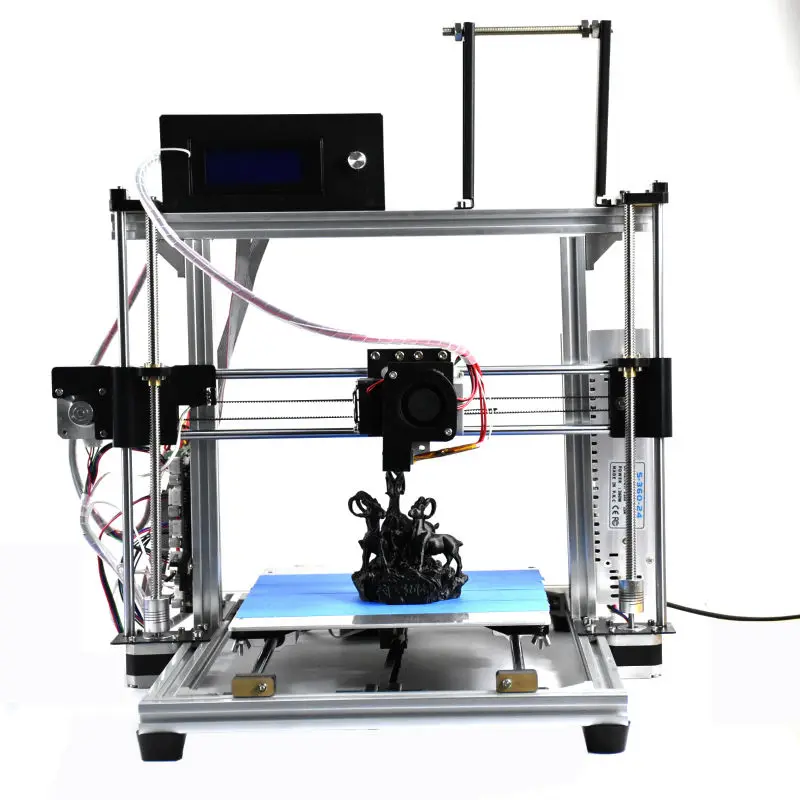
We tell the trainees about the basics of 3D printing and what kind of printer they can buy to start withOn the same day, we decided to transfer one of our combat printers, the old Felix 3.0, to the students in the classroom. The transportation was successful, and the trainees quickly mastered searching for models on the Thingiverse and working with the slicer. PETG plastic was used for printing.
We thought about doing some team 3D printing task, but unfortunately we didn't have enough time for that. Therefore, we simply limited ourselves to printing finished models on a 3D printer. Judging by the fact that a whole reel of plastic was gone in a week, the students liked it too :)
Eugene
sizes, even such as 0201 type resistors, analyze and propose various solutions to improve the electronic device.
I liked that all the specialists with whom I had any contact were well qualified. Every week, the most luxurious lectures of various profiles were held, which expanded the horizons and understanding of many things. Of course, in this extremely fleeting month it is impossible to cover everything, which is a pity.
Fourth week. Development of own concept
In the final stage, we wanted the trainees to draw up the terms of reference and the concept of their own camera, using the knowledge gained during the practice. As an additional task (with an asterisk), it was proposed to develop a 3D model and visualize your device.
One of the teams decided to make a camera based on the idea of scalable modules. Here's what they got:
One of the resulting concepts of a modular camera is a block diagram One of the resulting concepts of a modular camera is a 3D model in Autodesk Fusion 360Anastasia
I can say that during the internship I significantly improved my soft skills. I understood what it means to work in a team, became more organized, sociable, began to systematically approach the solution of any problem. Throughout my work, I learned to critically analyze information and choose the right selection criteria.
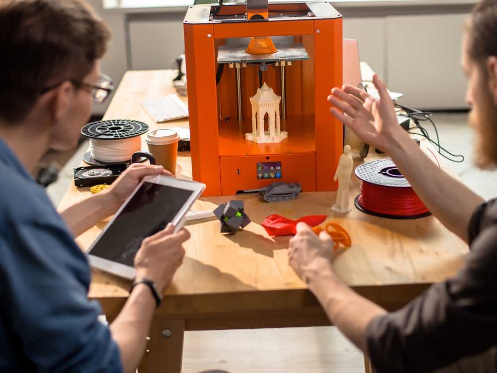
I really liked that in addition to the main task, I was given the opportunity to get acquainted with microcontroller programming, create figurines on a 3D printer and master Markdown.
I would like to point out several advantages of the practice, the first of which is an excellent team of specialists and a great atmosphere.
Another plus is a cool work plan. It was very interesting to look at the key stages in the creation of the device. We were given the opportunity to come up with the concept of our own video camera, where I could show my creative skills.
As a sophomore, it's hard to imagine what we can expect at the place of work, and the practice of this format gives a very clear and clear idea of what we will face.
Conclusion
The month flew by unnoticed, and the practice came to an end. All tasks assigned to the students were completed qualitatively and on time. During the practice, we conducted several interviews and agreed on subsequent personal internships in individual areas. As a conclusion, we quote the words of the chief curator of the practice - Alexander.
Alexander
Initially, I had some doubts about how the internship would go, because it was my first experience of managing a team, albeit a small one.
All doubts quickly disappeared as soon as I saw the burning eyes of students and interest in development and programming. We very quickly managed to build trusting relationships and find a common language with students. I enjoyed challenging them, guiding them and answering questions. In the process, I also learned a lot and outlined new points of personal growth.
I hope that this month I was really able to interest and teach the trainees how to develop their own devices. Lay a small foundation for programming and further interest in microcontrollers and FPGAs.
I would like to thank all the students and my colleagues who helped me to conduct this practice and made presentations: Kirill, Nikita, Vadim and Anton.
We constantly conduct individual internships and would be grateful if you share a link to this article with those who might be interested.
You can apply for an internship here .