Bitprint 3d printer
bitprint | bitprint - Bits printer macro
kandi X-RAY | bitprint Summary
bitprint is a C library typically used in Modeling, 3D Printing applications. bitprint has no bugs, it has no vulnerabilities, it has a Permissive License and it has low support. You can download it from GitHub.
bitprint - Bits printer macro.
Support
Support
Quality
Quality
Security
Security
License
License
Support
- bitprint has a low active ecosystem.
- It has 3 star(s) with 1 fork(s). There are no watchers for this library.
- It had no major release in the last 12 months.
- bitprint has no issues reported. There are no pull requests.
- It has a neutral sentiment in the developer community.
- The latest version of bitprint is current.
bitprint Support
Best in #3D Printing
Average in #3D Printing
bitprint Support
Best in #3D Printing
Average in #3D Printing
Quality
- bitprint has 0 bugs and 0 code smells.
bitprint Quality
Best in #3D Printing
Average in #3D Printing
bitprint Quality
Best in #3D Printing
Average in #3D Printing
Security
- bitprint has no vulnerabilities reported, and its dependent libraries have no vulnerabilities reported.
- bitprint code analysis shows 0 unresolved vulnerabilities.
- There are 0 security hotspots that need review.
bitprint Security
Best in #3D Printing
Average in #3D Printing
bitprint Security
Best in #3D Printing
Average in #3D Printing
License
- bitprint is licensed under the Apache-2.0 License. This license is Permissive.
- Permissive licenses have the least restrictions, and you can use them in most projects.
bitprint License
Best in #3D Printing
Average in #3D Printing
bitprint License
Best in #3D Printing
Average in #3D Printing
Reuse
- bitprint releases are not available.
 You will need to build from source code and install.
bitprint Reuse
Best in #3D Printing
Average in #3D Printing
bitprint Reuse
Best in #3D Printing
Average in #3D Printing
Top functions reviewed by kandi - BETA
kandi's functional review helps you automatically verify the functionalities of the libraries and avoid rework.
Currently covering the most popular Java, JavaScript and Python libraries. See a Sample Here
Get all kandi verified functions for this library.
Get all kandi verified functions for this library.
bitprint Key Features
Bits printer macro
bitprint Examples and Code Snippets
No Code Snippets are available at this moment for bitprint.
See all Code Snippets related to 3D Printing
Vulnerabilities
No vulnerabilities reported
Install bitprint
You can download it from GitHub.
Support
For any new features, suggestions and bugs create an issue on GitHub. If you have any questions check and ask questions on community page Stack Overflow .
▷ bitprint 3d printer 【 STLFinder 】
▷ bitprint 3d printer 【 STLFinder 】1614557 3d models found related to bitprint 3d printer.
3D Printer
grabcad
3D Printer
3D PRINTER
grabcad
3D PRINTER
3d printer
grabcad
3d printer
3D Printer
grabcad
3D Printer
3D Printer
grabcad
3D Printer
3d printer
grabcad
3d printer
3D printer
grabcad
3D printer
3D Printer
grabcad
3D Printer
3d printer
grabcad
3d printer
3d printer
grabcad
3d printer
3d Printer
grabcad
3d printer
3D Printer
grabcad
3D Printer
3D Printer
grabcad
3D Printer
3d printer
grabcad
3d printer
Printer 3D
sketchfab
Printer 3D
3D Printer
grabcad
3D Printer
3D-Printer
grabcad
3D-Printer
3D Printer
grabcad
3D Printer
3D Printer
grabcad
3D Printer
3D PRINTER
thingiverse
3D PRINTER
3D printer
grabcad
3D printer
3D printer
grabcad
3D printer
3d printer
grabcad
3d printer
3D Printer
grabcad
3D Printer
3d printer
grabcad
3d printer
3D Printer
grabcad
3D printer
3D printer
grabcad
3d printer
3d printer
thingiverse
3d printer
3d printer
grabcad
3d printer
3d printer
grabcad
basic 3D printer
Generating a 3D model from a bitmap image
Generating a 3D model from a bitmap image
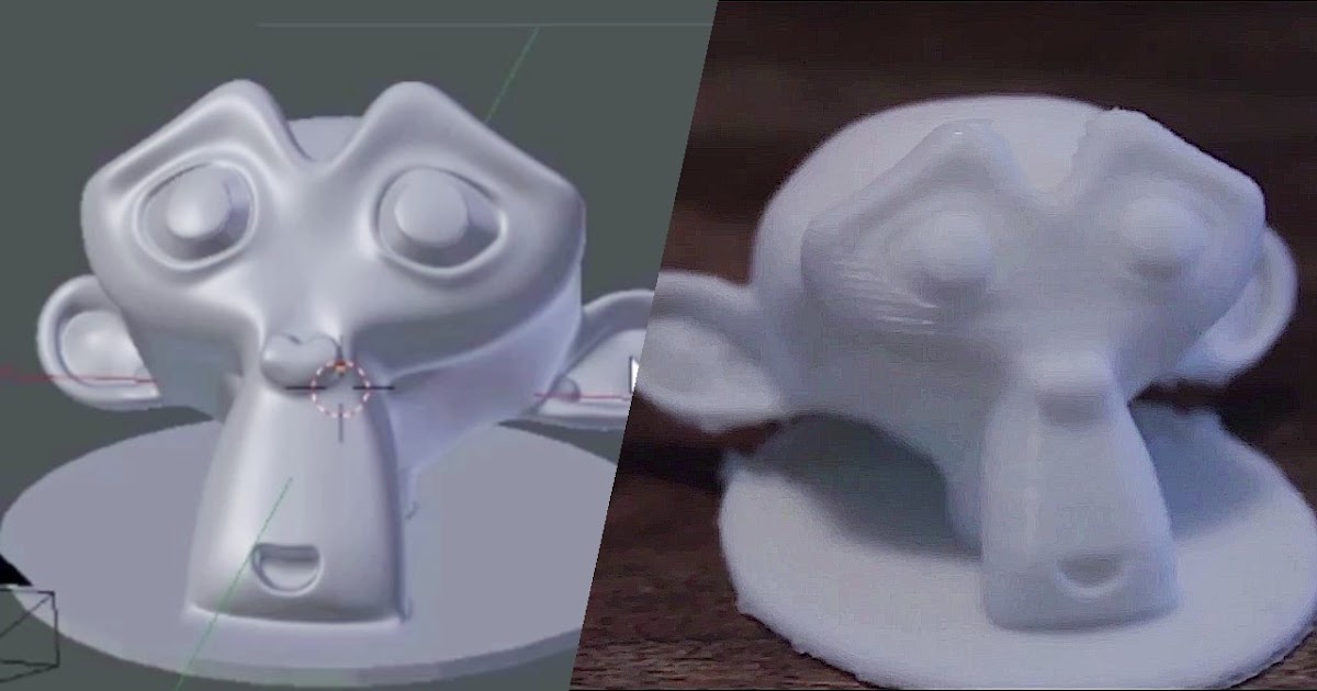
There are a number of programs that allow you to turn a photo into a bas-relief using the 3D printer . However, when the author was faced with the work of creating a large number of souvenir medals with portraits of people from photographs of different quality, he wanted to do such work with a more convenient tool.
When preparing a bitmap to create an STL model that can be printed on 3D printer or made on a CNC milling machine, you have to repeatedly retouch the image in a graphics editor, generate an STL file, view it with a special viewer, retouch again and repeat the whole process again. With the accumulation of experience in such work, the number of such cycles decreases, however, in many photographs, light and shadows are arranged in such a way that the bas-relief obtained on the basis of the brightness of the pixels in the image does not always correctly convey the relief of the original.
In order to make the described process more productive, the author decided to speed up the process of generating and viewing the STL file as much as possible to decide whether to continue retouching the image.
Developing a convenient tool for such work, the author proceeded from the following.
To speed up the process of generating an STL file of the desired quality and reproducibility of results, all necessary conversion parameters must be specified in numbers, saved for use or change in the next cycle, minimizing keyboard and mouse work. The program must build a triangulated closed surface to be able (if necessary) to edit it in various 3D editors. The generated model should be automatically rendered in the selected external viewer for STL files. And, of course, the program that performs the tasks must be cross-platform or run on a remote server from the user's browser.
For obvious reasons, the Java language was chosen to implement the program.
The program interface for the local computer is as follows.
The Image selection button opens the dialog for selecting the required raster file. The image can be color or grayscale, with or without an alpha channel. Working with an image in grayscale is more convenient when retouching.
The selection made, as well as the values of other parameters, is saved for the next cycle of bas-relief formation.
Displays the name and location of the selected file and its dimensions in pixels.
Enter the desired size of the generated model. It is enough to enter the height or width of the model, the second parameter is calculated automatically.
Parameter Step sets the step in pixels for processing the original image. A step larger than 1 can be used either when processing too detailed images to avoid too much accuracy of the model that cannot be realized by the printing device, or as one of the means of smoothing the surface of the model. For example, with the given parameters, the display of each pixel requires an accuracy of 35/834/3=0.014mm, which must be consistent with the capabilities of the printing device.
Parameter Zmax sets the thickness of the bas-relief in millimeters. It should be remembered that raster images have 256 gradations of brightness, therefore, to display all the gradations of brightness in our example, the thickness of the print layer is 2mm/256=0.008mm. When preparing the model for production, the slicer will reduce the number of layers in accordance with the settings of the printer. If this parameter has a negative value, the bas-relief will be formed not convex, but concave.
Parameter Base sets the thickness of the base in millimeters. This parameter has a purely technological meaning. The base is needed to securely connect the model to the working surface of the printer during printing.
Parameter Smoothing is used to smooth the surface of the model. To calculate the height of each surface point in our example, we use the average of the heights of three points (including the current one) vertically and horizontally. If the parameter value is 1, smoothing does not occur.
Any convenient program can be selected as a viewer for the created model. In our example, the excellent free program Best STL Viewer is selected, which starts and starts without burdensome dialogs.
This program allows you to view the model from different angles and at different scales. After closing the viewer window, you can continue working in the graphics editor to bring the image to the desired quality.
Working with a servlet located on a remote Java 9 server0004
In the browser, the URL of the servlet is entered in the address bar (in this example, localhost is used) and a WEB page is formed on the client side to enter the necessary parameters and transfer them to the server. All calculations are performed on the server side and the address for downloading the STL file is returned to the user. STL files are created in binary format.
Obsolete files on the server are destroyed automatically. The servlet provides thread safety, which allows a large number of users to work with the servlet at the same time.
The video showing the work of programs in real time can be viewed by the link:
Author of the article - Vitaly Traiger, Email
90,000 Subpixel smooth smoothing Prints or proper anti -oliasTechnical
Subscribe to the author
Subscribe
Don't want
30
Hi all! I continue to write in my blog about photopolymer printing using DLP projection technology. Today I would like to touch upon the issue of improving the surface quality of printouts. Not so long ago, Autodesk talked about the so-called sub-pixel anti-aliasing - this is a method that uses different pixel depths (halftones) to smooth out the 'artifacts' resulting from converting a vector 3D model into a discrete slicing of bitmap images. There was a translation of this article on 3dtoday, you can read it at the link http://3dtoday.ru/blogs/news3dtoday/50-shades-of-gray-or-subpixel-smoothing-for-the-projection-of-3d-print/ I will briefly describe the essence of the problem, it is most convenient to do this using the example of an ordinary straight line forming one of the sides of the model, for simplicity we will take this case, but in general everything described below is true for more complex shapes. So, if the straight line of the original model is not perpendicular, but at an angle to one of the axes of the projector pixel grid, then when converted to bitmap images, it will be represented using a ladder, and this ladder will be visible even at super high resolution, due to the fact that it usually has a larger step compared to the layer thickness. Autodesk, on the other hand, shows in its experiments that if you make a gradient of halftones in places of steps, you can smooth the surface and get a better result when printing.
 It looks like this:
Well, let's try to illustrate the problem in practice, for this I took a motorcycle model (you can download it in my profile) and printed it out without applying any smoothing. Printing was carried out on an EGL2 printer at the highest possible XY resolution - 22 microns, layer thickness in Z - 20 microns.
Let's choose the desired angle of incidence of light and try to bring the wing as close as possible. As you can see, despite the high print resolution along the XY axes, we have a pixel ladder on the wing and some other parts.
Let's see where it comes from, for this I took a layer file at the appropriate cutting height and looked at how the wing is represented:
in fact, we see artifacts of converting the vector representation of the model into a raster one.
Let's try to apply different types of smoothing to the model. I had at my disposal 3 slicers capable of applying Anti-alias or anti-aliasing - this is the well-known Creation Workshop, the NanoDLP slicer (or the SLC2PNG utility) and the commercial Envisiontec Perfactory RP slicer. After cutting the model with these programs, I got the following picture:
Already from these results it was possible to draw some conclusions, the algorithm that is described by Autodesk is used only in NanoDLP and Envisiontec's slicer. Creation Workshop uses a different algorithm. Anti-aliasing in CW is already applied directly to pictures without analyzing the original vector information, perhaps this is Gaussian blur or some other raster algorithm, which is also available in numerous graphics programs. And if the algorithm is applied to already graphic slicing, without taking into account vector information, then it becomes impossible to determine whether the angle formed by 3 pixels is a real detail of the model or is it an artifact that arose when converting a vector to a raster. Accordingly, the use of such algorithms, in my opinion, not only does not solve the problem of smoothing ladders (judging by the picture, they just got a different ladder configuration), but also blurs the real details of the model. Well, let's print the models and check my assumptions. Due to the fact that the Envisiontec slicer is not freeware and is not available to the public, I made a printout of the models sliced by Creation Workshop and NanoDLP and compared them with the model without anti-aliasing:
The first thing that caught my eye was the NanoDLP sliced model is much glossier than the regular model and the CreationWorkshop sliced model, while the CW model appears to have a 'loose' surface. Unfortunately, a regular photo is not able to convey these impressions, so I took an electron microscope:
To start with CreationWorkshop (above) and a regular model:
In my opinion, my assumptions were confirmed. We did not remove the ladder, but only changed its configuration, in addition, due to the application of anti-aliasing directly to the pictures, we blurred the details and got a loose surface from the use of halftones in the wrong places.
Now NanoDLP (above) and the regular one:
Although the ladder is visible in the microscope, it is much less pronounced and as a result the glossy surface of the model, the difference is especially visible on the wheel.
In my opinion the algorithm described by Autodesk and used by default NanoDLP works well. Its software implementation is quite complicated, unlike raster algorithms applied to pictures, because you need to lay it at the cutting stage and analyze the geometry of the original model. At the moment, NanoDLP or their SLC2PNG utility is the only freely distributed implementation of this algorithm, while it is implemented only along the XY axes. An analysis of the results of slicing the Envisiontec Perfactory RP slicer showed that this algorithm was implemented there along all 3 XYZ axes, while I had the 2014 version at my disposal, i.