Blender prepare model for 3d printing
How to prepare objects for 3D printing in Blender (Suzanne example) - CG Cookie
3D printing your Blender models is one of the most exciting techniques.
What's cooler than magically materializing a digital 3D mesh into a tangible real-life object?
But a digital object needs preparation in order to be suitable for 3D printing.
This article shines a light on preparing a mesh for 3D printing in Blender, divided into a number of checks and options - with Suzanne as our example.
What you'll find in this article:
- Check 1: Does the mesh have enough polygon detail?
- Check 2: Does the object need support?
- Check 3: Is the Blender mesh manifold?
- Check 4: Are the object's dimensions correct?
- Option 1: Do you want to paint your 3d model?
- Option 2: Do you want your 3d printed object to be hollow?
- The final step: exporting your model for 3D print
Check 1: Does the Blender 3Dmesh have enough polygon detail?
In virtual 3D space, low polygon detail can be obscured using a shader, giving a 3D object’s surface the illusion of smoothness in renderings.
This effect can’t be translated to a 3D-printed object, so you’ll need to ensure that an object has sufficient polygon detail to avoid visible facets, unless you’re aiming for a stylized execution.
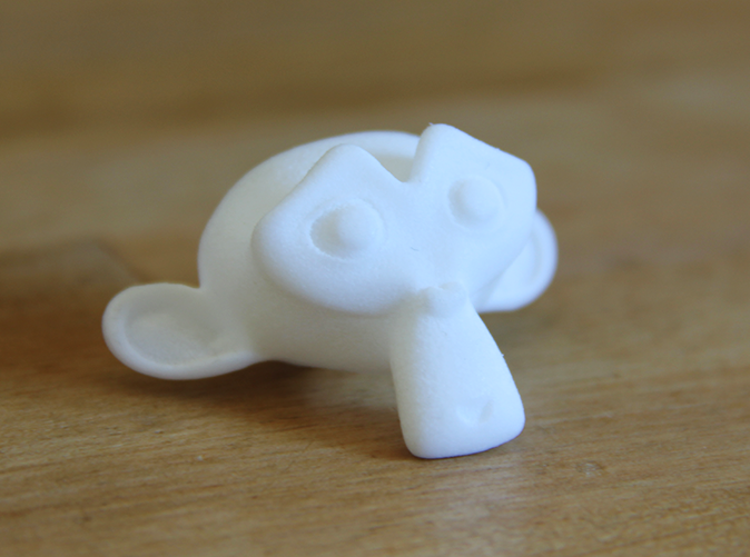
Let’s delete all default scene elements, and add a Suzanne (Monkey) head to Blender.
The default monkey head has a very coarse amount of polygons.
While the head is selected, press Control + 3 to add a Subdivision modifier with three subdivision iterations.
This will smooth out Suzanne’s surface, so we’ve got proper polygon detail for 3D printing.
Hover your pointer over the Subdivision modifier and press Control + A to apply the subdivisions to the monkey head.
Check 2: Does the object need support?
In virtual 3D everything floats by default. But once 3D-printed, an object will fall over if there is insufficient balance.
In the case of Suzanne, you could put her on a table with a tilted head, but it might still roll to the side.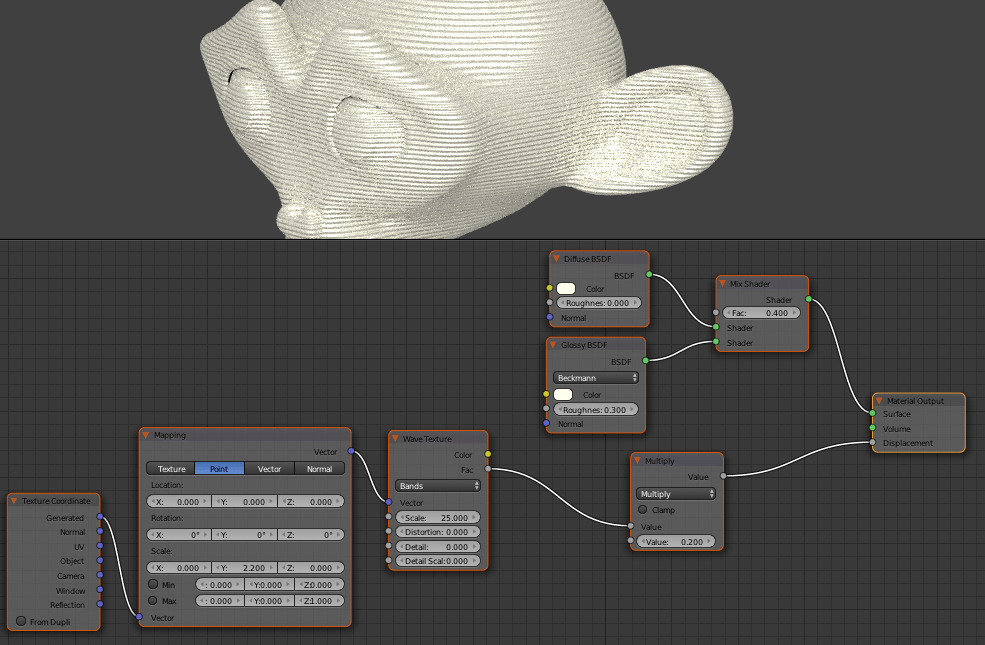
So let’s create support, so the head can keep the same orientation as in the 3D viewport.
Orbit the viewport to view Suzanne’s chin, then Shift + right-click on the bottom of her chin to place Blender’s 3D cursor there.
Press Shift + A ➔ Mesh ➔ Cylinder to add a cylinder to the 3D cursor position. Enter Edit Mode and manipulate the cylinder vertices as you wish, moving vertices, adding edge loops, and extruding faces.
I’ve kept it simple and minimalistic. Added two subdivisions with the subdivision modifier, extruded a middle part, and added some edge loops, also inside the caps, to make the features a bit sharper.
So before you 3d print, consider these two things:
- The balance. Suzanne’s large head volume needs to be taken into account when creating support.
- The robustness. If your mesh has small or thin features, those might break off during the 3D printing process or afterward. In the case of Suzanne, make sure the support and Suzanne’s chin are overlapping enough to handle the weight of the entire head.
Check 3: Is the Blender mesh manifold?
Although Blender’s viewport shows us something that seems ready to be 3D-printed, some more work is still necessary.
In this case, the monkey mesh exists of three separate parts, featuring open edges: the head and two eyes.
In order to be ready for 3D-printing, an object needs to be manifold, or ‘watertight’.
This means the object should have a continuous surface without loose parts, open edges, and other anomalies that might exist in virtual 3D space.
How to make a Blender object 'watertight' for 3d printing:
Make sure the support has its subdivision modifier applied by hovering your pointer over the modifier and pressing Control + A to apply it.
- Select both the head and the support in Object Mode, then press Control + J to join the objects into one mesh.
- Add a Remesh modifier, make sure Voxel mode is active and set the Voxel Size to a detail level you like. Using the default Suzanne dimensions, I set the Voxel Size to 0.
 007.
007. - To soften the artifacts caused by the voxel remeshing, add a Smooth Corrective modifier, check Only Smooth, set the Smooth Type to Length Weight and adjust the Repeat value to your liking. I’ve set the Repeat value to 10.
- Hover your pointer over the Remesh modifier and press Control + A to apply it, then do the same with the remaining CorrectiveSmooth modifier.
The entire model and its support are now one seamless, manifold mesh that’s almost ready for 3D printing.
Check 4: Are the object's dimensions correct?
So far we’ve worked with Blender’s default monkey head size, which is 2 meters (approximately 6.5 feet).
You would need quite a large 3D printer, a huge amount of print materials, and a lot of space in your room for that, not to mention the necessary expenses.
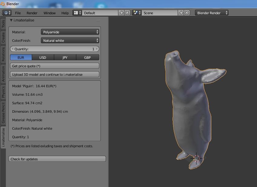
You can check your object’s scale in the N-key panel ➔ Transform ➔ Dimensions.
Make sure Blender is set to your local unit system
As a European resident, I’m working with metric units, so for the scope of this article, it would be convenient if US readers would change their Blender units to metric as well, if necessary.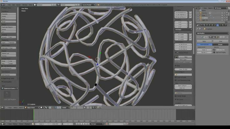
This can be realized in the Scene Properties tab ➔ Unit System ➔ Metric.
After setting the Unit System to Metric, one more important setting needs to be changed: set the Unit Scale to 0.001.
This will synchronize Blender units with a scale of millimeters, because Blender’s 1.0 Unit Scale equals 1 meter. Most 3D file formats used for printing use millimeters for the dimension values.
How to resize our Blender masterpiece to a proper scale:
- Select the object, and make sure the Transform ➔ Dimensions values are visible in the N-key panel.
- Press S to activate Scale mode, and type a scale factor that makes the object’s dimensions correspond to the real-life size you desire. (I’d advise resizing the model to around 0.1 meters, which equals 100 mm or 10 cm. Press Enter to confirm the new size.)
- Check the scale in the Transform section of the N-key panel. The largest dimension (X, Y or Z) should not be much larger than 0.
 1 m.
1 m. - Move the scaled object back to the world center if necessary.
- This last step is very important: press Control + A ➔ Apply ➔ Scale to hardwire the new scale into the mesh. The Scale values in the N-panel (not the Dimensions) should now indicate 1.0.
Your mesh now has proper dimensions and is ready to be exported to a 3D printer!
Be it the software of your own 3D printer or an online 3D print service, you're ready.
But there still a few options you might consider.
Option 1: Do you want to paint your 3d model?
You can choose to paint the model digitally -- or in real life, once it’s printed.
Painting your 3d printed model digitally
If you go the digital route, vertex painting is the best option for our model, because we’ve lost the UV coordinates during the mesh processing, and the voxel remeshing has given the model high and consistent vertex detail, ideal for vertex painting.
In case you had already painted the original model, you could try using the Data Transfer modifier to reproject the original model’s vertex colors onto the 3D print-prepared model.
But before adding or reprojecting paint you might first want to consider the next option...
Option 2: Do you want your 3d printed object to be hollow?
Right now, the object will be considered as a solid volume by the 3D printer.
This is fine if the object is small, but when the object is 10 cubic centimeters or larger, the amount of necessary print material for a solid volume can become pricey, drain your print material supply, and the object will also have more weight than if you would make it hollow.
Hollow object = cheaper 3d print
Making an object hollow is not simply a matter of making a copy of the mesh and downscaling it a little to create an inside surface (unless it’s a very basic shape.)
Usually, you’ll need to create an even offset of the complete surface, ensuring a consistent wall thickness everywhere in the model.
How to make an object hollow in Blender (non-destructively, for any object complexity, withoutfor add-ons)
First, create an object to subtract from the to-be hollow result, in order to establish a support material vent, and to have the mesh recognized as hollow.
Usually, this can be a simple shape, like a cylinder or box. In this case, a wide cylinder has been placed through the bottom side of the support, to become a hole there.
Next, select the 3D print model and add the following modifiers and settings:
- Solidify modifier, with Mode set to Complex, and Thickness set to your desired wall thickness. For example, a value of 0.002 equals 2 millimeters in metric units.
- Boolean modifier, set to Difference, with the vent object set as the Boolean Object, to form the hole at the bottom.
- Remesh modifier, in Voxel mode, with the Voxel Size set low enough to maintain the small object’s details.
- Smooth Corrective modifier, set to Only Smooth, the Smooth Type set to Length Weight and the Repeat value adjusted to your liking. I’ve set the Repeat value to 5.
- Optionally, add a Decimate modifier, in Collapse mode, and set the Ratio to something like 0.5. Usually, this doesn’t change the object visibly, but halves the number of polygons.
💡 Tip: In case the Boolean operation fails, try slightly moving the vent object. The Boolean failure might be caused by coinciding faces or edges.
This modifier-based hollowing approach is completely non-destructive
The model without a hollow inside remains intact as well.
Below is a wireframe view of the final hollow mesh, including some decimation at the end. As you can see, the modifier stack automatically stops hollowing where parts would become too thin, such as the ears.
However, this is only suitable for non-colored objects for 3d print
A disadvantage of this modifier-based hollowing approach is that color information in the shape of vertex colors or UV maps will be destroyed, so this hollowing method is only suitable for non-colored objects.
Hopefully, a future version of the Remesh modifier will include preservation/reprojection of vertex colors.
For now, you could try using the Data Transfer modifier to reproject existing vertex color data, or you can choose to paint the final, hollowed model.
This would require applying all modifiers, in order to paint on the resulting mesh.
The final step: exporting your model for 3D print
Once your model is finished, it’s ready to be exported to a 3D file format that is supported by your 3D printer or 3D print service.
Be sure to check if the 3D file format supports color information. If the model doesn’t include color, the STL format is much-used.
If a required 3D file format is not present in the File ➔ Export menu, check the Add-ons section of Blender’s Preferences. Some file format export add-ons are not activated by default.
When exporting, make sure the scale is set to 1.0 in the file format options, so the dimensions of your object will be correctly included in the 3D file.
Happy Blender 3D printing! 🐵
Metin Seven
metinseven.nl
How to Make 3D Printables in Blender
Blender is a 3D creation suite used by beginners, professionals, and enthusiasts alike for 3D modeling, animation, motion graphics, illustration, and more. While Blender was initially designed for animation, it is still possible to make your models 3D printable. If this is something you want to do, follow this tutorial.
1. Enable the 3D Print Toolbox Add-On
Before we begin, make sure you have the latest version of Blender installed, and take a look at the Blender 3.0 keyboard shortcuts.
Here are some of the handiest shortcuts in Blender that you should know:
- Tab: Hit this when you need to enter Edit mode.
- G: Lets you move the vertices or model.
- Shift + F: Lets you fill a space between vertices you've selected.
- S or S + X, Y, or Z: Scales the object on the X, Y, or Z-axis accordingly.
To enable the 3D print toolbox add-on, follow these steps:
- Navigate to Edit > Preferences.
- Click on the Add-Ons tab.

- Search for the 3D Print Toolbox.
These will add a useful tool we need to get your model ready for a smooth and successful 3D printing process.
2. Prepare Your 3D Model
Perhaps you already have a pre-existing 3D model in mind. If not, there are plenty of free models available on sites such as Thingiverse or Cults 3D. However, not all of them are designed for 3D printing. That said, you may want to create your own 3D model in Blender.
If you are new to Blender, be sure to check out our guides on how to group objects and merge objects, as well as simple 3D models for Blender beginners.
3. Manifold the 3D Model
Once you have a model ready, there is one very important thing to keep in mind now. Your model needs to be one, solid, filled object. This means no missing vertices or holes exist on your model.
In other words, this 3D model needs to be manifold. For a model to be manifold, it needs to be enclosed in a space that can exist in real life.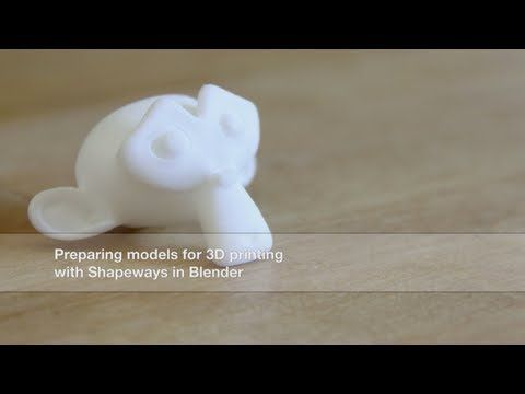 This is to say the outside geometry is something that can actually be 3D printed.
So, depending on your model, it may need some final touch-ups. This process is fairly simple, keep following along.
If your object is complex, there could be a chance that it isn't perfectly manifold. Let's check for that; follow these steps:
- Select the object you want to check.
- Press the N key to make the toolbar visible.
- Select the 3D Printing Toolbox section.
- Click on the Check All button.
- Take a look at the results, making sure that the Non-Manifold Edge displays a 0.
If so, then your model is ready to be exported as an STL file for your slicer software. But it may show a number above 0. Read on to fix this issue...
Fixing a Non-Manifold Model: Method 1
Let's start with the simplest way to fix a non-manifold model. We can use Blender's built-in cleanup tool. You can find it right next to the Check All button as seen in the previous section. There you will find a Clean Up section. Follow the below steps:
- Select your model.
- Open up the Clean Up section.
- Select Make Manifold.
This should also work on older versions of Blender. There is a slight disadvantage to this approach, in that it could possibly mess up your 3D model. If so, there is another method...
Fixing a Non-Manifold Model: Method 2
Instead of using Blender, we can use an external app called 3D Builder by Microsoft. It is available on Windows 8 and 10. After downloading and installing 3D Builder, open the program and import your model. Then, follow the below steps:
- Navigate to Open > Open Object.
- Navigate to your 3D Model wherever it is saved on your computer.
- Click on Import Model.
The 3D Builder software will tell you whether there are errors, with pop-up box notifications suggesting how you can fix them. After completing the prompted steps, the 3D model should now be manifold.
As a side note, when using 3D Builder, the model's shape may be changed in order to make it manifold. However, it is still much cleaner and these changes are normal to make it more printable.
4. Import Your Model to a Slicer
For the final step, we will need to export the model from Blender and import it into a slicer. A slicer is software that will convert the model into printing instructions for a 3D printer; this set of instructions is called Gcode. Specifically, it contains G and M commands, each with an assigned action.
In other words, it is the language used to tell the machine how to move parts or what pattern to follow in order to create the print. These instructions can also contain user-chosen parameters such as print speed and support structure; all this can be done in slicer software.
Before we can import the model into a slicer, we need to export it as an STL file. STL stands for "Standard Tessellation Language" or "Standard Triangle Language", and it describes the surface geometry of a 3D object. They cannot be printed in and of themselves. So let's go ahead and export the object as an STL file by navigating to File > Export > Stl (.stl) in Blender.
Then, import it into a slicing software, such as Cura. In Cura, you can simply drag and drop your model into it and the model will show up as seen in the above image.
Once you have your model in a slicer, you can go ahead and 3D print it. Be sure to check out our guide on the top Cura plugins that will make 3D printing more reliable and convenient.
Create Your Own 3D Printable Models in Blender
In this article, we've looked at how you can prepare your 3D model for printing in Blender. We also showed you a few ways to make your 3D model manifold, and then import it into a slicer program. Refer back to this guide if you want to make a model for 3D printing.
Blender 3D for 3D Printers / Sudo Null IT News
Correct position! But some problems can still be covered by polygonal modeling.
Gathered here the answers to the four most common and non-obvious problems.
Dimensions
When I first tried to order 3D printing from a company about seven years ago, it was like this:
— Igor! You sent an empty file!
- No! Here's a screenshot, well!
One meter in the Blender is equal to one millimeter in the slicer, nothing has changed in these seven years.
Designing in meters is wonderfully inconvenient, so when exporting to STL/OBJ, set the Scale value to 1000:
Closed geometry The ability to create open geometry is both a scourge and a bonus of polygonal modeling.
In the modern world, slicers (not all) have learned how to work with this, but there may be surprises: want a hole? get a blank wall!
If you don't like surprises, you should use Blender's geometry analyzer.
In mesh edit mode, select vertex selection, and click Select → Select All By Trail → Non Manifold
To eliminate such trash as on the right ball, there is a Merge By Distance tool. Lives in Mesh → Clean Up → Merge By Distance.
In other cases, it is necessary to either give the wall thickness by extruding, or close up the hole, or is this geometry really necessary?
And now for the good news: in Blender 2.8 the 3D printing addon is built right into Blender, hooray! Geometry analysis just got easier. You just need to turn it on, and in the edit mode in the N-panel everything will be (and even the preliminary volume of the model!).
Flying geometry
As unclosed, only flying. So the slicer can still try to shove it into the G-code!
The annoyance is that if the volume of the walls was made by a modifier, these mesh pieces can no longer be found with the Non Manifold tool.
Select any polygon on the target mesh, and use the Ctrl+L hotkey: it will add all physically connected polygons to the selection. After that, invert the selection with the Ctrl+I hotkey and delete everything you don't need.
Normals
Roughly speaking, the polygon has a "face". When the polygon enters the slicer, the slicer looks at where the polygon has a “face”, tries to fill the wrong side with plastic, and at the same time checks for overhangs.
Accordingly, a cube with normals inside will be perceived clumsily. In fairness, in modern slicers this is no longer so important.
The solution is super-simple: turn on the display of normals:
Flip in the right direction: select the polygon with the normal turned inside out and press Alt+N. Hoba! and the slicer no longer panics about negative angles where they cannot exist.
Generalize
Blender, indeed, is not developed as engineering software, and you should not try to solve furious tasks with it in the spirit of multicomponent kinematic systems.
But the blender + home 3D printer perfectly covers the needs of a small workshop, the main thing is to remember the nuances of polygonal modeling.
Preparing files for 3D printing in Blender
Share on Facebook Share on Twitter Share on Vkontakte
Look for open edges
If your 3D model consists of several objects or polygon meshes, the first thing you need to do is make sure that the edges of each part are closed, in other words, waterproof. To do this, you need to enter edit mode by pressing A (once to select any faces, twice to deselect), then you need to press the key combination ctrl-alt-shift-M (on Mac computers - ctrl-opt-shift- M).
After you press this key combination, all open faces will be selected. Often, to fix this error, you need to create a new surface with 3-4 faces (F key). Sometimes there are wandering edges that are either not attached to anything, or connected to only one edge vertex.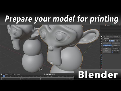 Often they can be safely removed, unless they were specially made. For example, these faces can be used to shape the model using the Subsurf modifier. In this case, you will need to apply this modifier first, and only then remove the unnecessary edges. In addition, do not forget about those open faces that are part of the intersecting surfaces.
If your model has 3-4 attached polygons that the software sees as open but says that a surface has been created, you need to delete that surface and try to recreate it. Moreover, inspect the edges of all those faces that were marked as open. Perhaps some of them are wrong: they do not belong to the polygon mesh or they are created in the wrong direction. In this case, you will have to delete this block and recreate it manually.
Tip: Hide the geometry to focus on the uncovered areas So, you can select not only open faces, but also the areas around them. Next press shift-H to hide the other faces. In this way, the closed parts of the model will be hidden, and it will be much easier for you to eliminate all the flaws.
Cleanup: Merge meshes using Booleans.
Once all the meshes are closed, make sure that each one represents a separate feature. You cannot apply boolean variables to polygon meshes that refer to the same object. At the same time, it is possible to split the meshes by selecting all its faces and pressing P. Next, select one vertex, then, holding ctrl, select all the others. To detach all polygon meshes of one object, press P and select the "All Loose Parts" option.
Once you've separated all the meshes into objects and made sure they're closed, save the project and save a copy of the blender file to create a printable version of it.
Open a copy of the file and select each object one at a time. In object mode, apply any modifiers you want. Next, go into edit mode by pressing the A key once or twice to select all the faces. Then press ctrl-T to triangulate all surfaces. It is not clear what this is connected with, but Blender works better with booleans if the meshes have been triangulated.
Return to object mode again, select 2 mutually intersecting meshes and press w. Then select the Union option, after which the meshes will be merged (this action does not delete the sources). The merging process may take some time. Once it completes, select the 2 original objects that were merged and either move them to another layer or delete them altogether.
Select the new, merged object, go to edit mode, deselect the edges (press the A key 1-2 times), then select the unclosed areas - ctrl-alt-shift-M. Fix these errors in edit mode, it will be pretty easy. Often, combining polygon meshes solves the problem of open areas, but not always. Therefore, we recommend that you still check your model. Otherwise, when further merging meshes that have open areas, you may have problems. Check it EVERY TIME. Then select all meshes and triangulate again. As a result, you will get a single mesh with closed faces that has been triangulated. Such a mesh is completely ready for further merging, if necessary.
If you have 2 meshes with incommensurable face density, such as when a rounded mesh is merged with a cube that has 8 vertices, subdivide the part with the fewest vertices. The mesh is then triangulated. For some reason Blender doesn't handle this kind of joins well. The process can take several hours, and it is not always possible to obtain the desired result.
Save every time after merging and only then eliminate uncovered areas.
Finish: Set your model size and export the file.
Once you have dealt with all the intersecting meshes and solved the problem of open areas, set your model to the desired size. Please note: 1 size unit in Blender is equal to 1 mm.
Check the status bar for the number of surfaces (it should look something like this: Fa:123456 - the number next to the Fa index is what you need). If you have more than 500,000 triangles, use the Polygon Reducer Script tool found in the Mesh - Script menu.