Best 3d print head
The 7 Best 3D Printer Hot Ends (All-Metal!) – Clever Creations
When it comes to 3D printing, the hot end is one of the most important components. It’s responsible for melting and extruding the filament, so it’s crucial that you have a good one.
In this article, we’ll discuss some of the best 3D printer hot ends on the market. We’ll also give you a few tips on how to choose the right one for your needs. So, without further ado, let’s get started!
| 3D Printer Hot End | Max. Temp | Filament Dia. | Voltage(s) | Price (~) | Best Offer |
|---|---|---|---|---|---|
| E3D V6 | 300 °C | 1.75 mm, 2.85 mm | 12V, 24V | $59 and up | Amazon |
| Micro Swiss All Metal Hotend Kit | 300 °C | 1.75 mm | 24V | $63 | MatterHackers |
| E3D RapidChange Revo | 300 °C | 1.75 mm | 12V, 24V | $88 and up | E3D |
| Slice Engineering Mosquito | 500 °C | 1. | 12V, 24V | $145 | MatterHackers |
| E3D Supervolcano Upgrade Kit | 300 °C | 1.75 mm, 2.85 mm | 12V, 24V | $96 and up | E3D |
| DyzEnd PRO | 500 °C | 1.75 mm | 12V, 24V | $130 | MatterHackers |
| Phaetus Dragonfly Hot End | 500 °C | 1.75 mm | 12V, 24V | $69 | BIQU |
What is the hot end in a 3D printer?
A hot end is the heating element in a 3D printer. It comprises several parts, including the heating element, nozzle, heat sink, and heat break.
The heating element is responsible for heating the filament to its melting point. The nozzle is a small hole through which the molten filament is extruded. And finally, the heat break limits the amount of heat that transfers to the heat sink.
These elements work together to provide an even flow of melted material and give you a smooth 3D printing experience.
What makes a good hot end?
The best 3D printer hot ends have good heat management, durability, material compatibility, and material flow rate. They minimize heat creep and maintain a stable printing temperature during extended 3D printing times. A stable hot end temperature reduces the chances of the hot end clogging up and prevents print failures.
A hot end with a high flow rate lets you print at faster print speeds and larger layer heights. This reduces print times and creates a strong 3D printed part.
Another aspect you need to consider is the material composition of the hot end. 3D printer hot ends with brass nozzles are not the best for printing with abrasive materials. Instead, you should look for hot ends with stainless steel or hard-coated nozzles. These nozzles are more wear-resistant and can handle abrasive materials better.
Similarly, if you want a hot end for 3D printing high temperature (>300°C) filaments, you are best off with a hot end with a copper-plated heater block, a high-powered heater cartridge, and a thermocouple. These hot ends can handle the higher temperatures required for printing with polycarbonate, PEEK, and other engineering-grade filaments.
The Best All-Metal 3D Printer Hot Ends in 2022
E3D V6
Best overall
Check Price
AmazonE3DMatterHackers
E3D manufactures some of the highest quality hot ends and the E3D V6 is one such example of that. It is simple yet effective and delivers excellent printing performance. It is suitable for both direct and Bowden drive extruders, and you can further customize it for your 3D printer directly through E3D’s website.
The E3D V6 is an all-metal hot end capable of reaching temperatures of up to 300 °C in the standard configuration. The cartridge-style heating block facilitates the easy removal of heater cartridges and thermistors for easy installation and maintenance. Its heatbreak is designed to maintain consistent and accurate temperature in longer prints.
As with all E3D products, the V6 has excellent community support, ensuring that you can quickly resolve any issues. Overall, it is a superb hot end that will take care of most of your printing needs and is suitable for hobbyists and professionals alike.
Standout Features
- All-metal heatbreak
- Cartridge style heating block
- Simple design
Technical Details | |
|---|---|
| Maximum temperature | 300 °C |
| Filament diameter | 1.75 mm, 2.85 mm |
| Available voltages | 12V, 24V |
What We Like
- Excellent printing performance
- Available in several configurations
- Excellent community support
Could Be Better
- Big form factor
Find E3D V6 at
AmazonE3DMatterHackers
Micro Swiss All Metal Hotend Kit
Best hot end for Ender 3
Check Price
AmazonMatterHackers
The Micro Swiss hot end is an upgraded version of the stock hot end for Creality 3D printers. You can install it directly on the default setup of CR-10 and Ender 3 series 3D printers without any extra mounting systems and brackets.
The Micro Swiss comes with a similar appearance to the stock Ender setup, albeit delivering improved performance. You get a titanium heat break that does an excellent job in thermally separating the hot and cold regions of the hot end resulting in a more defined melt zone.
You will need to recalibrate your retraction settings and ensure proper assembly of this hot end, however. Set it up correctly, and the Micro-swiss hot end is an excellent upgrade for anyone who wants to print high-temperature materials on a budget.
Standout Features
- Aluminum heater block
- Titanium heat break
- Brass plated MK8 nozzle
Technical Details | |
|---|---|
| Maximum temperature | 300 °C |
| Filament diameter | 1. 75 mm 75 mm |
| Available voltages | 24V |
What We Like
- Easy to use with Creality printers
- Good build quality
- Good customer support
Could Be Better
- Requires tweaking
- Potential retraction and leakage issues
Find Micro Swiss All Metal Hotend Kit at
AmazonMatterHackers
E3D RapidChange Revo
Best high-end
Check Price
E3DMatterHackers
Swapping out a 3D printer nozzle can be a labor-intensive process and result in significant downtimes in your 3D printing process. To speed this process up, the E3D Rapid Change Revo comes with a unique design that lets you quickly change your nozzles without any tools.
It features a design similar to the E3D V6 hot end but in a more compact and lightweight form factor. The hot end comes with a redesigned heating block that is engineered for safety and maximum heating performance. The Revo is compatible with most high-temperature materials and delivers superb print quality out of the box.
You can get the hot end in three configurations – Revo Micro, Revo Six, and the Revo Hemera. Each version is developed for different use cases. Together, the Revo Rapid change system covers a wide range of 3D printing applications.
A RapidChange Revo hot end is well-suited for professional users who are looking for the best hot ends with easy maintenance.
Standout Features
- Quick-swappable nozzles
- Lightweight design
- Fast heating times
Technical Details | |
|---|---|
| Maximum temperature | 300 °C |
| Filament diameter | 1.75 mm |
| Available voltages | 12V, 24V |
What We Like
- Compact form factor
- Faster print speeds
- Easy maintenance
Could Be Better
- Limited nozzle options
- Pricy nozzles
- Not compatible with 2.
 85 mm filament
Find E3D RapidChange Revo at
E3DMatterHackers
Slice Engineering Mosquito
Best for high-temperature filaments
Check Price
AmazonMatterHackers
The Slice Mosquito hot end comes with a unique design that separates it from other hot ends. The heater block is entirely separated from the frame of the hot end with the help of four support rods. It helps to eliminate heat creep and improves thermal performance.
This design allows the hot end to be highly compact and lightweight, resulting in extra vertical height and faster print speeds. Its rigid construction allows for one-handed nozzle changes making maintenance an easy task.
In contrast to the previously mentioned hot ends, the Slice Mosquito is rated to print at high temperatures of up to 500 °C, covering filaments such as PEEK, ULTEM, and PPSU.
At a starting price point of $144.99, it is certainly not for budget 3D printer users. However, the Slice Engineering Mosquito hot end is ideal for professionals who need a high-performance hot end that delivers excellent print quality and broad material compatibility.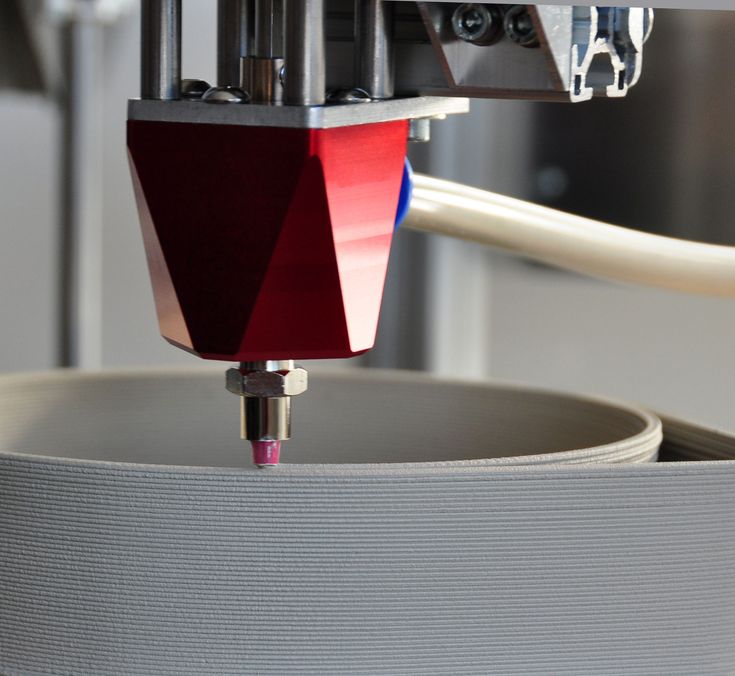
Standout Features
- Unique design
- High printing temperatures
- High structural rigidity
Technical Details | |
|---|---|
| Maximum temperature | 500 °C |
| Filament diameter | 1.75 mm |
| Available voltages | 12V, 24V |
What We Like
- Lightweight and compact design
- No heat creep
- Compatible with majority of FDM 3D printers
Could Be Better
- No liquid cooling option
Find Slice Engineering Mosquito at
AmazonMatterHackers
E3D Supervolcano Upgrade Kit
Best for large 3D printers
Check Price
AmazonE3DMatterHackers
The E3D Supervolcano upgrade kit is specifically designed for fast printing of large objects. It delivers up to 11x more volumetric flow rate than regular E3D V6 hot ends.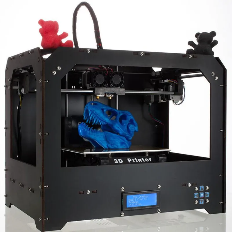 This lets you 3D print at higher speeds with large layer heights and widths.
Wider layers allow for better interlayer adhesion resulting in a stronger 3D printed part. While 3D print strength is something you can also increase by choosing the strongest infill pattern and strongest filament, printing wider layers gives you another option to do so.
The Supervolcano can reach a maximum print temperature of 300 °C, letting you print with materials like PLA, ABS, PETG, and TPU. It is fully compatible with various other E3D hot ends and extruders, so you can easily upgrade your default setup to a Supervolcano.
This is the best 3D printer hot end for a large format 3D printer to carry out high-volume printing. If your printing workflow consists of large-scale and high-volume 3D printed parts, the Supervolcano kit is crucial in reducing your 3D printing times.
Standout Features
- 11x volumetric flow rate (compared to V6)
- Copper plated heat break
- Readily compatible with E3D hot ends
Technical Details | |
|---|---|
| Maximum temperature | 300 °C |
| Filament diameter | 1. 75 mm, 2.85 mm 75 mm, 2.85 mm |
| Available voltages | 12V, 24V |
What We Like
- High filament melting rate
- Suitable for large objects
- Option for second thermistor
Could Be Better
- Reduces print height
- Increased chances of thermal runaway and safety issues
Find E3D Supervolcano Upgrade Kit at
AmazonE3DMatterHackers
DyzEnd PRO
Most durable nozzle
Check Price
MatterHackers
The DyzEnd Pro hot end is a high-performance hot end developed for a professional workflow. It comes in a lightweight and compact design that takes up less space.
This hot end comes with a tungsten carbide nozzle with excellent wear resistance. This means you can use the DyzEnd PRO for 3D printing abrasive materials, like carbon fiber or glow-in-the-dark filament, without fear of it wearing out.
Its all-metal heat zone and steel heater block ensure that you can print materials up to 500°C with ease.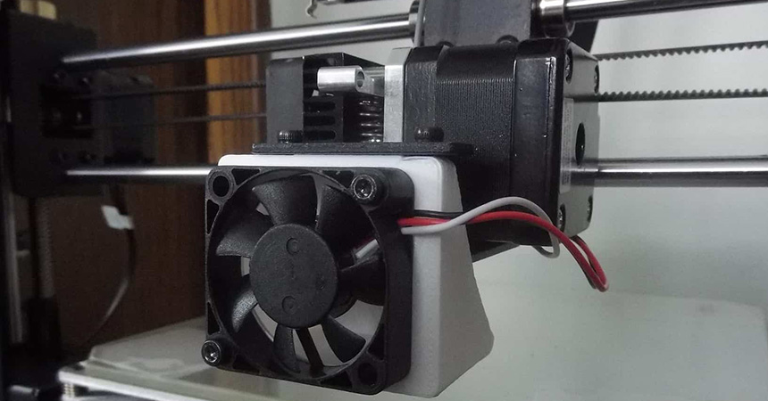 You can also quickly cold swap the nozzle on the DyzEnd Pro for less downtime and easy repairability.
It is a superb hot end meant for serious professionals who regularly print with high-temperature materials. If you’re looking for a lightweight, robust and good quality hot end for your 3D printing workflow, the DyzEnd Pro is one of the best hot ends available.
Standout Features
- Cold swappable nozzle design
- High maximum temperature
- Liquid cooling ready
Technical Details | |
|---|---|
| Maximum temperature | 500 °C |
| Filament diameter | 1.75 mm |
| Available voltages | 12V, 24V |
What We Like
- Fast printing speeds
- Increased durability with abrasive filaments
- Compatible with different temperature sensors
Could Be Better
- Limited nozzle sizes
- Requires considerable fine-tuning
Find DyzEnd PRO at
MatterHackers
Phaetus Dragonfly Hot End
Check Price
AmazonBIQU
The Phaetus Dragonfly hot end is an all-metal hot end designed for hobbyists and professionals.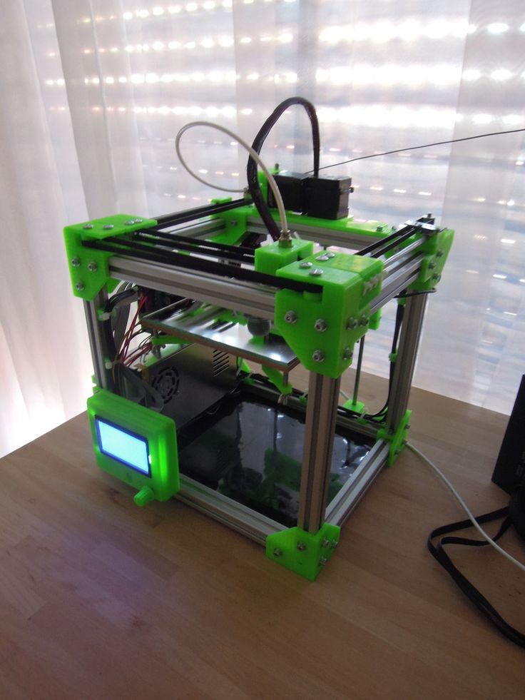 It uses copper alloy material for its heat sink for better heat dissipation. The Dragonfly also lets you print at up to 500 °C, making it one of the cheaper 3D printer hotends that can reach these high temperatures.
This hotend has a smooth inner surface that aids in getting an uninterrupted filament flow. Its conical heat break designs allow fast heat dissipation, maintaining good thermal separation and a stable melt zone.
Compared to the other hot ends that can reach 500 °C on this list, the Dragonfly is reported to come with more quality control issues. This is something that can be expected given its low price but it is still something we think you should be aware of.
The Dragonfly Hot end comes in two variations suitable for Creality and Prusa 3D printers. It is ideal for individuals who need a high-temperature hot end that’s easy to use and comes at a budget price.
Standout Features
- All-metal design
- Conical heat break
- Copper alloy construction
Technical Details | |
|---|---|
| Maximum temperature | 500 °C |
| Filament diameter | 1. 75 mm 75 mm |
| Available voltages | 12V, 24V |
What We Like
- Excellent heat dissipation
- High printing temperature
- Relatively low price
Could Be Better
- Quality control issues
- Inconsistent printing performance
Find Phaetus Dragonfly Hot End at
AmazonBIQU
Buyer’s Guide – How to Choose a 3D Printer Hot End
3D Printer CompatibilityHot ends are not a generic component and are often designed for a specific set of 3D printers. Checking the hot end’s compatibility with your 3D printer is essential for getting the best results. It will ensure that you get the right hot end that supports your 3D printer’s hardware and electronics.
One of the things to look for is the heater cartridge voltage on the hot end. It has to match the printer’s voltage to ensure proper heating of the hot end.
You also need a mounting system for the hotend. Any additional mounting plates and hardware will translate to an increase in the cost, even though you can 3D print these yourself sometimes.
Material Compatibility
A hot end with wide material compatibility is always a good thing to have. This allows you to experiment with different materials and find the ones that work best for your needs.
The most important thing to look for is the maximum temperature that the hot end can reach. This number will give you a good idea of the range of materials that the hot end can work with.
Typical all-metal hot ends can reach up to 300 °C and can easily print most thermoplastics. This range covers PLA, ABS, PETG, Nylon, and flexible filaments like TPU and TPE.
If you need to print high-performance plastics such as PEEK, ULTEM, Polycarbonate, and PEI, you will need a hot end that has a maximum printing temperature of 500 °C.
High-performance hot ends will be more expensive than the basic ones and might not yield good results when printing at lower temperatures. If you primarily print with materials that melt below the 300 °C points, basic all-metal hot ends like the E3D V6 and the Microswiss should be enough for you.
Nozzle Compatibility
A nozzle is an important component of the hot end assembly. Nozzles are designed with their hot end’s specifications in mind. The nozzle you use defines the printing capability and material compatibility of your hot end.
A larger nozzle size will let you print fast and with large layers, while a fine nozzle is suitable for printing detailed parts. Both can be properties to look for when looking to make money with your 3D printer.
Similarly, a nozzle’s material will also affect the print quality. Nozzles made from stainless steel can handle higher temperatures and are more wear-resistant. As a result, they can last longer, but they might not be the best choice for printing with PLA.
On the other hand, brass nozzles are a good all-around choice and can be used with most materials. If you are unsure about the material of the nozzle, always check with the hot end’s manufacturer.
Due to the hot end’s design, nozzles aren’t interchangeable between 3D printer hot ends from different brands. For example, the DyzEnd nozzle is specific to the DyzEnd Pro hot end. Similarly, the E3D Supervolcano exclusively supports E3D nozzles of sizes 0.6 mm – 1.2 mm.
If you 3D print with parts of varying layer heights and with different materials, you need to ensure that you get a hot end that’s compatible with various nozzle sizes and materials.
Build Quality
A hot end is the critical component of the 3D printer and is responsible for extruding the filament smoothly. A poorly manufactured hot end will lead to many issues down the line.
Nozzle clogs, hot end jamming, filament leakage, and improper filament flow all indicate poor hot end build quality. These issues can be frustrating and time-consuming to deal with. Checking the user reviews before you purchase the hot end will give you a better idea about its build quality.
Cheaper hot ends tend to have poor overall quality and while they might work well in the beginning, they can experience many issues after prolonged use.On the other hand, a well-manufactured hot end will have a high upfront cost and give you consistent printing performance and a high-quality experience.
Should You Buy an All-Metal Hotend or Not?
All-metal hot ends are helpful for printing materials like ABS, PETG, and Nylon. Where PTFE-lined hotends are only suitable for printing up to around 250°C, an all-metal hot end typically reaches temperatures of either 300°C or 500°C
These temperatures are more than enough for printing a wider variety of materials. The all-metal design also eliminates the need to replace the PTFE liner in the hotend over time, as the PTFE tube is no longer exposed to extreme temperatures.
However, the all-metal design can create more filament jamming issues when not configured correctly. A shorter retraction distance helps to minimize stringing and consequently prevent filament jams, however.
If you plan on printing with a lot of different materials or if you want to experiment with higher temperatures, an all-metal hot end is a good investment. Otherwise, a PTFE-lined hot end will suffice for most applications.
That said, you can’t ever go wrong with an all-metal hotend upgrade. If you simply want the best 3D printer hot end for your machine, all-metal is the way to go.
FAQ
When should I replace my 3D printer hot end?
There’s no need to replace your 3D printer hot end unless you’re looking for an upgrade to get better performance. You might have to periodically replace certain components, like the nozzle, when they wear out, however.
If you are experiencing issues with your prints, then it may be time to check your hot end for any damage or debris that may be causing problems.
Is an all-metal hot end good for PLA?
Yes. While all-metal hotends are ideal for higher-temperature filaments, they can also be used with lower-temperature filaments like PLA. Some users find that they get better results using an all-metal hotend with PLA than they do with a standard hotend with PTFE lining.
What type of hotend does the Ender 3 use?
The Ender 3 uses a PTFE-lined hot end, which allows for smoother filament flow and reduced clogging. PTFE is a low-friction material that is resistant to wear and tear, making it an ideal choice for a hot end.
If you want to upgrade your Ender 3 hot end, the Microswiss is one of the best hot ends to swap the stock one out with.
Which hot end is best?
In our opinion, the E3D V6 hotend is currently the overall best hot end on the market. It is made of high-quality materials and has a modular design that makes it easy to assemble and maintain. It also has a wide range of compatibility with different types of printers, making it a popular choice for both beginners and experienced users.
Conclusion
Choosing the right hot end for your 3D printer will extend your printing potential. The best 3D printer hot end minimizes heat creep while maintaining a stable printing temperature. However, you need to check that the hot end you select fits your 3D printing needs and is compatible with your 3D printer.
The E3D V6 hot end ranks on the top as the best 3D printer hot end. It is one of the most reliable hotends that has been well-tested over the years and is suitable with a good of materials. It has an all-metal design, broad 3D printer compatibility, and excellent build quality at a reasonable price.
Its only drawback is its limited range of printing materials. With a maximum temperature of 300°C, it won’t handle true engineering materials like PEEK.
This is where the Slice Engineering Mosquito and the DyzEnd Pro hot end step in. These are rated to print up to 500 °C and come with unique designs with elegant features.
So, what is the best 3D printer hot end for you? It depends on your specific needs. Consider the type of materials you want to print with, your budget, and your 3D printer compatibility when making your decision.
Let us know your experience if you’ve used any of these hot ends. We’d love to hear if you have anything else to add in the comments below.
Best 3D Printer Hotends & All-Metal Hotends to Get – 3D Printerly
In your 3D printer, several parts perform functions to make sure the printer runs smoothly. Arguably, the most important component of all of is the hotend.
Why? The hotend is the part that melts the filament into thin straight lines and deposits it on the print bed. It affects everything from the printing temperature to the speed to even the quality of the printed object.
So, to get the best out of your 3D printer, it’s a great idea to invest in a quality hot end.
In this article, I’m going to help you do just that. I have put together a list of some of the best 3D printer hotends on the market. I also added some of the things to look for before buying.
Using our criteria, I’ve checked out the all-metal hot ends available on the market. After evaluating them, I’ve come up with a list of the six best all-metal hotends.
Price: Around $60 | Material: Aluminum (Cooling block, Heat block), Titanium (Heat break) | Temperature Range: 260°C+ | Compatibility: Creality printers / 1.75mm filament
The Micro Swiss all-metal Hotend kit is an excellent replacement for non-metal parts stock hot end. It is built with premium materials like titanium and aluminum to ensure top-notch service and little wear.
Furthermore, it is also easy to install, requiring no modification at all to the firmware.
The Micro Swiss Hotend comes with aluminum cooling and heating blocks, a brass-plated wear-resistant nozzle, and a Grade 5 titanium heat break. The nozzle is replaceable, and the printer supports nozzle sizes from 0.2mm to 1.2mm.
The titanium heat break is where this hot end shines. Titanium offers up to three times less thermal conductivity than conventional stainless steel. It helps the hotend in creating a more defined melt zone.
It is said that this hotend can hit temperatures of 260°C without any changes, then it requires a firmware flash by changing the configuration.h file to reach higher temperatures, but you only want to do this if your printer has the capabilities.
Some have mentioned that low-cost 3D printers have the bare minimum when it comes to the wiring and the circuit which can overload in some cases.
The hotend circuitry should be the same as the heated bed circuitry which draws a lot more power, so the power to the hotend should be safer, as long as the wires are up to par.
Another thing to keep in mind is how the accuracy of your thermistor reduces as you go into those higher temperatures, but for most materials, you don’t need to go so high regardless.
Even for Polycarbonate, you can get low temperature versions like the Easy PC CPE Filament from Filament.ca that requires around 240-260°C and a bed of 95°C.
User Experience
The Micro Swiss hotend is easy to install and even comes with tools in the box for that. Its superior build quality and ease of installation have already made it a favorite of users.
There is no need for firmware modifications to make it work. The hotend is plug-and-play. Many users describe this as an excellent piece of kit which provides amazing results from day 1.
One user who had clogging issues with their Ender 5 Pro tried many solutions to no avail. Once they bit the bullet and got themselves the Micro-Swiss All-Metal Hotend Kit, they could finally print without problems.
The Hotend itself feels like a premium product which is fairly expensive, but the results show how worthy it is.
Another user described it as a “first class upgrade for my Ender 3 Pro” due to having a significant improvement on their 3D prints.
If you are experiencing issues like heat-creep, many people have solved it by getting themseves this hotend.
Some people have complained about a leaking nozzle or heat creep, but this usually comes down to not following the right installation instructions.
To reduce clogging, Micro-Swiss say to have a maximum retraction of 1.5mm at 35mm/s.
Pros of the Micro Swiss All-Metal Hotend Kit
- Comes with a wear-resistant nozzle.
- Can print high-temperature materials.
- Doesn’t require a heat tube replacement.
Cons of the Micro Swiss All-Metal Hotend Kit
- Tends to clog when printing with low-temperature filaments.
- There have been reports of nozzle leakage.
- It’s a bit expensive considering electronics aren’t in the box.
Final Thoughts
The Micro Swiss all-metal hot end ticks all the right boxes when it comes to design and materials. But when buying such a premium hotend, the issues and long-term viability should give any buyer pause.
If you want to transform your 3D printing experience, whether on your Ender 3, Ender 5, or other compatible 3D printer, get yourself the Micro-Swiss All-Metal Hotend Kit today.
Price: Around $60 | Material: Aluminum (Cooling block, Heating block), Stainless Steel (Heating break) | Temperature range: 300°C | Compatibility: Almost all printers / 1. 75mm & 3.0mm filaments
The E3D V6 all-metal hot end is the gold standard for all-metal hotends in 3D printing. Its reliability and versatility have made it a favorite among 3D printing enthusiasts for years.
It’s used widely in 3D printing with various printers and materials.
Another reason this hot end is so popular is its modularity. The E3D V6 comes with an extensive support ecosystem of different parts for different printing scenarios. You can easily swap out parts and configure the hot end for any printing scenario.
The E3D V6 is a machined metal build. It comes with an Aluminum heat sink and heater block break. The Heat break, however, is made out of stainless steel. The nozzle is made out of brass, but it can be easily replaced with a wide variety of options.
It can be fit on many 3D printers, but in some cases, you’ll need a modification and a mount for 3D printers like the Creality CR-6 SE and Di Vinci Pro 1.0. There are plenty of custom carriages you can find on Thingiverse for your 3D printer.
The kit itself comes with many separate parts that you put together:
Metal parts
- 1 x Aluminium Heatsink (Contains brass embedded bowden coupling ring pre-fitted in top)
- 1 x Stainless Steel Heatbreak
- 1 x Brass Nozzle (0.4mm)
- 1 x Aluminium Heater Block
Electronics
- 1 x 100K Semitec NTC thermistor
- 1 x 24v Heater Cartridge
- 1 x 24v 30x30x10mm fan
- 1 x High Temperature Fiberglass Wire – for Thermistor (150mm)
- 2 x 0.75mm Ferrules – for Solder-Free Wire Joins
Fixings
- 4 x Plastfast 30 3.0 x 16 screws to attach the fan to the fan duct
- 1 x M3x3 socket dome screw and M3 washer to clamp thermistor
- 1 x M3x10 socket dome screw to clamp the heater block around the heater cartridge
- 1 x Fan Duct (Injection Moulded PC)
User Experience
The E3D V6 All-Metal Hotend is a genuinely great hot end. It can be a little tricky to set up for first time users, but there are plenty of resources online for help.
To install, all you have to do is find the correct mounting for your printer on Thingiverse and follow directions.
However, for some unsupported printers, there still have to be some additional firmware modifications for the hot end to function properly.
This isn’t a deal-breaker as thermistors are replaceable.
One user who implemented this hotend and used it for around 50 hours said that it’s the best money they spent on their 3D printer. Since installing it, they haven’t had a single clog while using materials like PLA, ABS, and PETG.
There are a few reviews where the kit came with a faulty thermistor, but this can easily be replaced through their customer service or getting a set of your own.
Pros
- A great ecosystem of parts
- Superior build quality
Cons
- It has a complex installation process for some printers.
- There have been problems with its thermistors after delivery.
Final Thoughts
This hotend is hands down one of the best in its class. It combines effective design with a decent price, you’d be hard-pressed to find one with as much accessory support as this.
Get yourself the E3D V6 All-Metal Hotend from Amazon today.
Price: Around $140 | Material: Aluminum (Cooling block, Heating block), Stainless Steel (Heating break) | Temperature Range: 300°C | Compatibility: Almost all printers / 1.75mm & 3.0mm filaments
The E3D titan aero differs from all the hot ends on this list in the sense that it’s technically an extruder – hot end combo. It combines the design of the E3D V6 hot end with a Titan extruder to create a smaller, more compact extrusion system.
It’s a Direct Drive setup which means it has a much shorter filament path than Bowden, leading to less jamming or bending. This is perfect for flexible filaments or simply improving the quality of normal filament in many cases.
The Titan Aero’s compact design means it occupies less space than standard hotend/extruder combinations.
This design means it takes up less build volume on the Z-axis.
The Titan Aero is built on the bones of the E3D V6 system, so this means it inherits the modularity of the previous system. Most of the aftermarket accessories compatible with both the V6 hotend and the Titan extruder should work with it.
One of the key attributes of this extruder is how lightweight, reliable, and versatile it is performance-wise. It has the Titan 3:1 gearing ratio along with the compact and poweful motor, for low weight and pushing power.
User Experience
The Titan comes with quite a bit of assembly required. There are videos and resources available online to guide users through the installation process.
Even with these resources, the process can be a little complex for inexperienced users.
The stock materials in the Titan limit the maximum printing temperatures. To print at higher temperatures with better materials, you’ll have to swap out these components.
As you may know, there are many knockoff versions of different 3D printers, and even hotends. One user had an E3D V6 knockoff and then changed over to the real thing, which led them to noticing a “tremendous difference in print quality”.
One user who has a 3D printing service implemented this in their operation and found it to be a great addition to print plenty of hours throughout the day.
The pankcake stepper motor is nice and compact, but you can even go with a Genuine E3D Slimline Motor to get an even more compact stepper.
Depending on what 3D printer you have, you can find an applicable mount on Thingiverse, which you’ll want to print out of ABS or PETG for the higher heat resistance.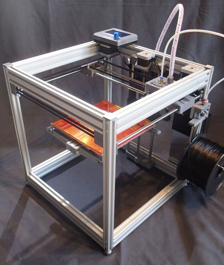
Pros of the E3D Titan Aero
- Great space-saving design.
- Has a wide selection of accessories.
Cons of the E3D Titan Aero
- It is expensive.
- Assembly can be a bit complicated.
Final Thoughts
The Titan Aero offers a proven high-quality extruder and hotend design in a compact package. If you’re looking to revamp your extruder setup, this is the one for you.
But, if you’re already using a Titan extruder or a V6 nozzle, then this upgrade might not change much for you.
Get the E3D Titan Aero from Amazon.
Price: Around $85 | Material: High Strength Copper, Hardened Steel and Brass Alloy | Temperature Range: 500°C | Compatibility: All printers compatible with V6 / 1.75mm Filaments
The Phaetus Dragon is a premium all-metal hot end made for printing at high temperatures. It provides efficient thermal performance with consistent filament flow at high speeds.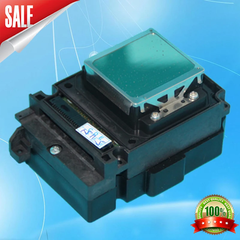
This is due to the insulation provided by its heat break and the low inner roughness of its nozzle.
The Phaetus Dragon diverges from conventional hot end design by connecting the heat block to the heat sink with four stainless steel tubes. The heat transfer between these parts is lowered considerably with this design.
It also gives the hot end additional structural rigidity, which makes one-handed nozzle changes possible.
Nozzle replacement is made easier due to the internal frame structure, so it can be done without needing to hold the heat block.
User Experience
Setting up the Phaetus Dragon is very easy due to its compact design. Although the Phaetus Dragon does not come with electronic parts in the box, it’s compatible with accessories used for the V6.
During printing, the hotend performs as advertised, spitting out filament consistently at high temperatures. However, users have reported clogging issues on the hot end. The clogging issues have been attributed to the improper mounting of the hotend.
Despite all these, when it comes to print quality, the Dragon consistently produces high-quality results.
If you do use a temperature of above 250°C for a long time, you’ll want to take the silicone sock off the hotend to prevent damage.
Pros of the Phaetus Dragon Hotend
- Fast heating and heat dissipation due to the copper build.
- High filament flow rate.
- High-temperature resistance.
Cons of the Phaetus Dragon Hotend
- Electronics do not come in the box.
- It clogs when printing with some materials.
- It is expensive.
Final Thoughts
The Dragon hotend is one of the best hotends on the market right now. If you’re looking for top-quality thermal performance at high printing speeds, then this hotend is for you.
You can find the Phaetus Dragon Hotend from Amazon.
Price: Around $160| Material: Copper Alloy (Heater Block), Copper Heat sink), Stainless Steel (Heat Break) | Temperature range: 450°C | Compatibility: Almost all printers / 1.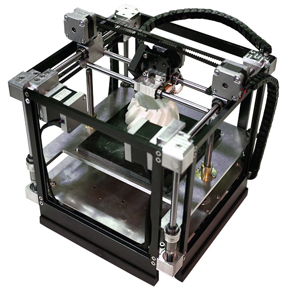 75mm Filaments
The Mosquito Hotend is one of the more modern products on this list, but it is already proving to be one of the best.
It brings a new radical hot end design to the table. Instead of the traditional heat break, it builds everything off a single metal frame.
This gives it thermal and mechanical advantages over conventional hotends.
Why is this important? Since the heat break isn’t required to connect the parts, a more efficient copper heat sink can replace the traditional stainless steel heat break. It also makes installation easier since there are fewer parts.
Compared to a normal hotend, the heat break conducts 85% less heat into the heat sink compared to a normal heat break. You don’t need a large heat sink due to the reduction in heat transmission.
Also, with fewer moving parts in a compact design like that, the durability is increased.
It is an adaptable piece of kit that has four different mounting options, machined adapters, and plenty of options to mount to the 3D printer of your choice.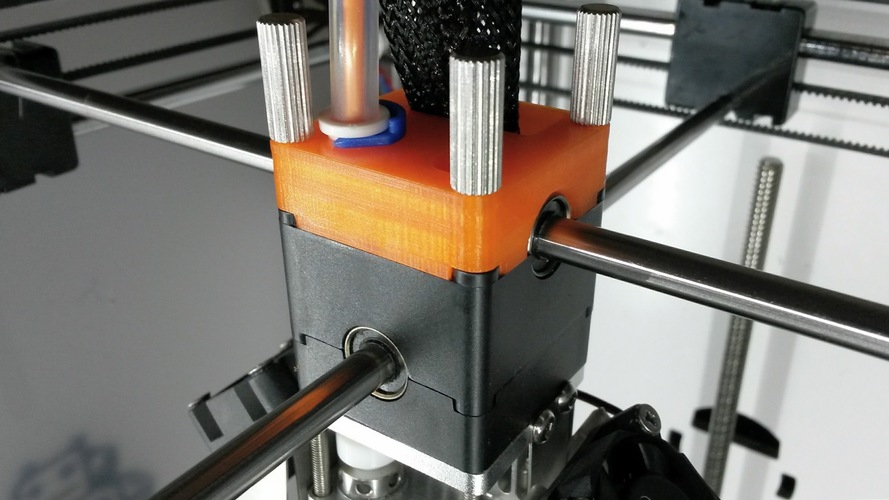 You’ll find adapters on Thingiverse as usual.
They say how it’s especially ideal for 3D printers that support multi-extrusion setups.
When you get the Mosquito Hotend, it comes as a package:
- Mosquito Magnum Hotend
- Cooling Fan – 12v
- Mounting Kit – 9 screws, 2 washers, zip-tie
- 3 Hex Keys
Installing the Mosquito Hotend is very easy due to its design. You’ll need to get a special adapter if your printer’s mount is not supported. It’s as close as you can get to an actual plug-and-play hotend.
Replacing parts like the nozzle is even easier as you can do them one-handed.
Getting new accessories for the Mosquito hot end is no problem, as the hotend is compatible with the V6 range of products. When it comes to print quality, the mosquito hot end is no slouch.
It churns out great quality prints at elevated temperatures justifying its price tag.
Pros of the Mosquito Hotend
- Great design
- Wide range of compatible accessories
- High printing temperature range
Cons of the Mosquito Hotend
- Fairly expensive
- It does not come with electronics in the box
Final Thoughts
The Mosquito Hotend brings a new game-changing design built with top-notch materials to create a great product.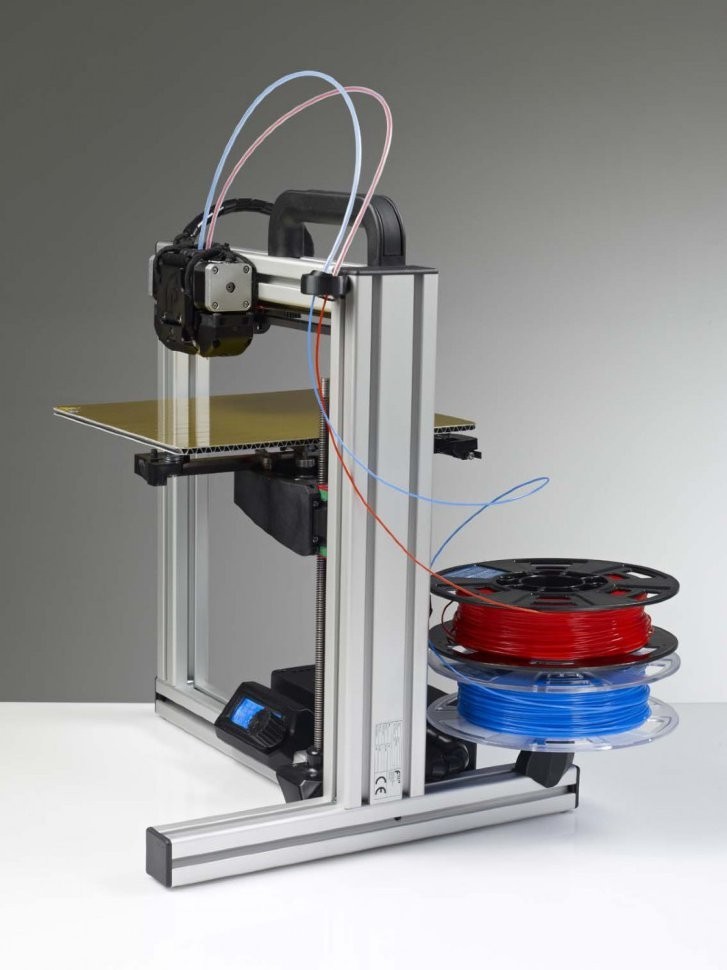 It might be a little costly for some, but if you’re looking to upgrade to the best, then it doesn’t get any better than this.
Check out the Mosquito Hotend on Amazon for a real improvement in your 3D printing.
Price: Around $25 | Material: Aluminum, Stainless Steel, and Brass | Temperature Range: 260°C | Compatibility: Select Creality Printers. / 1.75mm Filaments
The Sovol Creality hotend is a budget option for those looking to replace their stock hot ends cheaply. It comes with a fully assembled hotend extruder array and 0.4mm nozzles. This is one of the cheapest all-metal hot ends on the market.
You’ll probably find this to be one of the most popular hotends out there due to it’s price, effective output, and ease of use.
This happens to a 100% Creality Original, where they have silver and golden versions. It comes with the top quality Capricorn PTFE tubing which has good lubricity, as well as high temperature resistance so it won’t give up on you so easily.
Many people have seen 3D print quality improvements just from the PTFE tubing alone.
This hotend kit is very easy to plug into your 3D printer.
User Experience
The hotend comes fully assembled with a threaded connection for easy installation.
The experience with the Sovol Creality Hotend are mostly positive, with one user stating how they had some feeding and retraction issues with their Ender 3 Pro. Once they installed the new hotend with the PTFE tubing, they got great results.
It’s a pretty standard replacement for your Creality 3D printers, and you can expect grat performance like thousands of other users sout there.
When it comes to the thermal performance, this hot end performs how you’d expect a budget hotend to, poorly. The print temperature maxes out around 260℃. This makes it unsuitable for high-temperature applications.
Some users have complained about getting substandard products different from the specifications shown, so be careful to get yours from a trusted vendor.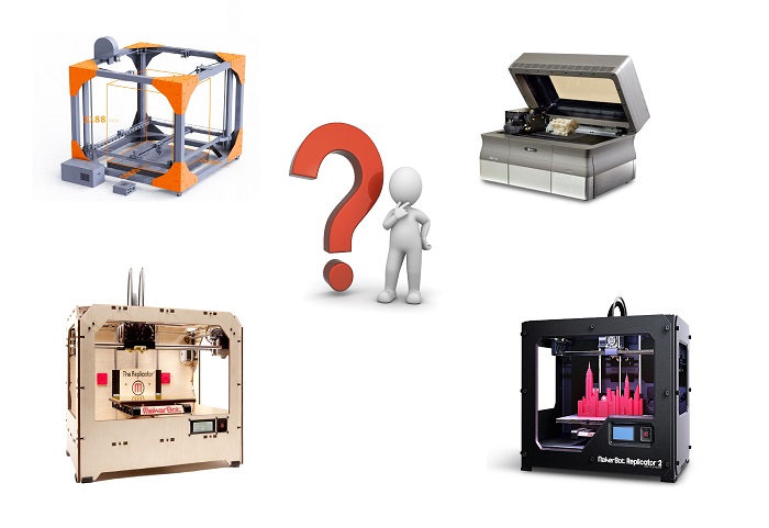
Make sure that you have the right voltage for your unit since it is a 24V unit. If you run into some issues where your 3D printer doesn’t heat up as well, check your power supply and your controller.
If your power supply is set to run at 220V, people say changing it to the 110V input gets it working as it should. In terms of the controller, you won’t get the right heating if you have a 12V controller, so check your power supply is 12V.
Pros of the Sovol Creality Extruder Hotend
- Comes with its electronics in the box.
- It is cheap.
- Comes fully assembled
- Easy to install into your 3D printer
Cons of the Sovol Creality Extruder Hotend
- The printing temperature range is low compared to other hotends
Final Thoughts
If you’re looking for a hot end to replace or upgrade what you have without breaking the bank, then this is for you. Just beware, you get what you pay for, nothing more and a little bit less.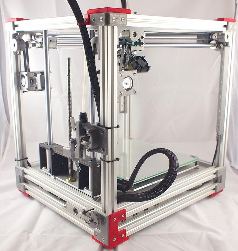
Hotend Buying Guide
Quality hot ends can seriously change your printing activities for the better, but they can also be costly.
With an increasing amount of clones of famous brands on the market, it’s best to know what to look out for to avoid wasting money on substandard products.
To help in making your purchase decisions, let’s look at some of the things that make up a quality hot end:
Material And Build Quality
The type of materials used in the construction of the hot end is very important. It determines the mechanical properties of the hot end like durability, wear-resistance, and thermal conductivity.
The material can also influence the type of filaments used and the maximum print temperature.
When discussing materials, there are two main camps – All metal and PTFE hot ends. In this article, there is more of a focus on All-Metals hot ends. All-metal hotends can be built from brass, steel, or even aluminum.
The build quality is also a crucial property.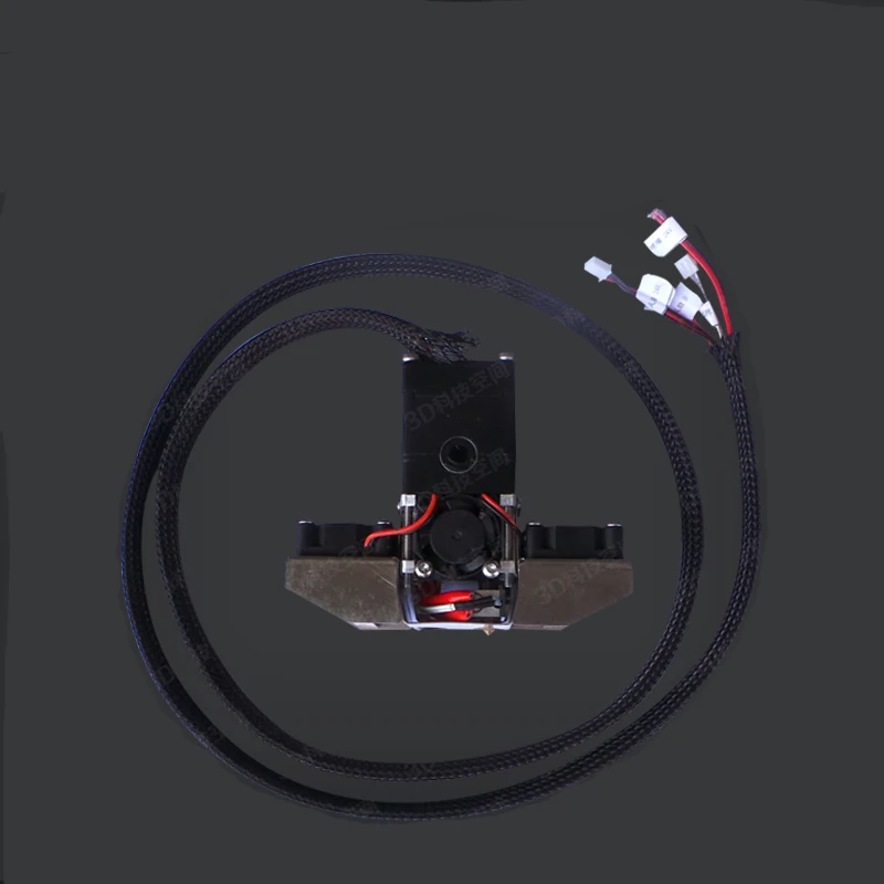 Machined hot ends with modular, simple, and compact designs often fare better since there are fewer moving parts. They rarely suffer from flaws like clogs or creep because of their design.
Temperature
The print temperature required is also a factor to consider when picking a hot end. When printing materials that need high temperatures like PEEK, it’s best to go for sturdier all-metal hotends.
These hot ends can resist the thermal stresses encountered efficiently.
Accessories
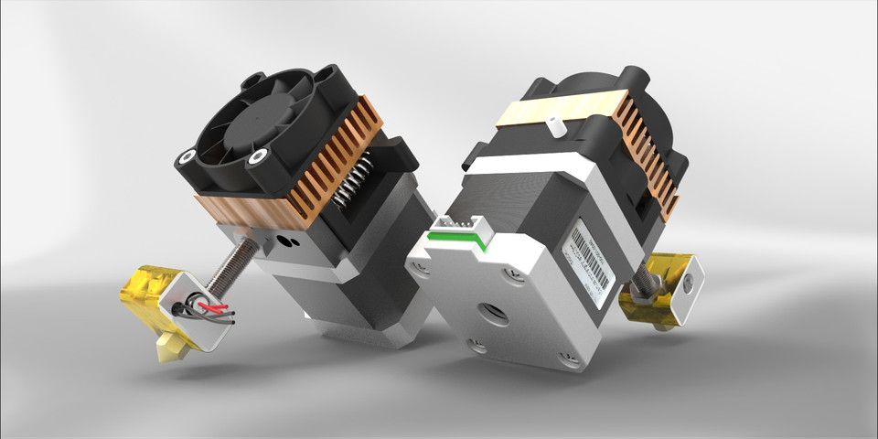
Accessories cover all the functioning parts of the hot end ranging from the heating block to the nozzle. For the best results, it’s best to use hotends with a modular design. You can change components on these hotends as the situation requires.
These accessories include nozzles, thermistors, etc.
Also, with components like heater cartridges and thermal probes that fail frequently, the importance of quality accessories cannot be understated. If they fail, it’s crucial to know you can easily find replacements.
Compatibility
All hotends are not universally compatible with all printers. There are usually differences that pop up due to differences in firmware, printer configuration, etc.
A mark of a good hotend is it is compatible with a wide range of printers without requiring much in the way of modifications.
Tips For Buying A Great All-Metal Hotend
Factoring in all the advice given above, I’ve come up with some tips to help guide you when purchasing your hot end. These tips are a checklist of sorts to follow before making a decision.
Let’s take a look at them:
- Always double check to see if the nozzle is compatible with your 3D printer.
- If there are a lot of knockoffs, then the hot end is a great product. Just be careful not to buy a fake.
- Always check if the hot end you are using can handle the material you want to use. Not all hotends can handle abrasive, flexible, or high-temperature filaments.
- When printing for food or medical applications, never get a brass nozzle.
 Stick with non-toxic metals like steel or aluminum.
Advantages And Disadvantages of All-Metal Hotends
Earlier in the article, I mentioned that there are many types of hotends like all-metal, PTFE, and PEEK. But throughout this list, I’ve focused on all-metal hotends to the detriment of all others.
This is because all-metal hotends offer certain advantages that other brands do not. Let’s take a look at some of these advantages:
- All-metal hotends can print at higher temperatures.
- They can handle a wider range of filaments better.
- The PTFE liner no longer has to be replaced regularly.
Although all metal hotends are better performance-wise than their peers, there are still some areas where these other hot ends take the cake over them. Some of these disadvantages are:
- They are more expensive than other hotends
- They produce slightly worse results at lower temperatures.
- Jamming and clogging are more likely to happen
About the development of 3D FDM printer heads, Part 1 , engaged in the development and modernization of the nodes of his printer.
Such a part of the printer as the head turned out to be rather mysterious. This means that not too much has been written about the principles of its design, and the web was full of complaints about jams and low-quality plastic. I myself have not experienced any problems with the head - probably because I immediately bought a high-quality head from a good manufacturer.
One way or another, the topic of developing heads interested me. I started making prototypes. It turned out quite well. But, the more I delved into the topic, the more subtleties and trifles were revealed in it, and the more interesting. Then it so happened that for several months I was developing the head and feed mechanism for the Lix Pen handheld 3D printer. This added to my experience and technical capabilities. Now I continue to study this topic, I think that I have accumulated a lot of information on this topic and I want to share it if anyone is interested.
In general, the main goal of my experiments is to significantly increase the speed and resolution of printing FDM-type 3D printers.
Fig. 11 Head Type 3.1
ATTENTION! The examples of printer heads described below are not a commodity, they are not for sale, as they are high-speed / record / experimental products and no one releases them.
In this part we will consider: - 1. The head, the general device and the processes going on in it. Extrusion. Friction. — 1.1 Head zones — 1.2 Calculation of the filament melting rate and its influence. — 1.3 Influence of friction. His assessment. Thermal barrier. Hot radiator. — 1.4 Traffic jams. — 1.5 Calculation of heat flows and gradients at rest and in motion, in the head. Hot radiator calculation with and without it.
Introduction
The principle of operation of FDM 3D printers is that a plastic line (commonly called a filament) is pushed by an extruder into a print head, (HotEnd) from which it is extruded in the form of a thin line. The microcontroller controls the movement of the head and the desktop (the printed product is located on it), so that the product is formed from this fishing line. There are many subtleties in this process, but this is the essence. It is clear that the accuracy of printing a product is determined by the accuracy of positioning the head relative to the table, but not only that! The diameter of the extruded fishing line also matters. Not even quite the diameter, but the width of the line. From the nozzle of the head, the melt is squeezed out in the form of a cylinder, this is true, but to bond the layers together, the height of the head above the part is taken slightly less than the diameter of the nozzle. In this case, the fishing line is somewhat smeared and broadened.
In practice, the layer thickness is chosen depending on the goals - 1.5 -2 times less than the nozzle diameter.
Fig.1 Line crushing
In the lower part of Figure 1, it can be seen that the contact surface with the substrate is very small, and there is almost no broadening of the fishing line. In the upper part of the figure, you can see the flattening of the fishing line, while the contact area grows, as does the width of the fishing line.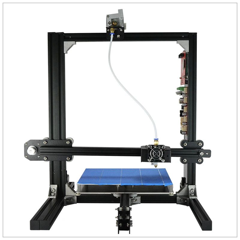 Printer descriptions often indicate a minimum layer thickness parameter. However, this characterizes the print resolution only along one axis ... For the other two, to a large extent, the diameter of the nozzle (the width of the line, which is obtained from the diameter of the nozzle and the thickness of the layer), is decisive. To illustrate, I tried to draw small details in figure 2 with thick lines. At the same time, it should be taken into account that changing the movement of the nozzle at a right angle is an undesirable thing due to the fact that plastic will be applied to some areas twice. This will cause bulging and puckering at the edges, which will degrade print quality. Therefore, more often the corners are printed with certain fillets.
Fig.2
We can see the rounded corners in the picture. Non-continuous filling inside has little effect on strength. In general, a 40-60% part fill rate is usually used, but this depends on many factors. When printing with dry polyamide, I used 15-20% infill.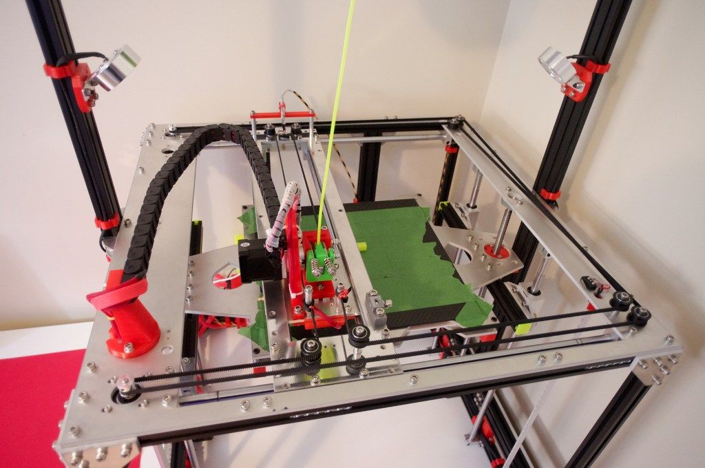 In this case, only the outer contour, the top and bottom of the part are printed in a continuous layer. By default - 3 layers from the edge, then filling. So - for a high resolution of the printed object, a possibly smaller nozzle diameter will be needed. This raises another problem - the speed of printing. Let's assume that our die gives a decent extrusion speed of 100 mm/s, with a nozzle diameter of 0.3 mm. This refers to the speed of extrusion of plastic at the nozzle exit. Let's calculate how much it will be in cubic centimeters, leading to centimeters:
V = L*3.14*D²/4 = 10*3.14*0.03²/4=0.007068 cm³/s 0.007068/0.4 = 0.01767 cm³/s
It turns out that 1 cubic centimeter of a part with a fill degree of 0.4, a printer with a 0.3 mm nozzle will print 56.5 seconds. Roughly 1 minute. A liter part is 1000 minutes, roughly speaking 16 hours. The result is not inspiring. It is clear that if the diameter is doubled, at the same extrusion speed, the printing speed will increase fourfold.
So - if we have the ideal mechanics of the printer, to achieve the best results, we must have the maximum extrusion speed for the thinnest possible nozzle. In the case of a nozzle with a diameter of 0.3 mm, the real minimum radius of rounding of the edges can be from half a millimeter, in my opinion. This is due to some expansion of the fishing line when crushed by the head. Even to a small extent - but it is necessary so that the strength does not fall too much. Many noted the uneven strength of products along the X, Y and Z axes. Along the Z axis, the strength is lower due to the fact that the layers may not stick together strongly enough. With good crushing of the line, for example, the layer height is ½ of the nozzle diameter, this problem is hardly noticeable.
Another goal related to these two is to reduce the mass of the print head assembly. In most printers, the head moves in one or two planes. The faster it moves, the faster printing occurs. There are, however, models where the entire desktop moves.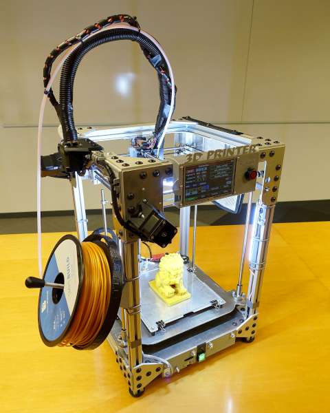 An amazing thing. The work table is much heavier than the head, even with an extruder. In addition, a printed part is stuck to it. Constant sign-variable accelerations must adamantly strive to break it off. And the head is iron, it is difficult to break it off.
Now the head itself is HotEnd. In general, it is not too heavy, but there is one thing - the most common connection option - Greg's or Wade's, implies the placement of an extruder - a node that pushes the filament into the HotEnd, constructively along with the head. This dramatically increases the mass. A bowden connection option, when the extruder is fixed and connected to the head with a long movable Teflon tube (Teflon gives little friction) through which the filament enters the head. This solution is not very reliable, the transmitted force is not so great, and it is also difficult to quickly control the flow of plastic into the head. Not suitable for very high print speeds, in my opinion.
On the other hand, the large mass of the movable head with the extruder, during rapid movement, causes heavy loads on the printer frame, while additional energy is required to move all this mass. This means that one of the considerations should be to reduce the overall weight of the print assembly.
Pins:
Three main tasks affecting the speed and quality of printing:
1. Obtaining a workable nozzle with the smallest possible diameter
2. With high speed
3. And at the same time, so that the mass of the printing unit is as small as possible.
These are issues, the solution of which, I believe, is important for the improvement of FDM 3D printers and the ways to solve them will be discussed here.
Chapter 1. Head, general device and processes running in it. Extrusion. Friction.
1.1 Head zones. In order to solve the listed tasks, it is necessary to understand the processes that occur in the head in order to optimize them. So, let's take a simplified diagram of the inside of the head. see fig.3
Fig.3
Let's see what processes take place in the designated areas.
In zone A , we see the incoming cold filament. Its properties have not yet changed from heating, so its resistance to movement is determined by friction against the walls. It can be well reduced by using a Teflon liner - a tube, since Teflon works well at not too high temperatures, in conditions where it has nowhere to flow (just a liner), and the sliding friction on it is very low.
Plot B is now green. In this part, the plastic is already somewhat heated from the walls and its mechanical properties are deteriorating, but fluidity is not yet manifested.
I suspected the existence of this section from the results of experiments with a very long melting chamber with a narrow channel (for better thermal contact).
Unexpectedly, the extrusion speed dropped a lot. In this case, the gap in diameter was about 0.1 mm. I assumed that with partial heating, the strength of the plastic rod drops, and it begins to bend in the channel under the pressure of an extruder with a smaller bend radius, that is, there are too many friction points against the wall, or even a slight swelling causes a plug to form, but not where it is necessary, not in the zone of high temperature gradient (More on that below).
In favor of the formation of such a snake-spring is evidenced by the fact that a large post-extrusion was observed during extrusion. That is, after the extruder stops, plastic continues to choke from the nozzle. To check and fix, the channel was reamed to 2.0mm from 1.8mm. The gap was 0.3 mm. The speed has increased significantly. This phenomenon is probably more typical for a filament of small diameter, since the bending stiffness of the rod decreases with decreasing diameter according to the law of either the third or the fourth degree. However, with absolute certainty, this cannot be considered the main reason for the failure in this case, since another error was eliminated - too long outlet section of the nozzle. 4-5 times longer than recommended and usual. Due to a manufacturing error. However, judging by the calculations of the friction forces in the nozzle nose (given below), the long exhaust channel should not have given such a speed reduction.
Section C. The temperature rises and plastic deformation of the bar begins. Under pressure, it is distributed to the sides, forming a piston. I found a description of this phenomenon on the page http://reprapology.info/archive/1422/rheology/ Thank you, colleagues! This moment was quite easy to check - on a line diameter of 3 mm, it was enough to let the head cool after printing, and then, using rapid heating, remove the line with a hardened influx. The design of the head allowed me to do this easily.
So, the resulting piston serves as an obstacle to the hotter liquid lower layers of plastic and prevents them from breaking through to the top. Such breakthroughs happened under certain conditions, I could also observe them. Therefore, this phenomenon is useful, which is why I call it "work jam". However, under a number of conditions, the cork begins to grow in length. A tight fit to the walls over a large area of the semi-solid mass dramatically increases the resistance. There is a "plug" - congestion. I was also able to get this phenomenon on my experimental heads, although under certain conditions.
The fact is that, of course, mainly the plug occurs due to the unsuccessful design of the head and only as a result of this, more often during downtime in a heated state. Obviously, and it is clear from the figure that the section of the “working plug” must have a certain length - no shorter, and no longer than the optimal one. I did not manage to meet the “working plug too short” defect, but “too long” is a common occurrence. It is clear that if we consider the stationary state, the length of the “working plug” is determined by the temperature difference (gradient) from the beginning of zone C to its end. In the case of plastics with a working temperature of 230C, the lower temperature of the beginning of its formation is probably in the region above 100-110 C. Actually, this fact explains the use of fans and thermal barriers in working heads - when printing is stopped (and not only), they prevent the rise heat up, and, accordingly, the growth of the cork and its displacement into undesirable areas.
Plot D. Not an easy one either. The fact is that in this zone the plastic must be melted to the very center, that is, completely. Otherwise, if an unmelted core approaches the nozzle, there is an uneven extrusion of plastic - it is not a continuous fishing line that is choking, but a kind of garland of sausages with constrictions, or for pessimists - "poop". At slightly lower speeds, using freshly dried polyamide, one can see in the extruded transparent fishing line, along the axis, small inclusions of unmelted cloudy plastic of a cylindrical shape. Such a phenomenon was well observed on a type 3.3 head with a filament diameter of 1.6–1.7 mm and a nozzle diameter of 1 mm, at a filament feed rate of 500–1000 mm/min. Here are some photos.
An example of non-dried polyamide at a feed rate of 500 mm/min, a temperature of 225°C, line slippage in the extruder is about 10%.
Fig.4
It can be seen that the line is almost everywhere even, only strongly bubbly. Don't be alarmed - this feature is the result of a combination of a huge exit nozzle diameter and a high feed rate.
Everything is the same, but the filament feed rate is 1000 mm/min, and the slip coefficient is about 50%! That is, in reality, the supply increased by hardly 5-10%. Slip coefficient I use to denote the fact that with an increase in the feed rate, the speed of extrusion of the line increases and, accordingly, the resistance to pushing the line increases. At some point, the teeth of the hobbolt can not cope with the capture of the fishing line, and begin to tear through it, or slip along it. In this case, the set feed rate begins to exceed the actual one - we determine it by the weight of the extruded fishing line. For 100%, I consider the complete compliance of the innings, for 0%, the complete cessation of the innings. This value characterizes the extrusion pressure very well, 80% usually means a stable and uniform process.
Fig.5
A certain lumpiness is visible, although it is poorly visible due to blistering.
Fig.6
Here is dried polyamide, filament diameter 1.7mm, feed rate 500mm/min, temperature 215ºC. There is no blistering, there are constrictions. By the way, drying was carried out in an electric oven, 30 minutes at 100ºС, 30 minutes at 120ºС. Shrinkage 5.5% of the mass. Further drying for an hour at 120ºС led to a decrease in weight by 0.5-1.0%. At the same time, my fishing line was partially deformed - probably the oven is not the best device for drying.
Conclusion - 1 hour, with a stepwise rise in temperature, it is enough for drying. The extrusion rate was not significantly affected by drying. Important point! Over time, both polyamide and ABS absorb moisture from the air. When printing, this leads to the appearance of bubbles in the line, which means protrusions and bumps on the finished product. This has to be fought.
Fig.7
A good, uniform fishing line, diameter walks a little. Feed 300mm/min. Slippage is almost zero.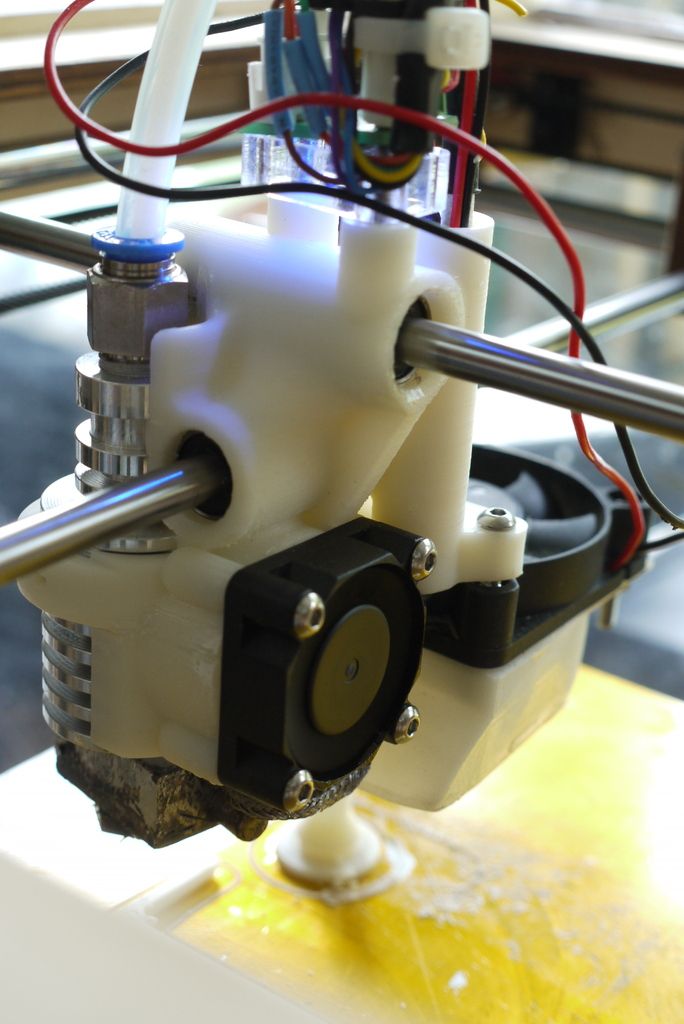
Section E - flow compression zone. Theory teaches that the shape and length of this section is not too important - the shorter the better. There were suspicions, some comrades from the Roboforum, that due to the viscous-elastic nature of the polymer melt, this might not be the case. Experiments have confirmed the advantage of the simplest nozzles, with a large entry angle, obtained by drilling with a conventional drill, in one pass. All sorts of stepped drilling, elongated conical nozzles (up to an elongation of 1k13), nozzles with a parabolic profile were tested, and turned out to be much worse in friction than the simplest nozzle made using a drill with a sharpening angle of 118º. So, at the moment, I think it doesn't make sense. A question with a filled filament - this may not be the case.
Area F - nozzle nose. In practice, the shorter the better. Recommended up to 0.4 mm. This is the section with the most resistance, so its length greatly affects the resistance. With a length of 0.4 mm and a nozzle diameter of 0.2 mm, as it turned out, 49% of the total resistance falls on this section. This is for the latest version of the V4_1 head. The method for obtaining this data will be discussed below. But it must be taken into account that the lengthening of this section leads not only to a decrease in speed, but also has a smoothing effect on the stream, reducing swelling at high speeds. True, this still needs to be clarified whether this affects the quality of the print - after all, anyway, the stream is immediately smeared over the part
Conclusions: The division of the head according to the processes running in it into zones is described. The main processes in them going. Working plug-piston. Friction. Complete melting of the filament. Water content in the filament, its effect, drying. Alternative nozzle shapes are step drilling.
1.2 Calculation of the filament melting rate and its influence.
Melting rate of cylindrical plastic bar with surface counted
according to the Fourier law, assuming that heat is not spent on a phase transition (like ice melting), (which is not very true in the case of polyamide - it has a noticeable crystallinity, but the error is small), that there is no mixing of the molten layers - this is close to the truth, because, due to the high viscosity of the molten plastic, its flow in a pipe of not too large diameter (1. 7 and 3.0 mm) is laminar.
I calculated for a thin cylindrical layer of plastic, the thermal power entering this layer: P = λ * S * ΔTdv / l, where λ is the thermal conductivity of the plastic, S is the heat transfer area, l is the thickness of the thermal conductivity layer, counting from the heated surface. ΔTdv is the driving force of the process, the temperature difference between the heating and heated surfaces. In the event that the power exceeded the heater power, ΔTdv was substituted into the formula, calculated from the condition of equality of the heater power. According to the formula Q = M*C*Δtr, we calculated ΔTr, the change in the temperature of the heated material on a given layer, at a given time step. Thus, it was calculated in layers, with a fairly small step in the Calc table from the Libre Office package. I took a step size of 0.15 mm and a time interval of 0.02 s.
Now let's see how the object will be heated from a heating surface with a constant temperature - as in our case. From the Fourier law we know that the heating rate is proportional to the temperature difference - i.e. - "driving force", Δt. Let's count. Heating surface t=250 ºС, target temperature t=230 ºС. Initial temperature t=20 ºС. Let us take the time during which heating occurs by a third of the initial temperature difference ((250-20) / 3 \u003d 77 ºС) equal to T. In this case, the final temperature on the interval t \u003d 97 ºС (20+77), and the average Δt = ((250-20)+(250-97))/2=191 ºС. During the next time interval T = 2, the object will also heat up by a third of the remaining “driving force” Δt = 250-97= 153 ºС, and the final temperature on the interval will become t=97+51=148 ºС and the average Δt = ((250-97) + (250-148)) / 2 \u003d 127.5 ºС.
For the time interval Т =3, Δt = 250-148= 102 ºС, and the final temperature will become t=148+(102/3)=182 ºС and the average Δt = ((250-148)+(250-182) )/2=85 ºС.
For T =4, Δt = 250-182= 68 ºС, the temperature will become t=182+(68/3)=205 ºС and the average Δt = ((250-182)+(250-205))/2= 56. 5 ºС.
5 ºС.
For T =5, Δt = 250-205= 45 ºС, the temperature will become t=205+(45/3)=220 ºС and the average Δt = ((250-205)+(250-220))/2= 37.5 ºС.
For T = 6, Δt = 250-220= 30 ºС, the temperature will become t=220+(30/3)=230 ºС and the average Δt = ((250-220)+(250-230))/2= 25 ºС. So, when heated from the surface with a slight overheating (20ºС), it turned out that the set parameters were reached in 6 conditional time intervals T.
Now let's see what happens if we increase this temperature difference. Let's calculate the same heating from the heating surface with t = 320 ºС - such a technical possibility is available in the head of this design.
Т=1, Δt = 320-20= 300 ºС, the temperature will become t=20+(300/3)=120 ºС and the average Δt = ((320-20)+(320-120))/2=250 ºС.
Т=2, Δt = 320-120= 200 ºС, the temperature will become t=120+(200/3)=187 ºС and the average Δt = ((320-120)+(320-187))/2=166 .5 ºС.
Т=3, Δt = 320-187= 133 ºС, the temperature will become t=187+(133/3)=231 ºС and the average Δt = ((320-187)+(320-231))/2=111 ºС.
It turns out that by heating the plastic with a hotter than necessary head, we will noticeably increase the melting rate. Not bad, this solution can come in handy, although there will be a number of complications. In addition, this will have a positive effect on the viscosity of liquid plastic, because the rate of plastic melting is not the only factor limiting the rate of plastic outflow from the nozzle. This was taken into account in the calculation, thanks to which it became possible to consider the operating mode with overheating. It turned out a wonderful table made in LibreOfficeCalc, which allows you to calculate the heating of the bar with a set of factors and makes it possible to calculate where and what the temperature will be. Do not scold for using an analogue of Excel - it does its job.
The total melting time of polyamide PA6 with a diameter of 1.7 mm, at a heater temperature of 280ºС, up to a temperature of 200ºС, with a heater power of 30 W, turned out to be 2. 88 s, and in the case of a heater with a temperature of 240ºС - 3.24 s. For the same plastic with a diameter of 3 mm and a heater power of 50 W, with a heater temperature of 280ºС and heating up to 200ºС - 8.64 s, and with a heater with a temperature of 240ºС - 9.84 s. This is the calculation data when substituting the parameters of real heads type 4.1 and 3.3. Also, according to the calculation results, the profile of the filament melting front in the head was built.
Fig.8
From the value of the time required for the melting of the rod, one can calculate the required length of the melting zone or the maximum possible melting rate of the filament.
For experimental verification of calculations for a 1.7 mm filament, I used a type 3.3 head with a nozzle drilled to 1 mm for 1.7 mm filament, and a type 4.1 head with a 0.9 nozzle for 3 mm filament. Such a large orifice should have greatly reduced the resistance to bursting due to viscosity, leaving only a limit to the bursting of the unmelted mass. Since the melt flow rate from the nozzle is much higher than the filament advance rate (proportional to the difference in the squares of the diameters), the unmelted part of the filament cannot just go into the hole, it blocks the nozzle, and if it is smaller than the nozzle diameter, then it is torn into pieces by the flow . The temperature is already quite high, so the strength of the unmelted core is low. This phenomenon can be observed during the extrusion of dried polyamide (undried melt is turbid due to vapor bubbles), in the molten state it is transparent, and in the hot solidifying fishing line from the nozzle, small cloudy islands of inclusions were visible along the axis.
How output, and therefore slippage, was measured: First, the extruder was calibrated. On assignment (for example) 50 cm, he pressed the fishing line at low speed to be sure that there was no slippage. It was measured how much he really pushed through. Marks were made on the line with a felt-tip pen. The specific gravity of the filament was calculated - a piece of filament 1 m long was cut off, the diameter was carefully measured in several places. This piece was weighed. Density was calculated from these data. - By the way, the type of polyamide can be judged quite well by density, and this allows us to judge its other characteristics, such as strength, melting point, water absorption.
The maximum actual feed rate of the filament when heated to 280ºС for a diameter of 3 mm was 6.52 mm/s. For this head, the length of the melting zone can be considered to be about 50mm. So, the melting time from the experiment is τ = 50/6.52 = 7.67 s. This is the time of complete melting of the filament with a diameter of 3 mm. To be more precise, it was not a filament, but a trim line, its diameter was stable. In the case of a trimmer line with a diameter of 1.6mm, its diameter "walked" from 1.62mm to 1.68mm. For such a filament, the rate of complete melting was 4.17 s. The difference from the calculated one is somewhat larger than in the first case. I understand that this is due to the resistance of a narrower working channel .. Quite a good match with theory. The rate of complete melting for a different diameter is likely to be quadratic (and calculated for a 3 mm filament, this confirms).
Conclusions: Mathematical calculation of the time of complete melting of filaments of different diameters for different head parameters and heating conditions, for different types of plastic has been performed. Its value for the final extrusion speed is shown. The quality of the model was experimentally verified. The possibility of a significant improvement in the rate of complete melting of the filament has been proven. Increasing the temperature of the head increases the melting rate of the plastic.
1.3 Influence of friction. His assessment. Thermal barrier. Hot radiator. It appears in all parts of the head. Friction of cold plastic, friction of slightly heated plastic due to swelling to the sides, friction of the “working plug”, friction of liquid plastic against the walls and between layers, and unexpectedly high resistance in the last section of the nozzle. Although it is usually recommended to make it short, but due to the fact that the speed of the plastic in this place is the highest, and the diameter of the hole is small, the resistance can be very significant.
Friction up to the die and in the extruder is also important, but now we are dealing with the die. Using a Teflon liner inside the head seems to be a bad solution due to the high temperature, however, due to the melting of the plastic, friction is reduced here, which means that the need for Teflon disappears. However, dry friction on metal must be avoided, and while plastic glides fairly well on polished steel, aluminum does not.
So, returning to the drawing of the head with zones, picture 3 is zone C, the zone of formation of a working plug.
To reduce friction in this area, it is necessary to create a large temperature difference (gradient) from zone C - the formation of a working plug, to zone D - melting. The greater the gradient, the shorter the length of the working plug and the lower the friction resistance. A thermal barrier is used to create an appropriate gradient. Starting with the first type 1.1 heads, I made it using a stainless steel tube soldered (with silver hard solder) to a brass head, a small aluminum disk radiator was put on the tube, at a distance of about 2-4 mm from the brass part of the head. Due to the low thermal conductivity of stainless steel (grade 304, or X18H10) and the high thermal conductivity of aluminum, the radiator acquired a temperature of about 100ºС, and preheated the fishing line, reducing the melting time, without the risk of plugs. Since the radiator was blown by a fan, good thermal stabilization was obtained - the cork could not rise up, because with an increase in temperature, the radiator began to give off heat much more intensively. On the section of the steel tube at the level of the radiator and above, a Teflon liner was used from the inside, thus the increased friction of section B was reduced.
1.4. Traffic jams. Consider, if possible, the process of formation of traffic jams in the head and their transformation from useful "workers" into harmful ones. To do this, we calculate the heat fluxes in different parts of the head and think about it.
In general, during the operation of the extruder and die, the plastic line is converted into a melt and pushed with a sufficiently large force through a narrow nozzle opening. This is clear. By the way, according to some considerations, it can be estimated that the melt in the head can be under sufficiently high pressure. The force of a good extruder can reach tens of kilogram-force per 3mm filament. I applied this kind of force to the bar when I pressed through the plastic manually. It happened. It reaches an area of 7 square millimeters under 100 atmospheres. Well, this is not too difficult to measure - we insert a rod made of a material with low thermal conductivity (PEEK, PTFE?) into the nozzle and measure the flow plugging pressure. For a nozzle with a diameter of 0.5 mm - 2 grams-force per atmosphere. Although it's not too important. I did not measure.
So, the fishing line enters the head with a gap. Nothing breaks back. It is clear that when heated, some softening of the plastic occurs and, under the action of the force of the extruder, it is distributed to the sides, as long as the walls allow. The property of plastic to partially soften is easy to check - this is true.
Again, it is clear that the smaller the temperature difference along the length of the plug, the more extended the plug will be. The greater the length of full contact of the plug with the walls, the greater the resistance to pushing through. You can see picture 3 ... Further, when the plastic melts, the friction against the walls becomes less and you don’t have to worry about it so much. So, the shorter the working plug, the less parasitic friction.
Let's imagine that the working plug is only 0.1 mm long. It is clear that such a thin layer of a generally not very strong material will not withstand the return pressure of liquid plastic, and it will break back, and having broken through, it will freeze in the cold part, creating an unexpected traffic jam. I've had to pull these out a couple of times. There you can clearly see how a breakthrough occurred and the liquid rose up along the whole filament rod. By the way - in ALL cases when I had traffic jams (although I had a lot of experimental heads, but traffic jams rarely formed), I got rid of them very simply - I let them cool, then turned on the heat, after a few minutes the “Reverse” command on the extruder and hand with pulled out by force by the fishing line. My guess is that this may be due to the design feature of all my heads. - Before the zone of active melting, inside the tube there is a Teflon liner, with a diameter not less than the diameter of the working zone of the head.
Conclusion: Plug growth and sticking occurs, I believe, due to the fact that, when idle, heat rises up the walls of the head holder (thermal barrier?), And when work begins, soft plastic is distributed to the sides. It probably becomes fatal when there is no Teflon liner that reaches almost to the very head.
1.5 Calculation of heat flows and gradients at rest and in motion, in the head. Hot radiator calculation with and without it.
1.5.1. Head design BASS type 1.3 and heat flows in it. Name according to the first letters of the used materials Brass, StainlessSteel, Aluminum. For 3mm filament. Consider heat flows, temperatures and processes using this design as an example.
Inserting a piece from my old publication
"Zd-printer: a view from the side of the head", slightly corrected.
Fig.9
9: purple on the outside of the head is a heating coil, preferably made of nichrome, however, a resistor is often used as a heater in heads - this is convenient in production, but reduces the reliability and uniformity of the heating field, since the resistor is located locally, therefore it experiences local overheating. However, there is no fundamental difference here - a resistor or winding. Only - high uniformity and heating rate, and lightness and accuracy of the design.
The red area at the bottom of the head is the zone of molten polymer, it is not uniform, since the polymer changes viscosity over a wide temperature range, and the orange zone is the area where the polymer has already warmed up to plasticity, but is not yet fluid. This zone is very important - in it the plastic rod expands slightly, fits snugly against the walls and turns into a piston, which pushes the melt through the outlet - the die. Green - a zone where significant changes in plasticity have not yet occurred and the bar transfers pressure further without crushing. Different shading depicts a brass head and an aluminum heatsink. The fluoroplastic tube is highlighted in white - the guide, due to very little friction, the bar passes through it with minimal resistance. Gray - stainless steel tube that carries the head and radiator, as well as a ring - liner - it avoids mechanical stress on the Teflon tube in the hottest part. This is important - Teflon, under such conditions, is extremely mechanically fragile, so here it rests everywhere on steel - it can leak a little, but not soon, and this piece of Teflon tube is very easy to replace. The stainless steel tube is soldered to the brass head with hard silver solder, so there are no questions about thermal stability and strength. The ring (polished from the inside to reduce friction!), is simply inserted inside and pressed down with a Teflon tube from above. Please note - stainless steel should be with low thermal conductivity, for which it was chosen. Usually it's something like 04X18H10.
On the left side of the picture, you can see the temperature plot (approximate graph), along the axis of the tube. I can't vouch for the accuracy of the scale, but the directions are correct. The farther from the axis with zone markings, the higher the temperature.
Let's not repeat ourselves. Only zone 4 is interesting here. You can see how the hot radiator is placed.
Zone 4 - zone of active plastic softening, thermal barrier zone. It can be seen that there is a small gap between the brass part of the head and the radiator, where the temperature changes very sharply.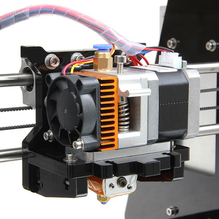 Here the plastic begins to heat up to form a cork, which serves as a piston pushing further and further. As colleagues from reprapology.info have shown, if the piston plug increases in length, this leads to printing stops due to increased friction and excruciating cleaning problems. To prevent this plug from growing, a small radiator is used above, in the 5th zone. With the influx of heat through the stainless steel thermal bridge, it heats up, which means it begins to dissipate more heat. Thus, the process self-stabilizes and it becomes not at all difficult to get into the area of stable operation. The heat dissipation of the heatsink is high, and the thermal resistance of the bridge between the head and the heatsink is large, so the rise in temperature with distance is high, which means that the point of optimum operating temperature is likely to fit in this segment for creating a short, efficient piston. The size of the hot heatsink must be chosen so that its temperature is in the region of 100-110 degrees, probably (this is the usual temperature of the printer's desktop).
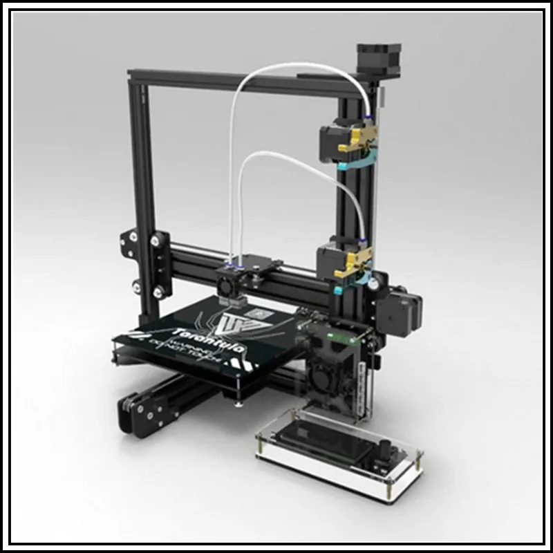 This is done so that as much of the thermal barrier zone as possible is within the likely operating temperature range (plugging!).
So, in short, for stable operation of the head, the existence of a narrow zone with high thermal resistance (it is called a thermal barrier) is necessary, in which the temperature would change over a short distance from the operating temperature (we consider 235) to 100 degrees - approximately the operating temperature table. You need continuous airflow with a small fan and it should be directed precisely at the radiator!
Conclusion: The principle of design and operation of the head with the use of a "hot radiator" is described.
1.5.2 Calculation of the heat flow from the head. Calculation of the heat flow in the area from the head to the hot radiator. - thermal conductivity of stainless steel (grades 304/316) K = 9.4 W / C ° * m
Head dimensions: thermal barrier length from the head to the hot radiator L=3mm outer diameter D=8mm , inner diameter - due to the insert-ring d = 4mm
- Consider the temperature of the head 260°C.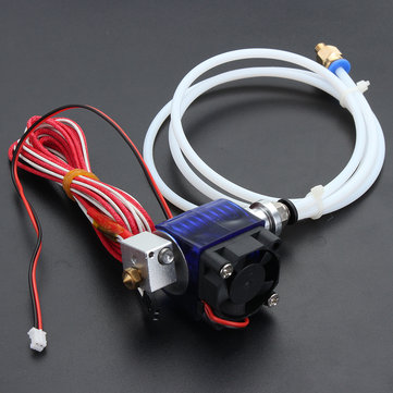
- We consider the normal working and desirable temperature of the hot radiator T = 110 ° C
- Convective flows in the case of a 3D printer head, which is blown by a fan and constantly moving fast enough, can be ignored. Cooling by moving air of the radiator and other parts will not be taken into account separately; to calculate the power dissipation, we use an approximate formula for radiators, considering a moving and slightly blown head similar to a radiator under normal conditions. Heating from the surface of the heated table is also neglected due to, on the one hand, a sufficiently large distance from its surface and, on the other hand, blowing and moving the head. We believe that to some extent they are mutually compensated. However, on a working printer, the parts above the heated table do not noticeably heat up.
- Up to a temperature of 100 ° C, it is not recommended to consider heat transfer by radiation at all - it is too small, with increasing temperature it grows in proportion to the fourth power of temperature. Cooling the head with radiation - we care very little, there is a temperature sensor there, if it cools down, we will heat it up. The temperature of the hot radiator is close to the recommended 100°C for non-calculation - radiation is not counted.
The section of heat conduction transfer from the head to the hot radiator.
Transfer area S= 3.14*D²/4 - 3.14*d²/4 = 3.14*8*8/4 - 3.14*4*4/4 = 37.7 mm²
To convert it to square meters, in the case of the coefficient of thermal conductivity given to us, the area must be divided by one million.
Let's calculate the heat flow to the hot radiator. Due to the fact that the thermal conductivity of aluminum is 50 times higher than that of stainless steel, we consider the temperature to be uniform throughout the radiator (along the axis is 5 millimeters). The temperature at the edges of the radiator is not of interest to us in this calculation.
W= K*S*ΔT/L
L - do not forget to divide by 1000, because the coefficient we use uses the unit - meters, in the area from the head to the hot radiator ΔT = 260 -110 = 150 ° С
It turns out W = 9.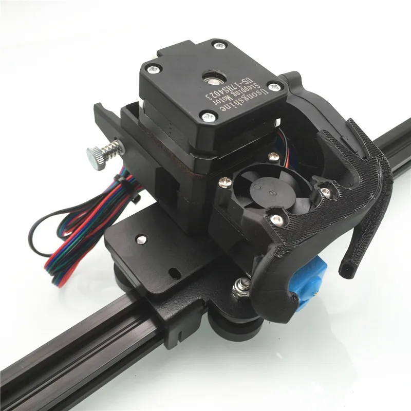 4 * 37.7 * 150 / 3 * 1000 - a million (area in mm²) and a thousand decreased, a thousand remained.
W= 17.72 W of heat flow into the hot heatsink.
1.5.3. Calculation of the heat balance of the radiator. Gradient calculation. Calculation of the heat flow in the area from the hot radiator to the head mounting:
- Thermal barrier length L=8 mm
- Transfer area S= 3.14*D²/4 - 3.14*d²/4 = 3.14*8*8/4 - 3.14* 6*6/4 = 21.99 mm²
there is no liner ring in this area, so the inner diameter has increased, and the heat transfer area has decreased
- Temperature difference. We consider the normal and expected head mounting temperature to be 30°C, which means ΔT = 110-30=80°C
We consider W= 9.4 * 21.99 * 80/8000 = 2.07 W
- 17.72 W of heat enters the radiator , and 2.07W comes out, the difference Δ W = 15.65W
The radiator must dissipate this heat into the air. In operation, part of the heat will be carried away by the filament, which is heated in this area from the walls of the tube. However, we will not consider this yet. It turns out that we need to assume that all this heat is dissipated by the radiator.
Calculation of the heat flux dissipated by a radiator using a simplified formula.
- Q=50/√S Where Q is the thermal resistance of the heatsink, in degrees per watt, and S is the area of the heatsink, now in square centimeters... that's the formula. Yes, the formula is weak and lies at times, but according to the measurement data, it is possible to introduce an amendment for specific conditions. We take into account. This radiator has an outer diameter of 20 mm, an inner diameter of 8 mm. Height - 5 mm.
- Let's calculate its working area, it consists of the upper disc, lower disc and radiator fin area. S= 2*(3.14*D²/4 - 3.14*d²/4)+3.14*D*H = 2*(3.14*20*20/4 - 3.14*8*8/4)+
3.14 * 20 * 5 = 841mm² = 8.41 cm²
- Calculate the thermal resistance of the radiator Q = 50 / √8.41 = 17.24 degrees / watt
- Calculate the temperature at which such a radiator can dissipate 15.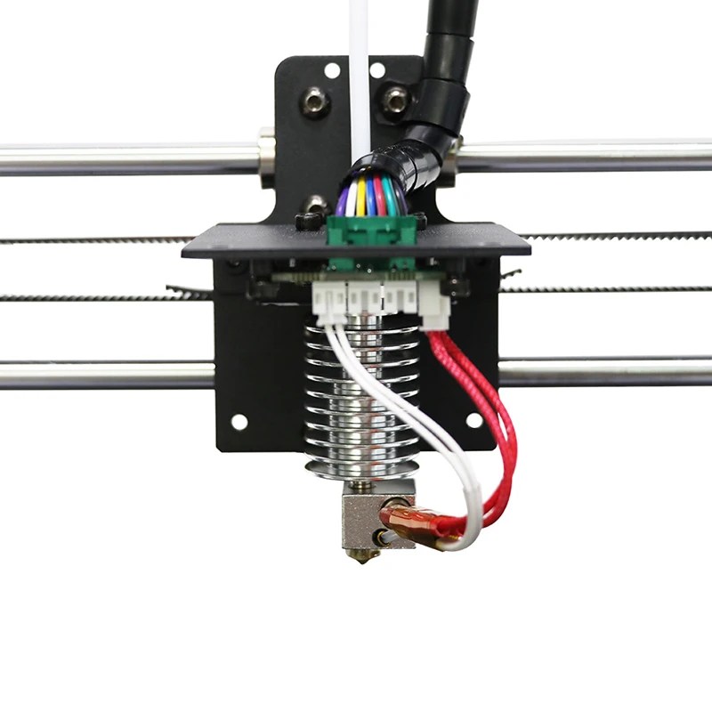 65 W of heat received at the end of the second paragraph of the calculation. ΔT \u003d 15.65 * 17.24 \u003d 270 ° C And this is the temperature difference. We consider the air temperature in a working printer to be 30 ° C, an absurd temperature of 300 ° C will be obtained.
Now it would be nice to check the calculations.
With heated table turned on at 110°C and head at 260°C
electronic thermometer inserted into the hole for the screw on the radiator measured the temperature to the maximum readings within a few minutes.
The temperature turned out to be much lower than the calculated one - 111.9°C instead of 300°C
This clearly signals the inaccuracy of the model. The weakest link here is the formula for calculating the thermal resistance of a radiator, it is empirical and calculated for a radiator without forced cooling. In our case, there is a fan, although it is weak and blows from afar. I consider it possible to introduce a linear ventilation coefficient to clarify the calculation of thermal resistance.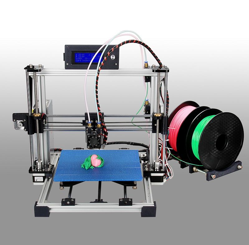 Let's calculate it by substituting into our formulas in the form of
Q=50/(√S*K). initial temperature 260°C. Let's take the temperature of the hot radiator 111.9°С
W= K*S*ΔT/L In the area from the head to the hot radiator ΔT = 260 -111.9= 148.1°С
It turns out W \u003d 9.4 * 37.7 * 148.1 / 3 * 1000 \u003d 17.49 W.
Calculation of the heat flow in the area from the hot radiator to the head mounting:
- Transfer area S = 3.14*D²/4 - 3.14*d²/4 = 3.14*8*8/4 - 3.14*6*6/4 = 21.99 mm²
— Driving temperature difference. Head fixing temperature 30°C, so ΔT = 111.9-30 \u003d 81.9 ° С We consider W \u003d 9.4 * 21.99 * 81.9 / 8000 \u003d 2.11 W
- It turns out that 17.49 W of heat enters the radiator, and 2.11 W comes out, the difference ΔW = 15.37
Calculate the thermal resistance of the radiator. Let's take K = 3. That is, the efficiency of our radiator increases three times due to the fan blowing. Q=50/√8.41*3 = 5.75 degrees/watt
Calculate the temperature at which such a radiator can dissipate 15.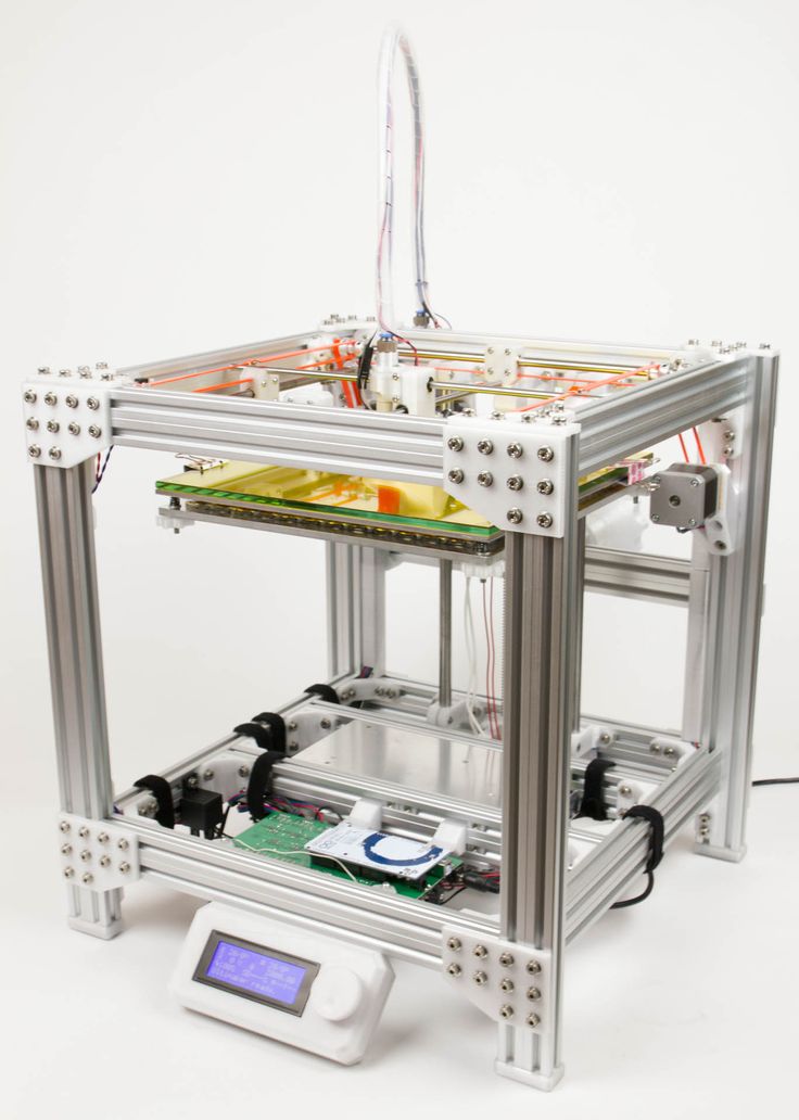 37 W of heat
If the air temperature in the operating printer is 30°C, the temperature will be 118.37°C.
If we calculate the heatsink temperature with the obtained coefficient for a head temperature of 220°C = 94°C and compare it with the measured 97.7°C, we get a good match.
Conclusion: Temperature gradient for the case of 260°С G=(260 - 112)/3=49 °С/mm. We can read the temperature of the "hot heatsink" with good accuracy and the heat flow into the head mount. Accordingly, we can set the required ones by changing the corresponding dimensions.
1.5.4. Calculation of heat flow from a head without a hot heatsink and comparison of gradients.
How will things be if we don't install a radiator? Let's count. We will count the flows without an insert ring, it was conceived for the temperature unloading of a Teflon tube and makes sense only in conjunction with a hot radiator. For a temperature of 260 ° C, the heat flow into the mount in the case of a radiator will be 2.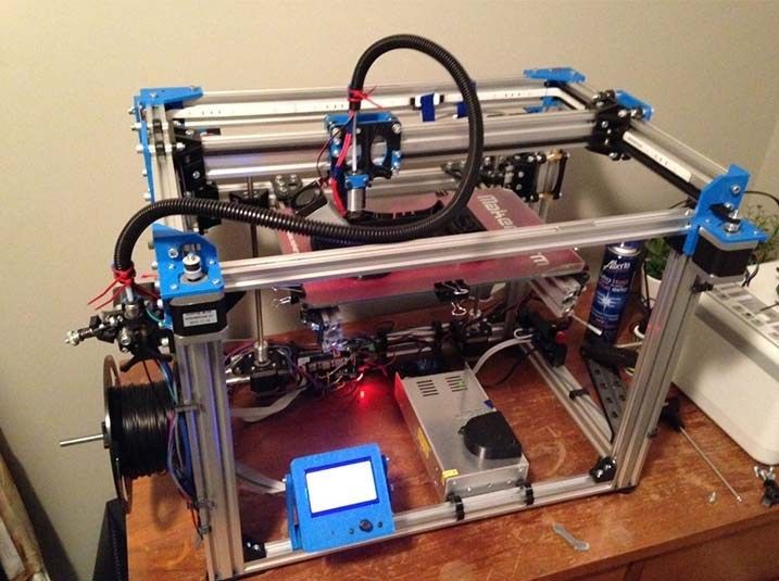 07 W watts.
Calculation of the heat flow in the area from the head to the mount:
— Length of the thermal barrier L=8+3+5 =16 mm We add up all the lengths — and the radiator too.
- Transfer area S= 3.14*D²/4 - 3.14*d²/4 = 3.14*8*8/4 - 3.14*6*6/4 = 21.99 mm²
- Temperature difference. We consider the normal and expected head mounting temperature to be 30°С, which means ΔT = 260-30=230°С
We consider W= 9.4*21.99*230/16000 = 2.97 W However, one and a half times more.
Let's calculate the gradients for 16 mm G = (260-30)/16 = 14.4 degrees/mm.
A big difference from 49 degrees/mm, especially considering that in the case of a radiator, when idle, the plug will rise by more than half of the entire area, that is, at a distance of 8mm of the thermal barrier, the temperature will be ΔT/2 + T = 230/2 +30= 145°С This temperature is unequivocally above the beginning of cork formation and below melting. Moreover, this length of the cork 8-10 mm is enough to stop. And in the case of a fan, more than 3 millimeters of plugs during idle time will not work.
Conclusions: a "hot radiator" actually prevents the risk of plug formation when using a Teflon liner and increases the operating temperature gradient, which leads to a decrease in friction in the working plug area.
1.5.5. Calculation of heat fluxes in the head with uniform movement of the filament.
Same conditions, same head. The filament flow moves at a speed of 1.5 mm/s, which corresponds to the extrusion speed for a 0.3 mm nozzle = 150 mm/s or for a 0.5 mm nozzle = 54 mm/s. The density of polyamide is 1.18mg/mm³. Since the significantly hot section (100-110C) to the head has a length L = 5 mm (the length of a hot radiator), at a speed of 1.5 mm / s, the filament passes in 3.3 seconds, while the walls are closed with a Teflon liner with a thickness l = 1mm=0.001m and inner diameter D=4mm, we can calculate the possible heat flow given off by the walls:
P= λ*S* ΔT/l, where λ=0.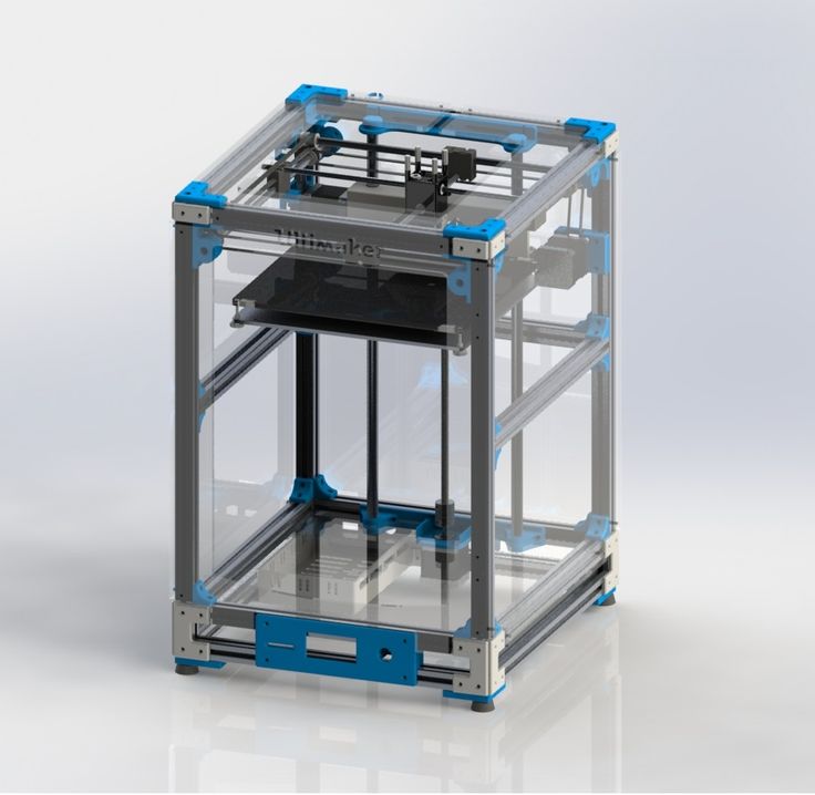 25W/m*K is the thermal conductivity of Teflon, S= π*D*L=3.14*4*5=62.8 mm²=0.0000628m² is the heat transfer area, l is the thickness of the thermal conductivity layer. ΔT is the temperature difference. The temperature of the hot radiator is about 110°C, the incoming filament will warm up a little, so we consider the temperature at the inlet to be 30°C ΔT=110-30=80°C.
P= λ*S* ΔT/l= 0.25*0.0000628*80/0.001=1.25W, 1 millimeter of filament can receive 1.25/5 = 0.25 joules of heat every second. For 3.3 s, the time spent in the radiator, he will be able to get 3.3 * 0.25 = 0.825 J. Let's calculate the power required to heat 1 mm of incoming plastic at ΔT= 80°C. Volume = 1*3.14*D²/4= 1.5*9*3.14/4=7.065mm³/s
Mass = 7.65*1.15=8.124mg/s
Power, Q = M*C*ΔT= 8.124*1700*80/1000000 = 1.1W This is the case when all plastic is heated from an initial temperature of 30°C from a radiator with a temperature of 110°C.
So, the heat that 1 mm of filament can receive, passing through the radiator, through the Teflon wall, will be = 0. 825 J. For the same time, to fully heat up to 110 ° C, the same slice, 1.1 joules will be required. Using the plate for modeling the warming up of the bar, made for paragraph 1.2, I calculated it more accurately. With a length of a hot radiator of 5 mm, its temperature of 110 ° C, and a speed of movement of a filament with a diameter of 3 mm and a temperature of 30 ° C, with a heat flux into the radiator of 15 watts, the heating of the very middle of the filament will be only 2 degrees, but 1 mm of the rod will be able to accept 0, 88J of heat, which is just over 0.825J that can penetrate. 0.825 J will be about 75% of the total heating. If the length of the radiator is 10 mm, then the bar will receive 1.06 j of heat, which will be 96% of full heating, and the very center will warm up to 32 ° C. For 100% warming up, you would have to bring the length of the radiator up to 30 millimeters, and this does not make much sense - it will melt in the head anyway.
Here are the details for the head type 3. 1, for 1.75 filament. Just for beauty.
Fig. 10 Details for the head Type 3.1
Conclusions: - power required to heat the incoming plastic at a given speed: 4.25W
- heat flow given off by the walls to the filament in the hot radiator area: 2.00W
- The start of plugging at full flow is shifted deeper into the head.
- At high flows, for the effective operation of the "hot radiator" mechanism, it will be necessary to increase the heat flow between the head and the radiator and the length of the contact area with the radiator. Factor of.
- It is possible to use a separate hot radiator fan, controlled by a temperature sensor, so as to keep the temperature around 100ºС.
The use of a hot heat sink is not at all necessary, but it seems to be a simple way to aggravate the temperature difference in the holding tube, avoiding the danger of the working plug growing to the size of a blocking plug and helping to solve the problem of cooling the head mounting.
The second part is coming soon.
How to choose an extruder for a 3D printer
3DPrintStory 3D printing process How to choose an extruder for a 3D printer
Hello friends. Today we will talk about choosing an extruder.
In simple terms, an extruder is a mechanism whose task is to feed molten plastic into the printing zone. It consists of a feeding mechanism and a print head.
Two types of extruders
There are two main types of extruders: bowden (bowden) - in the picture on the left and direct (direct) extruder - in the picture on the right. With a direct extruder, the plastic feed mechanism is located in close proximity to the print head. In bowden - at some distance, connected by a Teflon tube.
The main advantages and disadvantages of the two types of extruders
Both have their advantages and disadvantages.
In direct extruders, the weight of the stepper motor with plastic feed mechanism is added to the weight of the print head. Excess weight will increase the inertial forces when stopping and accelerating the print heads, which can adversely affect the quality of 3D printing, especially at high speeds, and also causes increased wear of the kinematics of the shafts and bearings. But the supply and rollback of plastic (the so-called retract) is more accurate, which makes tuning easier.
Bowden eliminates the disadvantages of direct extruders regarding excess weight, since only the print head runs along the carriage, which makes it possible to print at higher speeds. But in return, we get problems with the exact dosage of plastic, which will complicate tuning and calibration.
Extruder design
All extruders are similar in design and differ only in execution. Let's look at what the extruder consists of using the well-known e3dv6 model as an example.
These are three main nodes: cold end (cold end), hot end (hot end), which are connected by a thermal barrier.
Hot end consisting of:
- Heating element to melt plastic.
- Measuring element (thermistor) for maintaining the desired temperature.
- Aluminum heating block to house them.
- Nozzle with calibration hole from 0.1 to 0.8 millimeters.
Cold end is:
- An aluminum heatsink with a fan that serves to cool the plastic, preventing it from melting prematurely.
- Thermal barrier that serves to isolate these two elements from each other. Usually it is a stainless steel sleeve, and sometimes plain steel. Stainless steel is still preferable, since it is no worse than ordinary steel in thermal conductivity. By the way, when buying, pay attention to this! Easy to check with a magnet. With a relatively similar weight, stainless steel is not magnetic.
 The nozzle, on the contrary, should be made of a material that conducts heat well.
Detailed construction and features of the e3dv6 extruder
In our case, we will consider a bowden extruder based on a Chinese copy of e3dv6.
The Chinese copy works as well as the original, but costs several times cheaper. The difference is only in the quality of processing and the materials used. Please note that there is also an older version of e3dv5. They are very similar in appearance, but still have significant differences. I do not recommend taking e3dv5, since e3 dv6 is an improved version of it. The e3dv5 has a larger heatsink and a slightly different heating block. In e3dv6, the thermistor is placed closer to the nozzle than to the heater relative to e3dv5, which provides more accurate control and maintenance of temperature in the area of \u200b\u200bthe plastic, and not the heater.
There are versions for different plastic diameters.


