3D printing with blender
Can Blender be used for 3D printing?
Published on March 2, 2020 by Carlota V.
Created in 1995, Blender is a complete 3D modeling software, very popular in the world of animation and video thanks to the many features it offers. The particularity of Blender is that it is 100% free, open source – which is why it is constantly being improved – and that it benefits from a large community that regularly meets around the world to share best practices and user challenges. Based on polygonal modeling, it is not necessarily the most widely used solution in the additive manufacturing sector, but it does allow 3D models to be exported in formats adapted to the technology. Let’s go back to the main features of the Blender software!
The Blender solution was initially designed for an animation studio and was not intended to be shared worldwide. But the software quickly became open source and today, the Blender Foundation (the association behind the developments) estimates that there are 3 million users worldwide. The software includes various functionalities grouped into a dozen families: modeling, animation, simulation, video editing, 3D rendering, etc. It is rather oriented towards animation studios, artists and small teams working on video creation or cinema – several “Open Movies” are made on Blender. One of the latest is called Spring:
Blender is based on polygonal modelling
As you know, 3D software offers different modelling methods: surface, solid or organic. Here, Blender uses polygons to create a three-dimensional shape. The designed model is therefore composed of a multitude of polygons (or facets) that form what is called the mesh. Each polygon is composed of vertices, edges and faces. By assembling different polygons, a basic shape is obtained: for example, the interlocking of 6 polygons will form a cube. The next step is to deform basic shapes, and to agglomerate them together to design basic objects: 9 deformed cubes will become a chair for example. The user can then play with the edges and move points to progressively add complexity the model.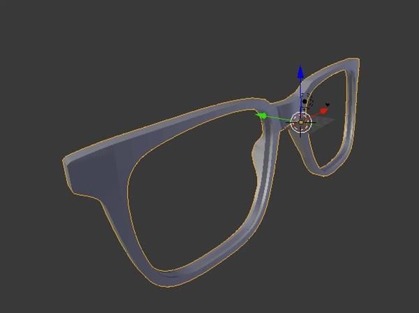
This method of modeling is quite intuitive because the user can move edges and points in space to deform the model until arriving at the desired shape. It also allows to have a greater complexity than through surface processes. On the other hand, it does not offer the best dimensional accuracy because the 3D model is the result of successive subdivisions. This is a major obstacle when it comes to obtaining a stable geometry for additive manufacturing.
Software features for 3D printing
We won’t go back over all of Blender’s features (animation, video, 3D rendering, etc.) because it’s really the 3D modeling part that interests us for 3D printing. You should know that the software offers export formats for additive manufacturing such as STL file but also OBJ file. However, polygonal modeling does not seem to be the most intuitive way to design printable parts. Blender still offers a feature to be added to its software called “3D Printing ToolBox”. This will allow you to analyze your mesh to identify some errors that could cause your printing to fail. For example, this toolbox can check the minimum thickness of your walls or the geometry of overhangs.
The ‘3D printing toolbox’ enables you to check your model before 3D printing
Blender is therefore not the 3D software most used by 3D printing enthusiasts but it has the merit of being free, open-source and regularly improved by its entire community. We recommend a software more accessible to all beginners like TinkerCAD for example, and Fusion 360 for the most experienced. You can download Blender HERE, the solution is compatible on Mac, Windows or Linux.
Do you use Blender? Let us know in a comment below or on our Facebook and Twitter pages! Sign up for our free weekly Newsletter, all the latest news in 3D printing straight to your inbox!
Blender Tutorials - Learn Blender
Have you been thinking about learning how to use Blender, but you open the window and see all this and get really confused? Well I’m here to help with that. My name’s Kevin, founder of Inventimark and I hope you enjoy these tutorials.
Blender Introduction Tutorial #001 The Basics
This tutorial is where you want to start when learning 3D modeling with Blender for 3D printing. Here you are shown the basics of Blender and the basic workings of the program. It’s a small step into the vast possibilities of the computer 3D world.
Introduction Tutorial #002 The Basics part 2
In this second part of this tutorial, you will learn about the different camera views and how each of them work. You will also be shown the most common keyboard shortcuts that are very helpful in creating a fast work flow to 3D Modeling.
Tutorial #003 Making a Simple Glass
In this modeling practice, you are taught how to make a simple glass. There is also an explanation of some of Blenders other features, showing you how to render your model to get a good picture of it.
Tutorial #004 Making an Action Cam Clamp
This modeling practice lesson will teach you some of the basic modeling techniques and uses, to make a practical design that can be used in the real world when printed.
Tutorial #005 3D Printing Functions
This tutorial demonstrates Blenders 3D printing specific features. Non-Manifold objects are also explained and why they are important to avoid.
Tutorial #006 More Basics of the UI
This lesson explains in more detail some of the user interface to get you more familiar with using it.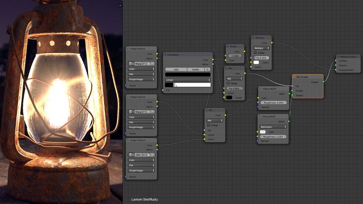 Also shown is the sculpting features and some abstract modeling is made to demonstrate its uses.
Tutorial #007 : Loop tool and Proportional Editing
This tutorial shows you how the edge cut tool works. Also shown is how proportional editing works to make object re-shaping smoother.
Tutorial #008 : Pivots and Startups
In this tutorial, the pivot point/origin is shown, as well as how to save the startup files to keep your settings.
Tutorial #009 : Project box
In this tutorial, is another practicing session on practical 3D modeling. Shown is a project box for a solar powered automatic watering system using several different components.
Tutorial #010 Nurbs Curves and Surfaces
In this video, examples of using curves to model are shown. Also featured is how to make solid objects and how to mirror objects.
Tutorial #011: Text Basics
This tutorial shows the text features in Blender, and how to integrate text into your models.
Tutorial #012 : Measurements
This video explains the different measurements in Blender that can be used. Examples are show with Unity, Unreal Engine 4, and Repetier-Host. This video also explains that Blender units as 1mm are the best to use for 3D modeling.
Tutorial #013 : Background Image + Bonus
This video demonstrates how to use a background image to get a precise model from an image. Shown as example is an E3D-V6 hot-end heat sink. The image used was acquired from http://wiki.e3d-online.com/.
Tutorial #014 : Practical Modeling Practice
This is a longer practical modeling practice showing how to make a linear bearing with 3x8x4mm bearings and M3 bolts and nuts. There are errors and troubleshooting to show how to deal with that as well.
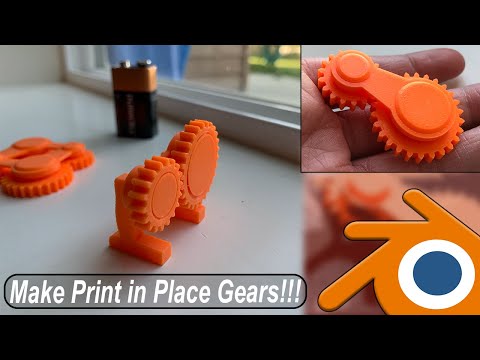
Tutorial #015 : How to Make Gears
This video demonstrates how to make gears for a 3D printer extruder. This process can be used whenever any 2 gears are used.
Tutorial #016 : Loop Tools
This video demonstrates all of the Loop Tools and how they are used. Some of these tools are great for 3D printing, others are rarely used.
Tutorial #017 : Splitting Model for 3D print
This video demonstrates a crudely made model and how to split the model up into different parts for easier printing. This will for for any size model.
Tutorial #018 : Knife Tool
This video shows a model of a Bowie knife the author made. What is taught in this tutorial, is how to use the knife tool and shows what it does as well as other knife features.
Tutorial #019 : Torture Calibration
This video is another practical modeling practice that shows you how to make a calibration/torture test for your 3D printer to get the dimensions correct.
Blender 3D for 3D Printers / Sudo Null IT News
Correct position! But some problems can still be covered by polygonal modeling.
Gathered here the answers to the four most common and non-obvious problems.
Dimensions
When I first tried to order 3D printing from a company about seven years ago, it was like this:
— Igor! You sent an empty file!
- No! Here's a screenshot, well!
One meter in the Blender is equal to one millimeter in the slicer, nothing has changed in these seven years.
Designing in meters is wonderfully inconvenient, so when exporting to STL/OBJ, set the Scale value to 1000:
Closed geometry The ability to create open geometry is both a scourge and a bonus of polygonal modeling.
In the modern world, slicers (not all) have learned how to work with this, but there may be surprises: want a hole? get a blank wall!
If you don't like surprises, you should use Blender's geometry analyzer.
In mesh edit mode, select vertex selection, and click Select → Select All By Trail → Non Manifold
To eliminate such trash as on the right ball, there is a Merge By Distance tool.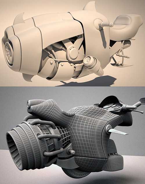 Lives in Mesh → Clean Up → Merge By Distance.
In other cases, it is necessary to either give the wall thickness by extruding, or close up the hole, or is this geometry really necessary?
And now for the good news: in Blender 2.8 the 3D printing addon is built right into Blender, hooray! Geometry analysis just got easier. You just need to turn it on, and in the edit mode in the N-panel everything will be (and even the preliminary volume of the model!).
Flying geometry
As unclosed, only flying. So the slicer can still try to shove it into the G-code!
The annoyance is that if the volume of the walls was made by a modifier, these mesh pieces can no longer be found with the Non Manifold tool.
Select any polygon on the target mesh, and use the Ctrl+L hotkey: it will add all physically connected polygons to the selection. After that, invert the selection with the Ctrl+I hotkey and delete everything you don't need.
Normals
Roughly speaking, the polygon has a "face". When the polygon enters the slicer, the slicer looks at where the polygon has a “face”, tries to fill the wrong side with plastic, and at the same time checks for overhangs.
Accordingly, a cube with normals inside will be perceived clumsily. In fairness, in modern slicers this is no longer so important.
The solution is super-simple: turn on the display of normals:
Flip in the right direction: select the polygon with the normal turned inside out and press Alt+N. Hoba! and the slicer no longer panics about negative angles where they cannot exist.
Generalize
Blender, indeed, is not developed as engineering software, and you should not try to solve furious tasks with it in the spirit of multicomponent kinematic systems.
But the blender + home 3D printer perfectly covers the needs of a small workshop, the main thing is to remember the nuances of polygonal modeling.
Blender 3D Printing: Creating the Right Model
Want to use Blender for 3D printing? Then this article is for you. Today we will look at the preparatory work and the basic principles of creating models suitable for 3D printing in Blender.
1. Preparing the program for work
Setting the scale and units of measurement
By default, Blender uses its own units of measurement, which have no analogue in the real world. This is quite suitable for creating virtual worlds (games, animation, illustrations), but for 3D printing it is important for us to have familiar units of measurement. Therefore, to start on the properties panel ( Properties ) in the scene tab ( Scene ) find the section with units ( Units ) and select metric units ( Metric ). Now one internal unit (unit) in Blender will be equal to 1 m . Parameter Scale ( Scale ) allows you to increase or decrease this ratio for the entire scene. Thus, the unit in Blender can be made equal to 1 cm or 1 mm . You can see and change the size of the current object on the object properties panel (accessible by pressing N ).
Activating Required Add-ons
This tutorial will use some specific Blender add-ons, so it's important to activate them beforehand. To do this, open the user settings window ( Ctrl + Alt + U ) and go to the addons tab ( Addons ). Use the search bar at the top left of the window to find the add-ons you need.
Find and activate the following two additions: Looptools and 3D Print Toolbox . To keep these add-ons active on subsequent launches of Blender, click on the button Save User Settings .
2. Polygon modeling for 3D printing
Important Tips for Creating Printable 3D Models
When you are modeling for 3D printing, there are a few rules that it is highly recommended to follow to ensure that your model will be printable. We list the most important of these rules below.
Create a closed model
To understand the concept of a closed model, we used the illustration below as an example. The 3D model on the left is not a closed volume, but a series of open surfaces with zero thickness. This will cause problems in most 3D printing programs, as they cannot print objects without a given volume and thickness. And the existence of physical objects with zero thickness in the real world is simply impossible. At the same time, such models may well exist in animation and other virtual environments, so such shortcomings are quite common.
To make sure your model is 3D printable, it is very important to close any random holes in it. To do this, you can select all the edges of the unclosed "hole" and press F - a polygon will be created in place of the hole. It is also usually useful in these cases to extrude next and then press Alt + M to merge the model. To close any holes it is also possible to use Ctrl + F and operation Grid Fill .
Avoid overlapping surfaces.
In the illustration below, you can see two surfaces belonging to two different volumes, but superimposed on each other. This can confuse many 3D printing programs. To avoid problems, it is necessary to merge the volumes into one and remove all superimposed surfaces. If the model has a complex geometry, you can use the Boolean operations modifier ( Boolean ) for this purpose.
Preserve the overall topology while minimizing the number of polygons
To reduce the file size and improve the usability of the model, it often makes sense to minimize the number of polygons in the model. The example below uses Surface Subdivision Modifier to smooth the surface. For similar purposes, you can also use modifiers Decimate or ReMesh .
Avoid thin and long features in
It is important to understand the physical properties and technical limitations of the materials used in a 3D printer. You need to be sure that all elements of the model can physically be printed.
In the picture below you can see the beetle model (top view, it is available in Blender by pressing the 5 key on the numpad). You can see parts (clipped in red) that will be less than 1 mm thick when printed . Naturally, when printing such details, problems can arise. When modeling, it is important to always keep in mind the minimum thickness allowed for printing with specific materials (it can be different for different materials and technologies). Often 3D printing software and services will let you know about these potential problems before printing, but it's best to take care of this in advance, during the modeling phase.
3D modeling tools
Blender's 3D modeling tools are very numerous and varied. We present here only the most used and well-known ones. Before using them, do not forget to switch to edit mode (key Tab ).
- Insert ( Insert , I ):
- Creates a loop around the selected faces.

- Straight extrusion ( Instant Extrude , Ctrl + LMB ):
- Extrude (extrusion) the selected area.
- Knife ( Knife , K ):
- Allows you to arbitrarily cut the model along the specified lines.
- Chamfer ( Bevel , Ctrl + B ):
- Chamfers (rounds edges) selected parts of the model. Be aware that these bevels may become flaky during the printing process.
- Grid Fill ( Grid Fill Ctrl + F ):
- Fills missing surfaces with a mesh. This tool is ideal for closing voids in a model before printing. Alternatively, you can also try the tool available by clicking on F (with vertices selected).
- Edge connection ( Bridge Edge , Ctrl + E ):
- Adds missing faces between edge loops.
 This tool is most effective when two connected loops have the same number of vertices. Convenient for connecting two separate parts of the grid into a single whole.
Preparing text and curves for 3D printing
Consider the example of preparing text for 3D printing. First, add a text object to an empty scene.
By default, such a text object is a simple surface with zero thickness. Naturally, for printing, we need to add thickness to this object. To do this, on the properties panel ( Properties ) on the Text tab in the Geometry section, enter a non-zero value in the Extrude field (for example, 0.1 ). Increase or decrease this parameter to achieve the desired result.
The volume has been added, but the letters are still not connected to each other, that is, when printed, they will fall apart into separate objects. To prevent this from happening, let's create a background for our text. In the example, we use a Bezier curve for this purpose, but you can use any other option.
So create a Bezier circle ( Shift + A → Curve → Circle ). Change the scale ( S ) along the required axes and move ( G ) the curve to the desired location. Keeping the curve selected, on the properties panel ( Properties ) on the properties tab of curves in section Shape activate item 2D .
Just like for the text, in the Geometry section, enter the desired value in the Extrude field (experiment until you achieve the desired result.
Once the geometry is ready (you can still play with the position along the axes, chamfers, etc.), it's time to prepare for the export, since Blender only exports polygons, the first thing you need to do is convert the model to a single mesh.Use combination Alt + C to convert curve to mesh. Then do the same for the text.
Duplicate vertices may appear when converting to a mesh. They can be combined in edit mode. To do this, select all the vertices ( A ), press Ctrl + V and select Remove Doubles from the menu that appears ( Remove Doubles ). And don't forget to recalculate the normals of all faces after that for their outward orientation ( Ctrl + N ).
To combine multiple objects into a single mesh, you can select them and press Ctrl + Shift + Numpad+ .
Your object is now ready to be exported for 3D printing.
3. Practice of Using Blender Modifiers in 3D Printing
When used correctly in Blender, modifiers are applied to the model in an interactive and non-destructive way. In this case, in the edit mode, you can continue to work with the unmodified mesh. As everyone is well aware, modifiers can be added in tab Modifiers (with a wrench icon) in the properties panel. And now we will analyze some of the nuances of using modifiers when preparing a model for 3D printing.
Modifier
Mirror (mirror reflection)This modifier is used very often to create symmetrical models. However, when using it in the 3D printing process, some problems may arise.
Make sure that the axis of symmetry is in the same plane as the center hinge of the model. Once you have decided on this central loop, check the checkbox Clipping in the modifier properties (on the properties panel). This will prevent the vertices from crossing the plane of symmetry (their "climbing" to the "foreign" side).
It is also good practice to place the reflection modifier first in the modifier stack.
Again, when using the reflection modifier, it's important to remove any internal edges that appear after applying the modifier. As mentioned earlier, these edges can lead to problems in 3D printing.
Decimate the number of faces: modifiers
ReMesh and DecimateModifier
ReMesh Modifier ReMesh rebuilds the mesh topology without modifying the actual geometry of the model. This modifier can be applied to models that have an excessive number of faces, or if the faces are not uniform. Such problems often arise when importing models from other programs, or when dynamically sculpting.
Modifier
DecimateAgain, if you want to reduce the file size and make it easier to export, the Decimate modifier can reduce the number and density of faces. Compared to modifier ReMesh , modifier Decimate more closely follows the original geometry of the model, but not the topology.
Adding thickness to a surface: Solidify modifier
Solidify modifier adds thickness to a surface. Parameter Thickness specifies the thickness of the object in internal Blender units. It is the ideal tool for creating printable models from a series of surfaces.
Check the box Even Thickness in the modifier settings if your model has well defined corners.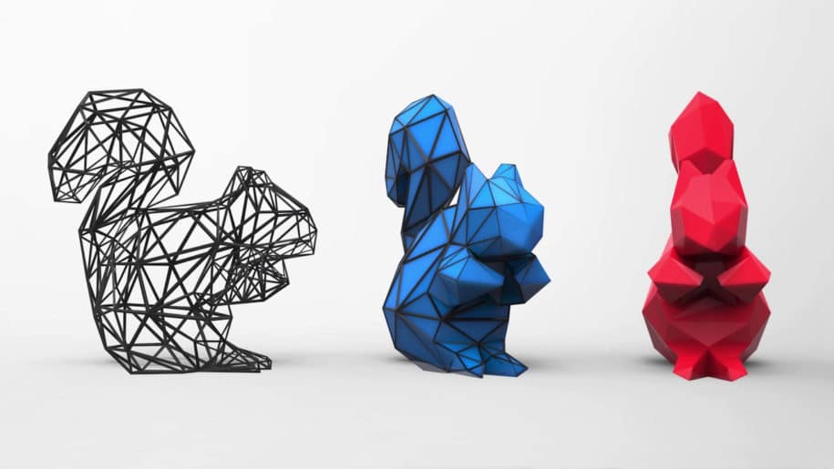 This setting optimizes the thickness for all geometry in your model and avoids brittle areas.
Snapping one geometry to another: modifier
ShrinkwrapModifier Shrinkwrap allows you to "glue" a given surface to another model. Using it in conjunction with the Solidify modifier, you can create clothes and other accessories that need to be attached to a character or other object. To avoid overlapping surfaces, make sure that the value of parameter Offset for modifier Solidify is 0 .
Adjustment of multiple geometry and intersections: modifier
Boolean The Boolean modifier allows you to perform boolean operations between two objects in a non-destructive way. This functionality is ideal for creating various holes, slots, cutouts, etc. in models, or for removing overlapping parts of two objects (which can otherwise cause printing problems).