Multi jet fusion 3d printing
Multi Jet Fusion (MJF) | 3D Printing
Back
-
Materials
Materials by Service
Injection MoldingCNC Machining3D PrintingSheet Metal
Materials by Type
PlasticsMetalsElastomers
Related Links
Customer Supplied ResinsColors
Injection Molding Material Alternatives Guide
Struggling with thermoplastic material shortages? We created a detailed guide to resin substitutes for ABS, PC, PP, and other commonly molded thermoplastics.
Download
-
Resources
Design Tips Guides and Trend Reports Success Stories Design Aids Webinars and Trade Shows
Blog Videos FAQs Educators and Students Glossary
Industries Medical Aerospace Automotive Consumer Electronics Industrial Equipment
-
About Us
Who We Are Why Protolabs? Research and Development Cool Idea Award Partnerships Sustainability and Social Impact
Careers Investors Locations Press Procurement
Contact Us
Proto Labs, Inc.
5540 Pioneer Creek Dr.
Maple Plain, MN 55359
United StatesP: 877.479.3680
F: 763.479.2679
E: [email protected]Best-in-Class Online Quoting
After uploading your part design, you'll receive an online quote that includes manufacturing analysis to help improve part manufacturability. Within your quote, you can also adjust quantity and material and see price changes in real-time.
Learn More
Get a QuoteSign In
MJF 3D printing builds quality nylon parts suitable for rapid prototyping and production.
Upload a Part
Certifications
ISO 9001:2015 | AS9100D
Jump to Section→ Capabilities
→ MJF Materials
→ Compare Material Properties
→ Surface Finishes
→ Our MJF 3D Printers
→ What is Multi Jet Fusion 3D Printing?
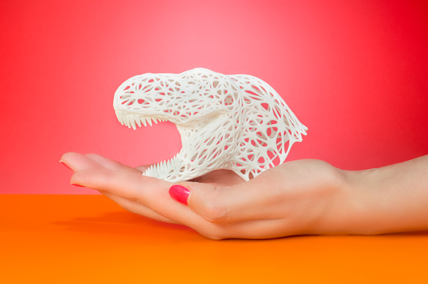
Multi Jet Fusion is an industrial 3D printing process that produces functional nylon prototypes and end-use production parts in as fast as 1 day. Final parts exhibit quality surface finishes, fine feature resolution, and more consistent mechanical properties when compared to processes like selective laser sintering.
Common applications for Multi Jet Fusion are:
- parts requiring consistent isotropic mechanical properties
- functional prototypes and end-use parts
- complex and organic geometries with fine features
If you have any issues getting your guide, click here to download.
Multi Jet Fusion Booklet
This 104-page comprehensive booklet on HP’s Multi Jet Fusion Service, provides must-have insight into best practices and in-depth design guidelines on how to best produce your part using this technology.
United States of AmericaAfghanistanÅland IslandsAlbaniaAlgeriaAmerican SamoaAndorraAngolaAnguillaAntarcticaAntigua and BarbudaArgentinaArmeniaArubaAustraliaAustriaAzerbaijanBahamasBahrainBangladeshBarbadosBelarusBelgiumBelizeBeninBermudaBhutanBolivia, Plurinational State ofBonaire, Sint Eustatius and SabaBosnia and HerzegovinaBotswanaBouvet IslandBrazilBritish Indian Ocean TerritoryBrunei DarussalamBulgariaBurkina FasoBurundiCambodiaCameroonCanadaCape VerdeCayman IslandsCentral African RepublicChadChileChinaChristmas IslandCocos (Keeling) IslandsColombiaComorosCongoCongo, the Democratic Republic of theCook IslandsCosta RicaCôte d'IvoireCroatiaCubaCuraçaoCyprusCzech RepublicDenmarkDjiboutiDominicaDominican RepublicEcuadorEgyptEl SalvadorEquatorial GuineaEritreaEstoniaEthiopiaFalkland Islands (Malvinas)Faroe IslandsFijiFinlandFranceFrench GuianaFrench PolynesiaFrench Southern TerritoriesGabonGambiaGeorgiaGermanyGhanaGibraltarGreeceGreenlandGrenadaGuadeloupeGuamGuatemalaGuernseyGuineaGuinea-BissauGuyanaHaitiHeard Island and McDonald IslandsHoly See (Vatican City State)HondurasHong KongHungaryIcelandIndiaIndonesiaIran, Islamic Republic ofIraqIrelandIsle of ManIsraelItalyJamaicaJapanJerseyJordanKazakhstanKenyaKiribatiKorea, Democratic People's Republic ofKorea, Republic ofKuwaitKyrgyzstanLao People's Democratic RepublicLatviaLebanonLesothoLiberiaLibyaLiechtensteinLithuaniaLuxembourgMacaoMacedonia, the Former Yugoslav Republic ofMadagascarMalawiMalaysiaMaldivesMaliMaltaMarshall IslandsMartiniqueMauritaniaMauritiusMayotteMexicoMicronesia, Federated States ofMoldova, Republic ofMonacoMongoliaMontenegroMontserratMoroccoMozambiqueMyanmarNamibiaNauruNepalNetherlandsNew CaledoniaNew ZealandNicaraguaNigerNigeriaNiueNorfolk IslandNorthern Mariana IslandsNorwayOmanPakistanPalauPalestine, State ofPanamaPapua New GuineaParaguayPeruPhilippinesPitcairnPolandPortugalPuerto RicoQatarRéunionRomaniaRussian FederationRwandaSaint BarthélemySaint Helena, Ascension and Tristan da CunhaSaint Kitts and NevisSaint LuciaSaint Martin (French part)Saint Pierre and MiquelonSaint Vincent and the GrenadinesSamoaSan MarinoSao Tome and PrincipeSaudi ArabiaSenegalSerbiaSeychellesSierra LeoneSingaporeSint Maarten (Dutch part)SlovakiaSloveniaSolomon IslandsSomaliaSouth AfricaSouth Georgia and the South Sandwich IslandsSouth SudanSpainSri LankaSudanSuriNameSvalbard and Jan MayenSwazilandSwedenSwitzerlandSyrian Arab RepublicTaiwan, Province of ChinaTajikistanTanzania, United Republic ofThailandTimor-LesteTogoTokelauTongaTrinidad and TobagoTunisiaTurkeyTurkmenistanTurks and Caicos IslandsTuvaluUgandaUkraineUnited Arab EmiratesUnited KingdomUnited States Minor Outlying IslandsUruguayUzbekistanVanuatuVenezuela, Bolivarian Republic ofViet NamVirgin Islands, BritishVirgin Islands, U.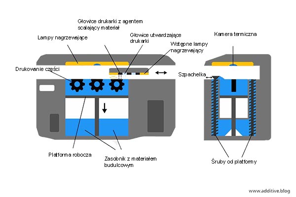 S.Wallis and FutunaWestern SaharaYemenZambiaZimbabwe
I agree to receive email messages containing service updates and Design Tips from Protolabs and its affiliates
Design Guidelines for Multi Jet Fusion
Our basic guidelines for Multi Jet Fusion include important design considerations to help improve part manufacturability, enhance cosmetic appearance, and reduce overall production time.
| US | Metric | |
| Maximum Part Size | 11.1 in. x 14.9 in. x 14.9 in | 284mm x 380mm x 380mm |
| Layer Thickness | 0.00315 in. | 80 microns |
| Minimum Feature Size | 0.020 in. | 0.5mm |
| Wall Thickness | 0.020 in. | 0.5mm |
Tolerances: For well-designed parts, tolerances of +/- 0. 012 in. (0.30mm) plus 0.1% of nominal length for each additional inch can typically be achieved. Note that tolerances may change depending on part geometry.
Warpage: Larger part sizes (>7 in.) and parts with thin features are the most susceptible to warp. We recommend maintaining a uniform thickness of 0.125 in. (3.175mm) to ensure stability.
MJF Material Options
PA 12 Black
PA 12 Black is a high tensile strength nylon. Final parts are dyed black, and they exhibit quality surface finishes and slightly more isotropic mechanical properties when compared to SLS. When more detail is required, PA 12 can achieve smaller minimum feature resolution (0.02 in) as compared to SLS materials (0.03 in). PA 12 Black is the best material option for designs that incorporate living hinges.
Primary Benefits
- Near isotropic mechanical properties
- Economical material choice
PA 12 40% Glass-Filled Black
PA 12 40% Glass-Filled Black is a 40% glass-filled nylon.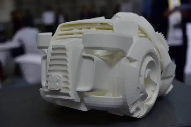 Final parts are dyed black. The biggest advantage offered by this material is heat deflection at 347°F (measured at 66 psi), ranking 2nd best after PA 12 Mineral-Filled.
Primary Benefits
- Economical material choice
- Heat deflection
Compare MJF Material Properties
- US
- Metric
| Material | Color | Tensile Strength | Tensile Modulus | Elongation |
|---|---|---|---|---|
| PA 12 Black | Black | 7.1 ksi | 276 ksi | 8.5% |
| PA 12 40% Glass-Filled Black | Black | 4.35 ksi | 508 ksi | 8.5% |
| Material | Color | Tensile Strength | Tensile Modulus | Elongation |
|---|---|---|---|---|
| PA 12 Black | Black | 49 Mpa | 1,900 Mpa | 8. 5% 5% |
| PA 12 40% Glass-Filled Black | Black | 30 Mpa | 3,500 Mpa | 8.5% |
These figures are approximate and dependent on a number of factors, including but not limited to, machine and process parameters. The information provided is therefore not binding and not deemed to be certified. When performance is critical, also consider independent lab testing of additive materials or final parts.
Multi Jet Fusion Surface Finish
| Standard | A bead blast removes all powder and leaves a consistent overall texture. Parts are then dyed a standard black color. |
| Custom | Secondary options include a primer that can be applied as well as taps and inserts. |
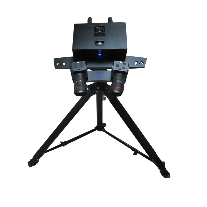
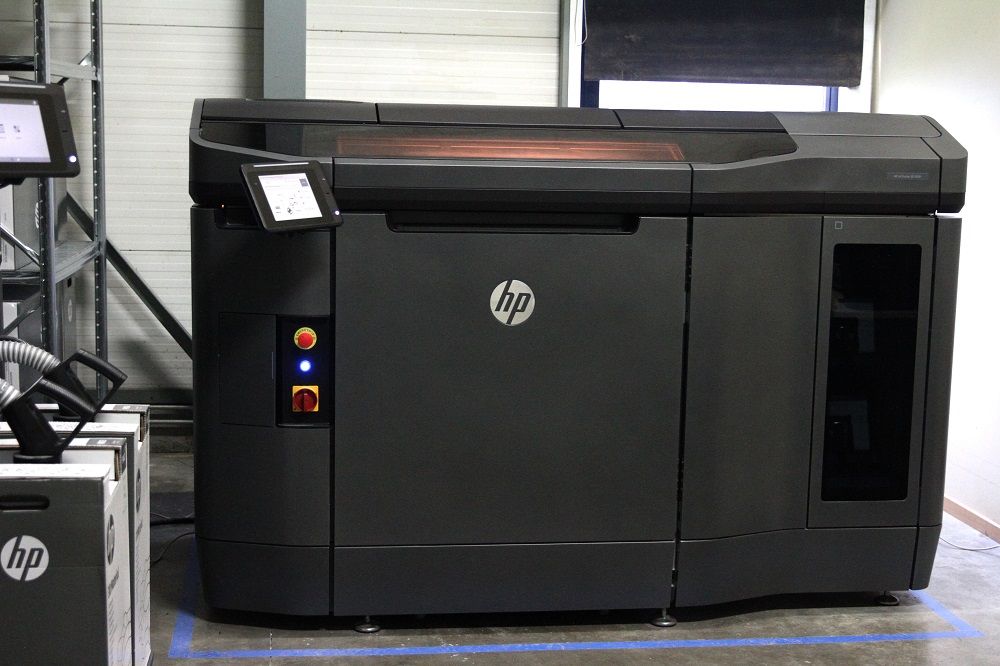
Our MJF 3D Printers
We use HP Jet Fusion 3D 4210 and 5210 machines that are capable of accelerated build speeds when compared to other powder-based additive manufacturing technology. The HP 3D printers produce commercial-grade parts with enhanced surface finishes and improved mechanical properties compared to other 3D printing technology.
Why Use Multi Jet Fusion?
See how 3D printing with Multi Jet Fusion is ideal for functional prototypes and end-use, production parts.
How Does Multi Jet Fusion Work?
Multi Jet Fusion uses an inkjet array to selectively apply fusing and detailing agents across a bed of nylon powder, which are then fused by heating elements into a solid layer. After each layer, powder is distributed on top of the bed and the process repeats until the part is complete.
When the build finishes, the entire powder bed with the encapsulated parts is moved to a processing station where a majority of the loose powder is removed by an integrated vacuum. Parts are then bead blasted to remove any of the remaining residual powder before ultimately reaching the finishing department where they are dyed black to improve cosmetic appearance.
Resources
Design Tip
How to Use Multi Jet Fusion for Functional 3D-Printed Parts
Create functional prototypes and end-use production parts with HP’s 3D printing technology.
Read Design Tip
Blog
MJF vs. SLS: A Comparison of Polyamide 3D Printing Technologies
A look at the key differences between Multi Jet Fusion and selective laser sintering and how to determine the optimal process for your application.
Read Blog
Success Story
OVR Technology
The medtech startup used Multi Jet Fusion (MJF) for prototyping as well as low-volume production for its pioneering product the OX1—a lightweight, scent-emitting device that attaches to the bottom of a VR head-mounted display.
Read Success Story
Guide
3D Printing Materials: Select the Right Plastic or Metal for Your 3D-Printed Part
Explore material properties available for plastic and metal 3D printing processes
Read Guide
Get an instant quote on your 3D printing design.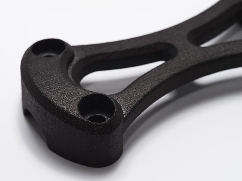
UPLOAD A PART
Industrial 3D Printer – HP Jet Fusion 5200 Series 3D Printing Solution
The content of this site is for information purposes only and it is showing the product configuration for the US market only.
Availability, pricing, product configuration and specifications may differ according to geographical location, local laws and practices.
Please contact us or talk to your local HP 3D Printing representative for further information or for product configurations specific to your local country.
1. Available only for the HP Jet Fusion 5200/4200 Series 3D Printing Solutions.
2. Supported industrial management systems: 3D Control Systems, AMFG, LINK3D, Siemens NX AM, Siemens Opcenter. Access to additional data modules available only for the HP Jet Fusion 5200 Series 3D Printing Solution. Additional purchases required.
3. Compatible software. Additional purchase required.
4. Available only for the HP Jet Fusion 5200 Series 3D Printing Solution. This software is sold as an HP 3D Solution Service. For more information visit https://h30195.www2.hp.com/v2/GetDocument.aspx?docname=4AA7-7931EEW
5. Based on internal HP testing, May 2020. HP Jet Fusion 3D Printing Solutions using HP 3D High Reusability PP enabled by BASF provide up to 100% powder reusability ratio, producing functional parts batch after batch. For testing, material is aged in real printing conditions and reclaimed powder is tracked by generations (worst case for reusability). Parts are then made from each subsequent generation and tested for mechanical properties and accuracy showing no degradation of properties up to three generations of use.
6. Based on internal HP testing, May 2020, with tests for mechanical property retention, dimensional stability, and weight change after 7- and 30-day immersion with acids, bases, organic solvents, and aqueous solutions. Due to the material characteristics, extra tuning is required in part design and printing, compared to other rigid HP 3D Printing materials.
7. HP 3D High Reusability PA 11 image is data courtesy of NACAR
8. HP Jet Fusion 3D Printing Solutions using HP 3D High Reusability PA 11 provide up to 70% powder reusability ratio, producing functional parts batch after batch. For testing, material is aged in real printing conditions and powder is tracked by generations (worst case for reusability). Parts are then made from each generation and tested for mechanical properties and accuracy.
9. Testing according to ASTM D638, ASTM D256, and ASTM D648 using HDT at different loads with a 3D scanner for dimensional accuracy. Testing monitored using statistical process controls.
10. HP 3D High Reusability PA 12 image is data courtesy of Addit.ion.
11. HP Jet Fusion 3D Printing Solutions using HP 3D High Reusability PA 12 provide up to 80% powder reusability ratio, producing functional parts batch after batch. For testing, material is aged in real printing conditions and powder is tracked by generations (worst case for reusability). Parts are then made from each generation and tested for mechanical properties and accuracy.
12. Supplies price, and maintenance costs recommended by manufacturer. Cost criteria: printing 1.4 full build chambers of parts per day/5 days per week over 1 year of 30 cm3 parts at 10% packing density on Fast print mode using HP 3D High Reusability PA 12 material, and the powder reusability ratio recommended by manufacturer, and printing under certain build conditions and part geometries.
13. HP 3D High Reusability PA 12 GB image is data courtesy of NACAR
14. HP Jet Fusion 3D Printing Solutions using HP 3D High Reusability PA 12 Glass Beads provide up to 70% powder reusability ratio, producing functional parts batch after batch. For testing, material is aged in real printing conditions and powder is tracked by generations (worst case for reusability). Parts are then made from each generation and tested for mechanical properties and accuracy.
15. BASF Ultrasint® TPU01 image is data courtesy of Kupol.
16. This product is only available in Europe and in the Americas. HP does not design, manufacture or sell the Girbau product or provide any warranty for the Girbau products. HP believes that the information herein is correct based on the current state of scientific knowledge and as the date of its publication, however, to the maximum extent permitted by law HP EXPRESSLY DISCLAIMS ANY REPRESENTATIONS AND WARRANTIES OF ANY KIND, WHETHER EXPRESS OR IMPLIED, AS TO THE ACCURACY, COMPLETENESS, NON-INFRINGEMENT, MERCHANTABILITY AND/OR FITNESS FOR A PARTICULAR PURPOSE (EVEN IF HP IS AWARE OF SUCH PURPOSE) WITH RESPECT TO ANY INFORMATION PROVIDED. Except to the extent that exclusion is prevented by law, HP shall not be liable for technical or editorial errors or omissions, and damages or losses of any kind or nature that result from the use of or reliance upon this information, which is subject to change without notice. Recipients of the Girbau product are responsible for determining the suitability of Girbau products with HP Jet Fusion 3D products, ensuring compliance with applicable laws and regulations, and being aware that other safety or performance considerations may arise when using, handling or storing the pro.
17. Data courtesy of Meidai
Start printing directly from Fusion 360
Although many people are skeptical about the slicing functionality in Fusion 360, I have only been using it since its release (I think March 2020). In the next few articles, I want to tell you exactly what you need to do in order to get the G-code of your model directly from the fusion.
In the first part, I will outline the algorithm of actions for generating code in large blocks. Then we will do an interactive stream, and after that there will be one or more articles detailing the incomprehensible steps.
First, the model itself is needed. We assume that the part is already made, saved in one of the projects in the cloud and ready for printing.
Next we have to go into Manufacture mode, just click on Design and select Manufacture there. We will find ourselves in a new mode of operation with the same model.
Once again, an important thought - the model does not change, it is not transferred / uploaded / exported anywhere.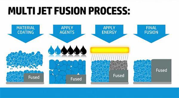 The geometry remains the same, we just change the mode of working with it and the tools.
Cool fact #1 - printing from fusion makes it possible not to export / import the model, we do not divide the model into the "solid state for editing", "stl for printing" stages. Within the same system, we work with the same model with different tools. We simply switch between Design/Manufacture modes and, accordingly, alternately get model editing tools and code generation tools
After switching to Manufacture, the concept 9 becomes key for us0015 Setup . This thing is well known to those who work on CNC machines, and we also have to deal with it.
When we are preparing the print, in the setup we need to put together the following information: we set it by creating in the library (once) and then selecting (each time when creating a setup) our printer ( Machine ).
For other CNC systems, the Machine setting is optional, but for printing (i.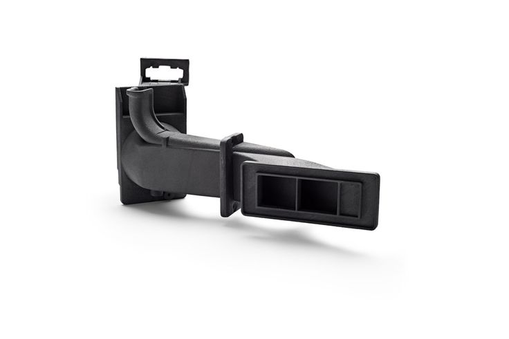 e. additive operations) it is critical. All machine descriptions are stored in the library. The car needs to be created in advance, before creating the first setup, but next time you can just select it from the library.
The following is written in the machine:
- the number and parameters of extruders
- the presence of airflow model
- table dimensions
- where to park the head after printing
- and, of course, the name and text description
In general, everything that describes the printer geometrically and gives an idea of its maximum capabilities.
A good practice to create your own machine is to (1) take one of the already prepared descriptions (2) copy it to your library and (3) fix it to fit your needs.
The library, for example, already has Ender 3. If your printer is not there, then just copy the default " Autodesk Generic FFF Machine ".
In my case, the set of edits was minimal - table dimensions, parking coordinates and description.
The second part of the setup, "what to print" - is indicated in paragraph Model and there you can select the entire model, component (or several)
Important fact #2 - if you are printing a multi-part model, you need to make sure that each part is in its own component.If this is not done, then fusion will work with the entire group as with one part and you will not be able to lay out individual parts on the table.Positioning tools - Move, Arrange, Automatic Orientation and Place part on platform work only with 9 components0017And finally, the third part of the setup, "with what settings to print" - this is called Print Settings and in organization this thing is very similar to Machine:
- they also need to be done in advance, before creating the setup
- they are also stored in the library
- you can also take them from the default ones, copy them to yourself and fix them
- you can also create as many as you need and then just select from the library
All print settings are stored in print settings:
9000 9000
- temperatures
- speeds
- or not (and which ones) - BRAM, SKIRT, RAFT, support
- Perimeters settings, filling
- and so on, and so on
Important fact #3 - PRINT settings can be changed directly inside the setup, these changes only affect the current setup.For example, you have an ABS profile with temperatures/speeds, but in this model you want the speeds to be different - you can easily change the settings after creating the setup and do not spoil the profile stored in the library
In total, when you put all three parts together and created a setup, you get this element
After that, you shamelessly use all the available tools for positioning parts, among which there is a wonderful Automatic Orientation, which I will talk about someday later
You change the print settings for this setup as you like without fear of damaging the saved profiles
And most importantly, you must do two things.
First, generate an extruder path ( toolpath ) for a given setup (i.e. machine + model + settings) process (3) trajectory is ready
Naturally, this procedure must be done every time you change something in the settings or setup. The rule is very simple, we see an exclamation mark - it means we need to regenerate the trajectory.

And the second important thing - you check the resulting trajectory in the built-in simulator. P-time:
Two:
Remarkable fact #4 - you can create as many setups for your model as you like. This may be necessary, for example, if you print different parts with different settings, I do this when some need to be printed with supports, and some without. We simply create a new setup, select only those components in it that should fall into it and set our own settings in the setupWhen you visually got what you need, only one step separates you from the G-code - post-processing .
The point is that the toolpath you see is not code yet. These are geometric lines, displaying the movement of the extruder, but not the code. The code is generated by a postprocessor, which is essentially a JavaScript program (but you don't need to understand these subtleties at all).
So, post-processing. When the toolpath is ready and you are satisfied, do this
Then like this:
Then like this
And that's it.
Press Post, show where to put the file, save. The code is ready.
In a nutshell, what we just did:
- select the library of pre-installed post processors
- select the default "Generic FFF Machine" post from it
- upload the code through this post processor
This whole process can be made easier, faster, better, etc. - you can make your own postprocessor and put it in your own library; you can specify in the Machine settings which post to use for your printer and where exactly to put the files with the code. And so on.
There are a lot of opportunities to flexibly bend the process to your liking.
After creating all the setups and settings, don't forget to save, because there is
Cool Fact #5 - fusion printing makes it very easy to iterate. After creating the setups and checking the settings, we can switch to Design mode and edit the model. After returning to Manufacture, we just need to click Generate toolpath to get new toolpaths for the modified model.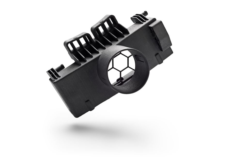
In order to discuss all this, I will organize a stream, where I will additionally present a custom post-processor, in which it is possible to use a second extruder to print the model and flexibly set the percentage of airflow 😊
That's all for now. Write in the comments what is not clear, come to the stream, ask questions.
3 Useful 3D Printing Applications for Fusion 360
Additive Assistant tool for Fusion 360
You've probably already explored the 3D printing capabilities of Fusion 360, and if not, you're missing out. From FFF printing to metal powder additive manufacturing, Fusion 360 tools are evolving at a rapid pace, with even more new features coming towards the end of the year. Today, we're sharing three useful 3D printing apps available on the Autodesk App Store to help you take your additive manufacturing work to the next level.
Fusion 360 FFF Post Configurator
Download here
What it is: is an application that allows you to create and configure FFF post processors.
Who: for anyone who wants to customize their device settings for printing with preset custom messages.
How it works: you can easily load custom settings for printer platform temperature, heat-up timeout, fan speed and other options. Since the result of the configurator is a traditional JavaScript post-processor, advanced users will be able to modify it.
Addition: Check out the application's tutorial for more useful information about its features.
Autodesk Netfabb® for Autodesk® Fusion 360™
Download here
What it is: If you want to seamlessly transfer Fusion 360 models to Netfabb, this application will help make the process as easy as possible.
In addition, with it you will be able to send all print settings to Netfabb and Netfabb Simulation, including printer selection, support data and placement of parts on the platform.
To whom: Of course, this application is for those who already have a Netfabb subscription. However, if you are using Fusion 360 and want to take your AM work to the next level, Netfabb is the perfect companion tool, providing many advanced features and capabilities for AM. Imagine that you started setting up metal powder printing with the Fusion 360 Additive build extension and manually edited the supports in Netfabb. With this application, you can easily transfer all your data from one program to another.
Addition: If you want to learn more about Netfabb, visit the product page on our website and don't forget to watch the video below.
Additive Assistant Tool
Download here
What it is: We've been saving the best for last.
Additive Assistant Tool allows you to analyze models without leaving Fusion 360: the application analyzes overhang angles, potential distortion and stability problems, can determine the size of the part, and also talk about the impact of its production on the environment.
How it works: Download the application, select the object you want to analyze, and the tool will automatically highlight problem areas that need your attention or need to be changed before being sent to print.
For whom: Any specialist will confirm that the human factor does not disappear with age and experience. The Additive Assistant Tool is a must for anyone new to additive manufacturing in order to understand what pitfalls to avoid, as well as experienced users. Often there are situations when 3D printing is used to create a prototype, and in the future the real product will be produced in a completely different way. In these situations, the Additive Assistant Tool will help ensure that the part prints with as few problems as possible.

Learn more