3D printing joints
3D Printed Joinery: Simplifying Assembly
Joinery is a term usually found in woodworking, referring to the practice of joining two pieces of wood together by geometrically constraining them. Good joinery provides strong connections with little-to-no help from fasteners like nails or screws. Joinery is useful because it ensures a strong connection with a less complicated assembly process. However, it usually involves complicated shapes that take time to design and create, while bolts and screws just require a hole and a mass-manufactured fastener.
A classic T-bridle joint, printed in Onyx
3D printing is in an interesting position as a fabrication method because printing complicated geometry is often no more expensive than printing a block. Instead, FDM printing is limited by material properties and the process of building in layers. Thus designing for 3D printing requires a new mindset, and part of that mindset is leveraging the geometric freedom of a 3D printer to reduce the complexity and cost of the final assembly. One way to do that is to look at joinery invented for wood working and injection molding and apply that to the constraints of 3D printing. In this blog, I discuss leveraging simple joints like dovetails and snap fits to improve your 3D printed joint designs, supplemented by some examples.
Dovetails
A classic dovetail joint
When it comes to constraining two parts, many people think in right angles. And this is efficient, especially when thinking about machining; right angles are generally much easier and faster to make than odd angles, requiring fewer setups and no special bits or indexing tables. To a 3D printer, however, dovetails and straight walls are all the same. With no extra effort, you can constrain another degree of freedom. This comes in handy everywhere, whether you want a sliding assembly or a fastener-less T-joint.
Sliding dovetail box, disassembled
The flared walls and tight tolerances allow this box to slide smoothly
When thinking in angles, bear in mind that the established dovetail shape isn’t the only application. The two-part sliding box shown above accomplishes the same restraint as a dovetail, but looks more like a plate with angled sides. This allows it to slide together with the other half of the box easily, and even includes a little detent at the end to snap it shut. This shape would be very hard to manufacture by most other means, but the Mark Two was able to 3D print joints without supporting materials and achieve a great fit.
Check out our Composites Design Guide
Exploring even further, angled geometry in general can help in 3D printing. For instance, printing a sideways V profile, shown below on the left, can create a constraint that would be difficult to machine, but is trivial to print. Meanwhile, a classic tongue and groove joint, as shown on the right, is hard for most printers to make because of the overhang it creates. This overhang results in a poorly supported bottom face with bad dimensional accuracy, and should be avoided if possible.
Profiles of a sideways V wall (left) and a tongue-and-groove joint (right)
Snap Fits
Snap fits are a commonly used method for cheaply joining injection molded parts.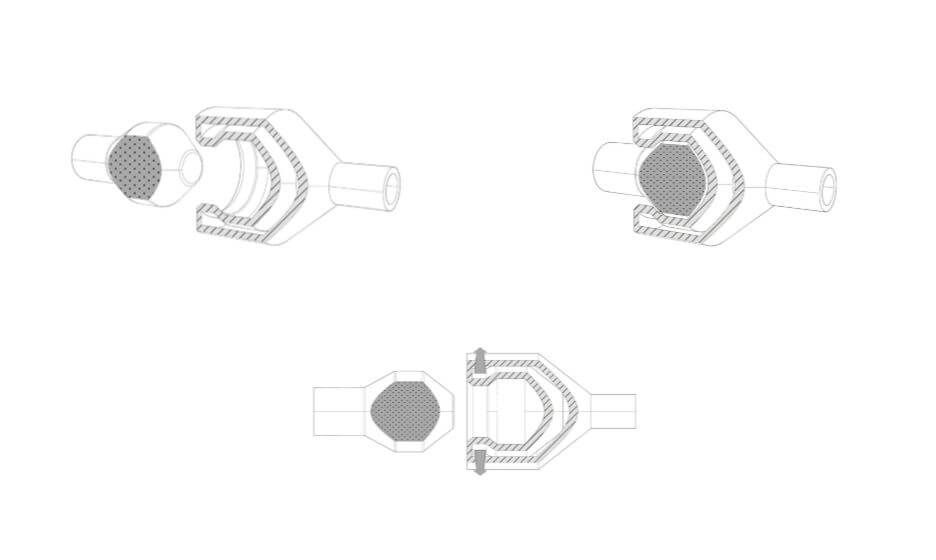 These are good shapes for plastics because they stay within the geometric constraints of mold making and use plastic’s ability to elastically deform and then snap back into shape. Because snap fits are designed for plastic, they are easily adopted for 3D printing…on the XY plane. Most 3D printer users know that objects printed on desktop FDM printers are significantly more susceptible to failure in tension along the Z axis (pointing out of the build plate) than in X and Y, because of the inter-layer boundaries. Since snap fits usually have thin cross-sections (to reduce bending moment of the clip), 3D printed snap fits must be printed “laying down” on the build plate, lest they risk shearing after repeated use.
Diagram of cantilever snap joint, printed in three possible orientations
This diagram shows an exaggerated visualization of the layers of a printed snap fit. When printed upright (pictured at left), the forces that deflect the snap fit also put tension between the layers, making it significantly more likely to break. Printed on its back (pictured at center), a snap fit will definitely be stronger, but still has a shear plane running between the tooth and the arm. Printed laying down on its side (pictured at right), however, the snap fit has no layer boundaries within its cross-section, giving it more predictable strength. And, if the snap fit is big enough, printing it on its side would allow fiber to be routed into the tooth, thereby utilizing the full strength of a Markforged part. This same rule applies for gear teeth, ratchet teeth, and any other protrusion that needs to hold significant load.
Request a free sample part
Bear in mind also that snap fits can take many forms based on application, and that the design and orientation of the snap fit may change based on your project. In particular, snap fits coming out of 3D printer are not constrained by thicknesses or mold shapes, so you can get creative with where you put them (see below). Printers make it quick and easy to prototype, so try a few geometries before settling on the final shape.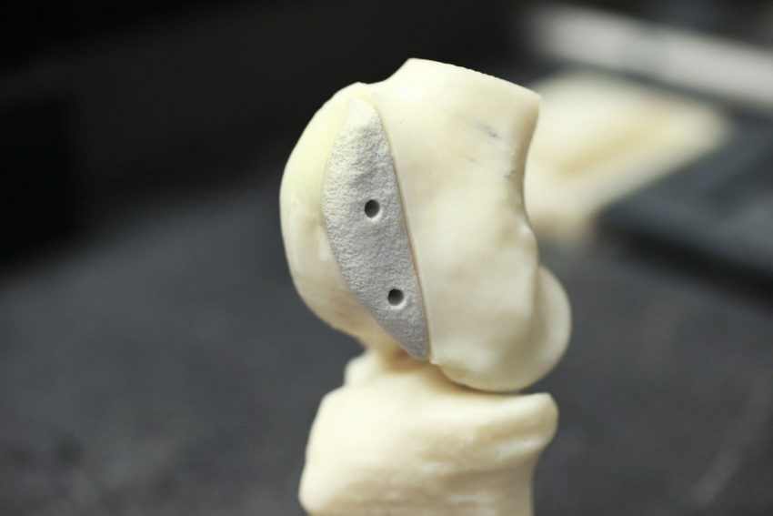
A flush snap fit mortise a ndtenon joint
Cross section of flush snap fit mortise and tenon
Putting it Together: Phone Holder
To exhibit sliding fits and snap mechanisms, I designed this cell phone holder that hooks over the hood of the Mark Two and holds any cell phone between 2.5 and 4 inches wide, so that an operator could take a time lapse video or monitor a sensitive print.
The phone holder with a phone in its grasp
This phone holder has just three parts, two interfaces. One of those interfaces is a twisting joint that acts as a hinge. Though it doesn’t look much like a dovetail, it serves the same purpose: it allows for an easily printable sliding fit, thanks to complementary angles.
Disassembled phone holder (left) and hook (right)
Rotating joint locking into place
The other interface works like a linear ratchet with angled walls (to keep them from slipping apart) and teeth to set the width of the holder. This would be a very difficult interface to machine make by most other means, but it was quite easy and quick to print!
The teeth of the linear ratchet with the corresponding face (right)
The linear ratchet for adjusting to phone width, engaged
The phone case in use, watching a Mark Two print
A Note on Tolerances
As with anything, joinery requires designing in your tolerances.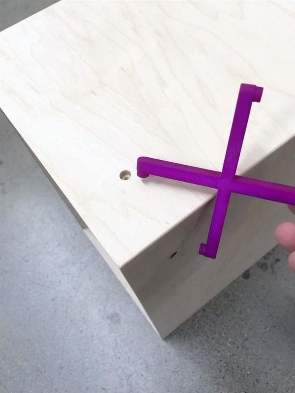 On the Mark Two composite 3D printer, for most general purposes, a .08mm gap between each wall (.16mm diametrically) is enough to allow two pieces to consistently achieve a sliding fit. If one of your surfaces is held up by support material, try bumping up the gap to .15mm or so. Of course, 3D printed parts tend to vary widely, so make sure to unit test and prototype to achieve the fit you want.
This is just one small example of how designing with joinery in mind can lead to designs that are simpler and better-fit for your 3D printer. As you find good joints for printing, tweet at us @MarkForged to share your designs!
3D Printing Joints
- 3D printing press fit parts
- 3D printed joinery
- Snap-fit joints for plastics
- Snap-fit design manual
- Buckle example
- 3D Printed Captured Nuts
- Fasteners and 3D printed parts
Sliding Fit Assembly – Applying traditional woodworking joinery to 3D printed parts.
- 3D guide to Joinery (twitter)
- 50 Digital wood joints
Press-Fit Assembly – Using the friction between two components to hold something in place. A good example for this are lego bricks. They have such a precise tolerance that pieces can snap and come apart with no problems.
Snap-Fit Assembly
Cantilever Snap joints – are the most common – Typically, a semi-flexible cantilevering hook is deflected slightly as it is inserted into a hole or past a latch plate. As the hook passes the edge of the hole, the cantilever beam returns to its original shape.
Annular snap joints – Great for circular applications – Classic examples of ASJs include ballpoint pens with snap-on caps, and the child-resistant cap on Tylenol bottles. One piece is more flexible than the other – in this case when you’re using the same material, that means one piece is thinner and therefore more flexible.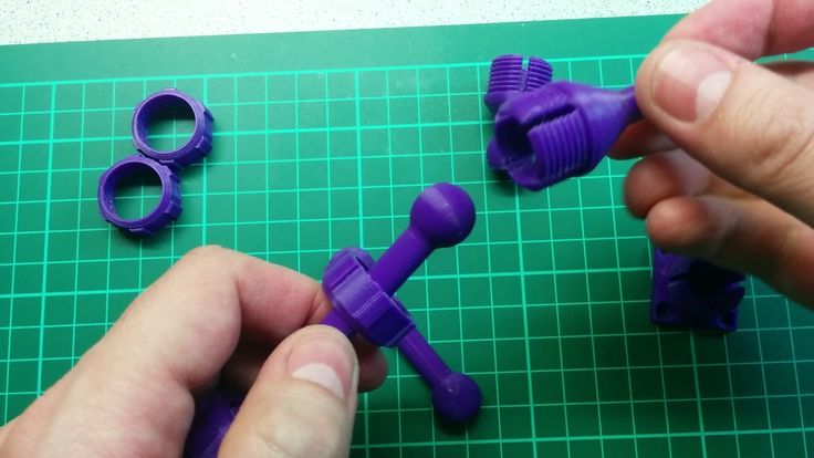
Ball Joints
- Geodesic Dome Joints
Hinges - Snap fit pivots - A good way to print a hinged pivot point. One component uses a protruding annular ball joint. The protrusion is split in half. When the component is being inserted, this gap allows the two halves to deflect and squeeze together. Once the piece is through the hole, pressure is released and the ball expands again to hold the piece in place.
http://www.thingiverse.com/thing:59332
http://www.caddedge.com/stratasys/3d-printing-blog/3d-printing-living-hinge-protoytpes
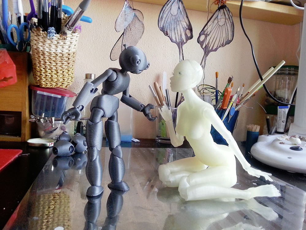
Kinematics by n-e-r-v-o-u-s http://www.thingiverse.com/thing:195497
1. Experiment with clearance sizes
Usually when fitting two parts together and printing on a desktop FDM printer, the male and female parts of the joint must have a certain clearance between to account for material tolerance.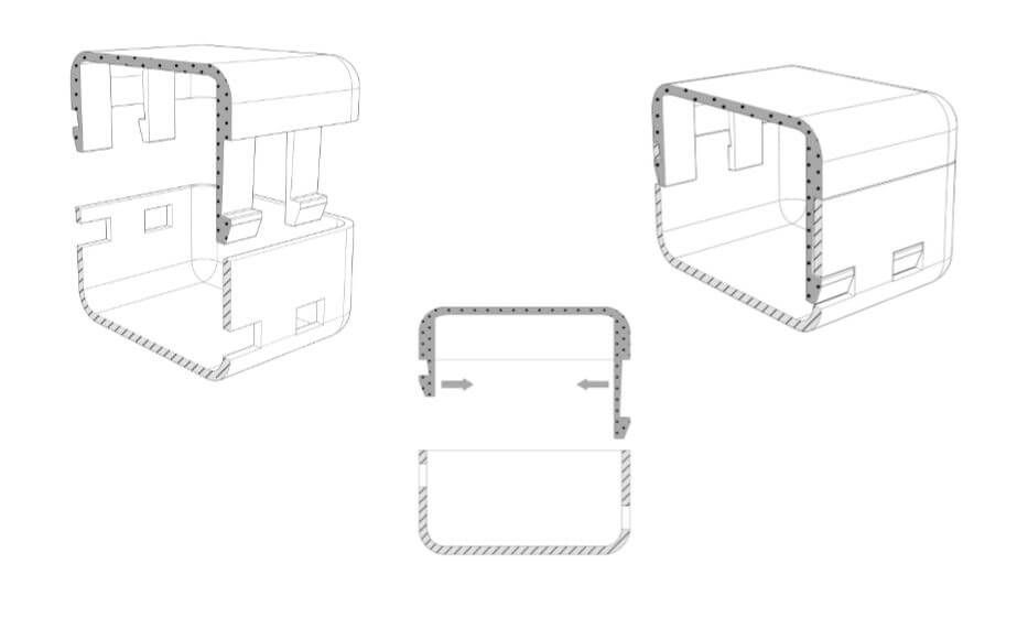 This clearance can vary anywhere from 0.1mm – 0.3mm depending on the printer resolution, material, speed, and more.
2. Test early and often
It’s good to test your connections to find the right tolerance. To avoid wasting time and material, print only the parts you are trying to test instead of the entire model.
3. Building up snaps in the Z-layer has the least amount of strength
Try to avoid printing your snaps in the Z direction (built up from the print bed vertically), they are much weaker than parts printed in the x/y direction.
4. Be careful with scaling
It is always best to model your parts at the right scale. But when you do need to scale a model with connecting parts, it will require you to readjust your tolerances.
Self Threading Screws
This is a great technique for a quick and dirty prototype. Using self tapping screws is quick, cheap and requires minimal design efforts.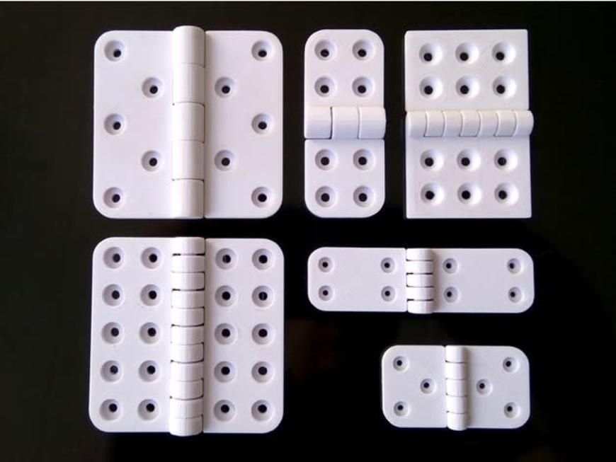
Custom Designed Threads in Your 3D Model
If you are using something with large threads, it is best to design them since trying to self tap would require a huge effort. This is only advised for large components (when printing on desktop FDM printers) – the resolution is not adequate for small machined components.
Captive Nut
A great technique for fastening is designing an inset in your model to hold a hex nut. This is great when you want to use machined bolts. It’s important to use your calipers to get exact dimensions and give enough tolerance for fitting your hex nut.
Using high heat to melt metal threaded hardware into your 3D print. The inside of this is nicely threaded for precise machined screws while the outside is roughed with gripping pattern. When it’s melted into the plastic, it will grip nicely and fit snugly when the plastic cools down around it.
How to:
- Get a crappy soldering iron (not one of nice working ones from the BTU lab)
- Heat your iron to low and preheat the threaded insert.
 This should only take a few seconds.
 - Align and place the insert on your model (use some tweezers)
- Use the tip of the iron and carefully push the insert into the plastic using little pressure. Once the insert is aligned flat with the top surface of the plastic, remove your iron.
Pro tip: practice on a test print first!!!
New 3D printing technology will put hundreds of millions of people on their feet
You are here
Home
A team of Swedish researchers has developed a new 3D printing technology that can grow cartilage tissue for joints using stem cell 3D bioprinting.
Today, millions, maybe even billions of people around the world suffer from joint diseases, most of which lead, ultimately, to loss of mobility, often people become disabled.
The main reason for this is the failure of the cartilage tissue of the joints, it stops working correctly or is destroyed, the limbs stop bending, or this causes significant discomfort and pain.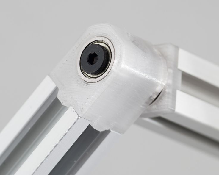
Joint cartilage
Cartilage is an amazing connective material, it is very resilient and dense, yet incredibly elastic. As a rule, there are no vessels and nerves inside the cartilage. Cartilage is formed around special cartilage cells called chondrites.
Modern medicine offers several options for restoring the cartilage tissue of the joints, in addition to conservative treatment with the use of injections and ointments, there is an operational solution to the problem when the joint is replaced with a steel prosthesis. In recent years, doctors have come up with another method, when stem cells are injected into the joint, which, when they enter a specific area, turn into the type of tissue that surrounds them.
Cartilage tissue
Unfortunately, this does not always work, often the mesenchymal stem cells that are used for such injections turn not into cartilage, but into bone tissue, which negates all the efforts of doctors.
Researchers at Restore, a Swedish company, have developed a biomedical 3D printing method to create the desired cartilage using 3D printing.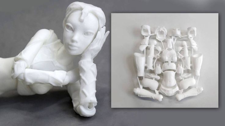
Medical 3D printer
The procedure works as follows. The affected joint is subjected to a 3D scan using magnetic resonance imaging, computed tomography and microcomputed tomography. As a result of these studies, a detailed three-dimensional model of the affected joint is obtained.
Next, bio-engineers, together with doctors, create a three-dimensional model of cartilage in a special program, which is required to replenish the missing cartilage tissue in the joint. Next, doctors receive stem cells from the patient, from which they create bio-ink for a 3D printer. The 3D printer first prints a special matrix, and then adds stem cells to the matrix along with the patient's chondrites, resulting in cartilage of the desired size, shape with 100% genetic match.
This cartilage is then implanted into the diseased joint during an operation. As a result, the patient receives cartilage created from his cells with a 100% survival rate and a minimum postoperative period.
3D printing of cartilage
Unfortunately, 3D printing technology for the restoration of cartilage tissue of the joints was only tested in laboratory conditions and clinical trials are still far away, and nevertheless, the new technology gives hope for recovery for many people
Source
Other materials:
- Plant "steaks" started to be printed on a 3D printer in Spain
- Scientists have proposed a new process for creating a gel for 3D printing using heat
- TUSUR developers will bring a new low-cost 3D printer to the market
- The company "3D Service" presented at the exhibition equipment designed for scanning objects and 3D printing of plastic products
- Map for Russia-3D
Attention!
We accept news, articles or press releases
with links and images. [email protected]
3D printed joints will help patients start a new life
Archive
Subscribe to the author
Subscribe
Don't want
1
We are already starting to get used to the daily advances in the field of 3D printing. Each new discovery guarantees even more amazing discoveries in the very near future. The media is literally seething with news about the deeds of scientists and doctors, the commission of which used to take decades.
Model (left) and printed joint (right)
One of the latest advances in medicine that would not have been possible without 3D printing is related to joint replacement. Today, there are very few ways to manage joint pain, with joint replacement surgery being considered a last resort. All over the world, people suffer from manifestations of arthritis and joint pain.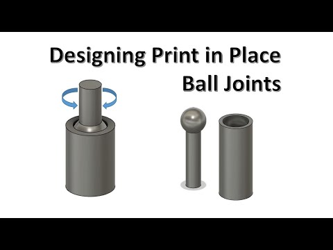 It is becoming increasingly clear that this issue needs special attention.
Joint 3D Printer
Artificial joints are usually made from plastics and metals, materials that the human body considers foreign. In addition, these materials are destroyed 10-20 years after the operation, and the joint again loses its functionality. In other words, the artificial joints that are currently being installed cannot be considered a reliable and long-term solution.
Seeking relief from the acute pain that plagues so many people, physicians Rita Kandel, Mark Greenpas, and Endras Nagy of the Samuel Lunenfeld Research Institute at Mount Sinai Medical Complex teamed up with bioengineers, biologists, and surgeons to explore the possibilities of using a patient's own tissue for creating new bones. As interest grew, Dr. Kandel began working with Drs. Pilliar and Dr. Toysercani of the University of Toronto and Waterloo to see if 3D printing could become a tool for creating joints. Here is how Dr. Kanel describes the essence of this interdisciplinary collaboration:
“First, Dr. Toisercani prints a biodegradable joint. Then we take the patient's stem cells and build up real tissue (cartilage, etc.) on this joint. The damaged joint is replaced with a joint made entirely of the patient's tissues. It's just incredible."
Dr. Rita Kandel of Mount Sinai Medical Complex
The 3D printing process begins with an x-ray of a patient's injured joint. The data obtained is converted into a three-dimensional computer model, which is immediately sent for printing. A 3D printer grows an exact copy of the joint from a special porous material. This material promotes cell growth and is easily overgrown with cartilage tissue. Gradually, the bone takes shape, and the material is destroyed. As a result, only the bone remains, which is no different from the original. Here is how Dr. Kandel describes the process and its benefits:
“A joint is a highly complex, shaped structure, all of which work together to ensure painless movement of the knees and elbows.![]()
Learn more