How to slice 3d model for printing
Slicing - Getting Started with 3D-Printing
You've read a lot on this page - you've come really far. But unfortunately the most overlooked and perhaps the most difficult setting - speed - was saved for last. So take a break if you need - get up and stretch - and let's dive back in when you're ready.
If speed is a measure of distance during a unit of time, we typically measure speed in millimeters per second.
Speed is relative to many things: the material, the temperature, the infill pattern, etc. All those settings 'pass through' the speed setting - put another way the speed setting is how all those other settings get interpreted, as in at what speed, measured in millimeters per second.
A millimeter may be relatively small to humans, but that doesn't mean we should set the machine to travel as fast as possible. For instance most 3D-printers may be capable of extruding plastic at say 200mm/s, but that doesn't mean it's a good idea. (Spoiler: it isn't.)
Similar to how there is no universal PLA temperature setting, there is no perfect speed setting. You will have to experiment, and learn.
And this is where it gets tricky! With infill you likely only have one setting for density and one setting for pattern. With layer height you generally only have one setting to worry about. With temperature you have usually at most two settings, and usually only one. But with speed, you may have two, three, or even five or seven settings. This is why speed is such a tricky issue.
Simple software typically has:
- the speed of the print head when it is not extruding plastic.
- the speed of printing rafts, skirts, or brims. (optional)
- the speed of printing the infill pattern.
- the speed of printing the first layer.
- the speed of printing the shells.
That's the simple version! More complex software will typically allow you to also set the speed for:
- areas known as 'bridges' (intermediate subject matter).

- the speed of printing Supports (as a setting separate from the perimeter print speed).
- the speed of printing the very top of the print - the roof.
- the speed of various types of perimeters.
- and even more!
You can see 'speed' has many applications, and it will always depend on what you're printing.
That's why there is no universal 'just use these numbers and you'll be fine' setting, and also why it's vital to look at the settings used by others to determine a baseline approach for your own prints.
OK we intentionally set up speed to sound scarier than it really is. Some software may 'auto adjust' the speed settings in real-time, but if you want control over your print (or if the software doesn't have a 'smart' 'auto' feature) you'll have to learn the various speed settings.
All that said, let's go over some numbers now!
The three main speed settings to keep in mind are:
- the speed when not printing (when the print head is simply moving around, getting into position - this is broadly referred to as travel speed),
- the speed of printing the shell / perimeter (the outermost shell may be referred to as "outline,"¹ and
- the speed of printing the infill.
For travel speed generally somewhere between 90mm/s to 120mm/s is good - even up to 180mm/s can be fine. Remember this is when the printer is not extruding. For example say you have two objects on the build plate, and they're spaced apart. The travel speed is absolute and will apply to the distance between the two objects at the same layer - in this image this is layer # 1071:
When the printer completes the layer on the object on the left, it will then speed up to the travel speed when it is not dispensing plastic and migrate to the object on the right (and vice versa). It will then adjust to the speed of the perimeter setting.
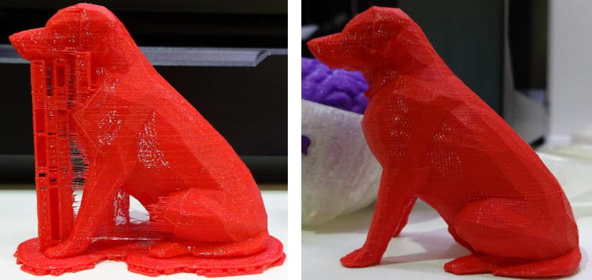
For perimeter speed this is the speed you probably want to pay the most attention to. There really is no 'perfect' setting. It all comes down to the geometry of your print. We're referring to all those polygons of the .STL. You can imagine you probably want to have different shell speed settings for these two example files:
The file on the left has a lot of little squiggles, arcs, and curves; the file on the right is entirely straight lines (and right angles).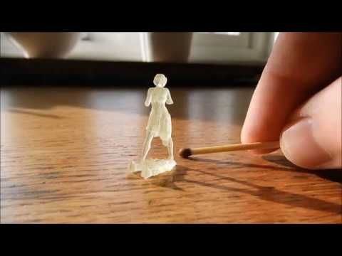 Mechanically there's a lot less 'work' the machine has to do in the print on the right than the print on the left, even though the print on the right effectively travels farther, and therefore dispenses with more material.
Of course these are just sample single layers from prints that have hundreds if not thousands of layers. You don't change the speed setting layer by layer - you set a single setting for all layers. How to choose the correct speed for all the layers? There is no answer other than trial and error.
If you are only afforded a single perimeter setting something in the range of 25mm/s would be good for the file type on the left (with lots of 'small perimeters' and degree changes) whereas something around 50mm/s should be fine for the file type on the right. (Sadly, some programs are defaulted to 90mm/s (or more) when you open the slicer software, which leads to many beginner getting frustrated with failed prints early on in their 3D-printing adventures. )
)
¹ The reason for having an "outline" shell that may (or may not) be treated at a different speed than the interior shells, is because the 'outline' is the one you see - it is the most exterior shell. Because the exterior shell is the one you actually see, you may want to give it a different speed setting - typically a slower setting, so as to give it a 'finer' treating.
The final speed setting to really be aware of is the infill speed. Similar to the perimeter speed mentioned above this setting really depends on the two properties associated with infill: density, and pattern. You can imagine a pattern like grid or rectilinear will mostly be straight lines, and could probably be set to a marginally faster speed than stars, honeycomb, or 'specialty' infill patterns. Somewhere between 40-60mm/s is broadly supported, and you may even be able to go higher if your hollow interior is very large and your pattern is very simple.
In the following example of an architectural print - a tower - we see infill density at 15% and 7% (slightly under half of 15%) using a 'diamond' pattern:
Because the print is scaled so large, filling in all that empty space even with 15% density seems like overkill. 7% looks like it should provide plenty of support. Furthermore the 15% density requires nearly 90g of material and 6 hours and 44 minutes of time; the 7% density only requires 65g of material and 5 hours and 31 minutes of time - more than an entire hour shaved from the print time!
The underlying point here is infill density and pattern are also relative to scale. If the print was smaller all the numbers would be closer together; but as the print scales up in size, all the numbers exponentially increase!
You may be able to trim the 15% density print time by speeding up the infill print speed, but again be cautious of the infill pattern you use.
How to Slice STL Files in Cura
Slicing STL files can be a daunting task, but luckily there are many software programs out there that can make the process much easier. Ultimaker Cura is one such program that is specifically designed for slicing STL files.
But, do you know why a lot of 3D printing enthusiasts choose to slice STL files in Cura? And how to Slice STL Files in Cura?
Let’s get started!
Slice STL files mean converting STL files to G-Code files to let the 3D printer understand. Ultimaker Cura is one of the best STL to G-code converters. To be continued, we'll show you how to slice STL files in Cura so that you can get started printing your 3D models right away.
Step 1: Download and install Cura. You can find the latest version of Cura here. Once you have Cura installed, launch the program and add your printer, in my situation, added Creality Ender-3 Pro. And click on the "Next" button to continue.
Step 2: Now, in the top left corner, go to File > Open File(s) > Select Model File.
Step 3: After uploading the file, you will want to remain within the recommended settings as provided within Cura. Or you can customize your print settings. When you're happy with your slicing settings, click on the "Slice" button.
Step 4: When the slicing process is complete, you can preview and save the slice file to the desk. Now you're ready to start printing!
Pros and cons of slicing an STL file in Cura?
Utilizing Cura to slice an STL file is a great tool for 3D printing enthusiasts to leverage in preparing their models for printing.
Pros
- By slicing the 3D model into many layers, Cura produces a crisp and clean output with far greater resolution than would be possible by 3D printing by itself.
- Furthermore, users can also modify the settings in relation to material composition, layer height, and more which are essential for improving print quality and precision.
- Another great advantage of using Cura is that it allows users to view their sliced model before exporting the G-code required for producing the actual 3D object through software like Repetier Host or Slic3r Prusa Edition. This not only saves time and money but also promotes user satisfaction since they can ensure that their model remains true to its intended design.
Cons
Despite its many benefits, Cura has some notable drawbacks.
- It can be difficult to learn and understand, with a steep learning curve for new users.
- Additionally, the 3D prints it produces may also not always be known to match up perfectly with the design file or even the first layer of filament down in certain cases.

- Furthermore, Cura is unable to print multiple objects at once with one click of a button, meaning long waits and additional steps that have to be taken in order to print multiple objects.
- Lastly, it is limited in terms so STL files only and cannot unpack zip archives containing the desired 3D model files.
The best alternative way to slice a 3D model for printing
Now you learned more details about Cura for slicing STL files, including the pros and cons. If you are looking for the best alternative to slice STL files, it is not controversial to say that Creality Print is your best choice.
Creality Print makes it fast and easy to create 3D prints from STL files. The software can be used with any model, giving users maximum design freedom. Follow the below steps on how to slice STL files using Creality Print:
Step 1. Download and install Creality Print on your desktop (Windows, Mac, or Linux system).
| System | Download link |
| Windows | Creality_Print-v3.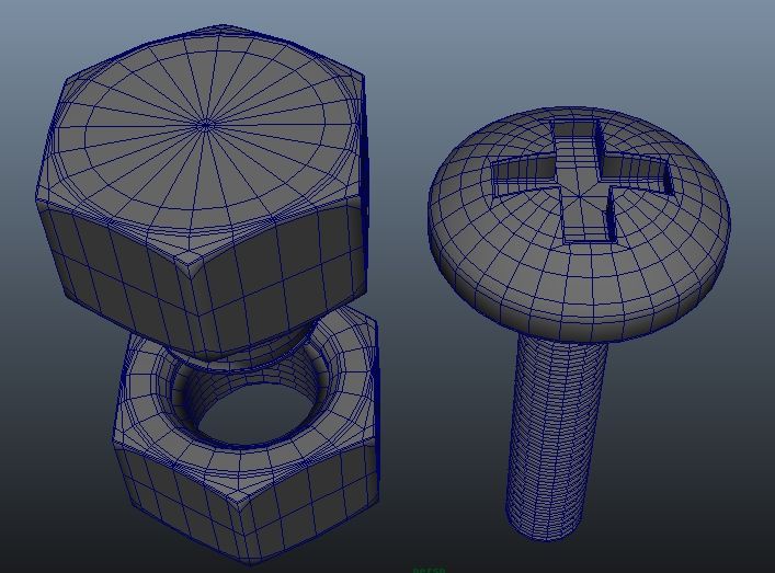 12.2.3188-win64-Release.exe 12.2.3188-win64-Release.exe |
| Mac | Creality_Print-v3.11.1.0-macx-Release.dmg |
| Linux | Creality_Print-v3.11.1-Ubutu-x86_64-Release.AppImage |
Step 2. If you are a new Creality Print user, you need to add your printer model to start (Supports Creality Printers only). This will guarantee your slicing file is appropriate to print.
Step 3. Now, you can upload your STL files to the software by clicking the Import Model button in the right tab. If you are a Creality Cloud user, you can sign in to your account, and find the STL files to sync to Creality Print. You also can adjust print settings in this step.
Step 4. Next, click on the Start Slice button to convert your STL to G-code.
Step 5. Export your converted STL file in G-code to your desktop.
Creality Print offers speedy slicing times, precise detail, and intuitive controls which make it one of the most reliable 3D slicers on the market today.
It also has a wide variety of settings available so you can tweak your models to perfection.
Furthermore, Creality Print's filament compatibility allows you to use multiple materials ranging from plant-based biodegradables to traditional ABS and PLA plastics. With seamless software integration and nearly unlimited design possibilities, Creality Print provides an outstanding 3D printing experience that's sure to satisfy even the most demanding users.
Conclusion
Slicing STL files doesn't have to be difficult. With Cura, you can quickly and easily slice your STL files so that you can get started printing your 3D models right away. However, as we mentioned before, Cura has some notable drawbacks.
So here we recommend the best alternative for Cura: Creality Print, it can batch slice, and even offers free models to slice directly.
How to cut a 3D model into parts?
01/16/2017 in 3D Modeling, Instructions
A very common situation - a part is not included in the maximum dimensions of the 3D printing area, no matter how you twist it there.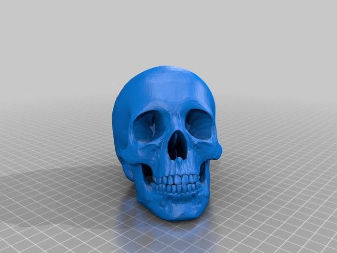 There is a solution! We cut the part into several parts, and after printing, you can glue, solder, sew, weld, or simply dock. How to cut a 3D model into its constituent elements is described in this article. At the same time, it must be remembered that with this 3D printing method, it is necessary to take into account the accuracy of matching the components. More details about accuracy can be found in the article: ACTUAL PRODUCT SIZE AFTER 3D PRINTING.
The following methods have been described based on the capabilities of the NetFabb program. This does not mean that you can cut the model only in NetFabb. Similar capabilities exist in a variety of 3D modeling software. At the same time, the essence and approach remain the same.
Contents:
- Explode the object into components along the plane.
- Break the object into pieces with slots or latches.
- Break an object into its component parts with curly cuts.
- Video instruction.
1. Split into components along the plane.
To split a part into several objects, use the NetFabb program. More information about the program and its features can be found here.
After opening the model in the program, look for the “cuts” window. We start moving the sliders. As you can see, a strip appeared on our model. The so-called cutting line. Click "execute cut".
The cutting plane appears. Here we can more accurately adjust the cut line in terms of dimensions. We press "cut".
As you can see, our part is cut into two parts. Each part can be saved as a separate file and printed separately.
Let's look at another situation where we need additional clamps or guides for correct positioning after breaking into components.
2. Break the object into pieces with slots or snaps.
Take Misha the Bear and mark the cut line and press the “Cuts” button.
But now before the “cut” operation, we click on the “pin settings” button.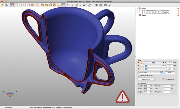
You should be presented with a window where you will need to select what kind of alignment guides you require.
Cylindrical taper groove:
Or the so-called latch:
I chose the latch and determined all the parameters that I required. Please note that you can select the size, depth, overhang and other parameters for connecting structures.
As you can see, our bear has additional fixators after breaking.
This path will not only help you correctly position the two parts relative to each other, but also fix one part to the other!
3. Break the object into its components with curved cuts.
This section describes how to cut a 3D model with shape planes. Please note that you can only break an object into its component parts with curly cuts if the model meets the requirements for 3D printing. If errors occur in the model while cutting, correct the model immediately after each cut. Before each subsequent cut, check the model for errors and correct them using the appropriate tools in Netfabb.
To be able to cut a detail in the free space of the 3D model, you need to find the “Free Cut” button and click on it. After that, it is necessary to mark the points sequentially in such a way as to describe the segment to be separated.
See below how it looks in perspective.
After the “Cut” command, you will get a separate segment and you can save it as a separate file.
So even if the 3D model doesn't fit in the 3D printable area, you can split it into many segments along natural fold lines. And after 3D printing, the segments will be beautifully joined to each other.
Please note that the cut lines can be as complex as you like.
And there can be as many cuts as you like.
Another example of such an iteration.
This approach will allow you to get even more quality in 3D printing.
4. Video Tutorial
Tags: 3D Modeling
Architectural 3D Printing Modeling Strategy Guide and Software Use
At a Glance
3D printing brings enormous benefits to the conventional architectural workflow. You can print complex designs without the need for skilled craftsmen, and quickly modify these designs without too much difficulty. Stereolithographic (SLA) 3D printing delivers incredibly high surface quality and detail, making it suitable for architectural applications. This paper explores modeling strategies and software workflows that enable architects and designers to easily integrate 3D printing into existing design methodology, create best practices based on internal testing by Formlabs and architecture firms, successfully using Form 2 to create 9 models0003
WHAT YOU WILL LEARN:
Strategies for designing 3D printed architectural models
Tips for improving your workflow Pre-print processing software
- Building information model (Revit, ArchiCAD)
- Surface modeling (Rhino, SketchUp)
Effective post-processing techniques
- Compound
- Finishing
Introduction
The 3D printing market today offers affordable options in both price and scale.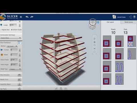 While professional-grade technology used to be costly, desktop stereolithography 3D printers allow architects, designers, and model makers to offer high-quality, in-house fabricated parts.
Most models cost less than $10 per part.
3D printing opens the door to creating complex designs with less effort and fewer materials, but the successful transition from CAD model to printable file is based on a basic understanding of design for 3D printing. This document will help you understand how standard modeling constraints relate to preparing a file for 3D printing, as well as approaches and decision making for intelligent modeling - from scale selection to design and assembly for post-processing.
To integrate these strategies into existing workflows, this booklet explores ways to approach modeling strategies tactically by examining three of the most common software ecosystems: allows you to include small details even on the smallest models. This example of a small city model has a scale of 1/32″ = 1’ and is completely printed on a Form 2 3D printer. Many small details and parts of this design will take significantly longer if cut and assembled by hand. Model from LaneyLA Inc.
This auditorium section was 3D printed as one piece on a black resin Form 2. Model from DLR Group.
Modeling strategy
Architectural models are usually assembled using various materials and components. 3D printers help combine these components into as few separate parts as possible, but assembly manipulation is still necessary for two reasons:
- Build Volume Limitations : High build volume printers are either expensive or compromise on surface quality. Form 2 build volume is 57 x 57 x 69 inches (145 x 145 x 175 mm)
- Need to show interior details or materiality : Some models require components to be separated to show more design information.
DESIGN FOR ASSEMBLY
All 3D models require preparation before they can be sent to the 3D printer. In the case of architectural models for the Form 2, this often involves splitting the model into smaller parts to fit the scope of the Form 2 build. The parts can then be easily joined together by chemical adhesive or mechanical assembly; high precision printing ensures that the parts fit together.
When choosing dimensions for parts to be separated, consider the final orientation of the model. Most architectural prints need to be oriented at a 45 degree angle due to floor slabs being considered large horizontal projections. Dividing the model into long, thin parts helps maximize the diagonal length of the build volume while achieving perfect orientation
Strategy overview
There are several strategies for assembling 3D printed models. Your strategy will depend on what you hope to represent with the design, as well as the scale and geometry of the model. Consider the following parameters:
- Need to show internal or external parts
- Easy Split (You want to split the model by the least complex part of the model)
It is necessary to show a certain part of the program: typology, structure, floor layout
| Seam separation | Separation by component |
| Section model | Separation by program |
| Straight cut | Separation by structure |
| Aligners |
Seam splitting
STRAIGHT CUT
The easiest way to split a model is with a straight cut. This is a simple command to execute in most CAD software. The bridge model is divided lengthwise using straight cuts into four parts, one of which is shown above. Each support post is inserted into
mating hole that does not require glue. Regardless of which method you choose, if you have a large number of parts (more than 10), it can be helpful to add a unique identifier for each part to help solve the puzzle during assembly.
Pros:
- Least heavy use of CAD
- Greater tolerance for prints that warp or have a higher degree of dimensional change
Cons:
- Assembly requires manually leveling each piece and fixing it in place until the adhesive is fully bonded
Try to print all components in the same orientation so that the layer lines and subsequent dimensional inaccuracies follow the same pattern.
ALIGNMENT TOOLS
Another approach is to add features to the design that will allow the prints to align. When adding mate fixtures, try to subdivide the model in areas with the least complex geometry. Use the CAD tool of your choice to split your model and add basic alignment fixtures such as slots, pins, grooves, recesses and flanges, or more complex fixtures such as dovetails and cuts that follow existing model curves. In addition, it is important to create a design with ~0.25 mm tolerance between mating parts to prevent additional sanding at the post-printing stage.
Pros:
- Easy alignment Parts that are not accurate
- Easy to assemble (mating parts help create a large surface area for adhesion)
- High precision SLA allows tight fit with high tolerance and can be used without adhesive
Cons:
- Parts that are not true to size will not fit well. High fine details are often less accurate.
SECTION MODEL
The separation of the model with a seam has the additional task of showing the section model for structures with irresistible interior details.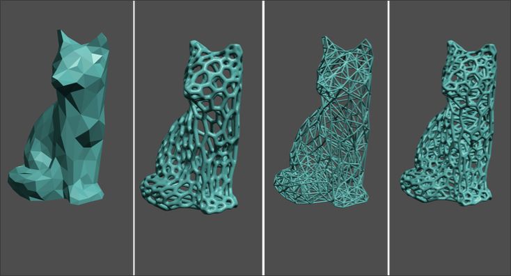 Initially, the model can be presented as a whole to the client, and then disassembled to reveal interior details as desired. These LaneyLA examples show how the same model conveys different types of information based on open and closed configurations
This model from LaneyLA was printed on a White Resin Form 2.
Using devices for combining: Methods component
SOFTWARE SPLIT
By breaking down a building with software, you can represent the building as a set of parts, providing a clear understanding of all design components without a plan and section drawings. You can print each floor slab separately and then assemble using mates, or just print one component of the entire building separately from the rest. A good example is the model from Stanley Sitetowitz | Natoma Architects Inc (SSNAI), who used the Form 2 to model the residential complex.
Model by Stanley Sitetowitz | Natoma Architects Inc.
Since each body block followed the same pattern, it makes sense to simply print one detachable block that will allow the customer to understand the typology of the typical device
to print as a single block or separate along the seam.
This method usually works for models that do not have straight lines, such as typical building blocks, but complex structures, such as detailed building sections, bridges, pavilions, or airports.
First, break these models down into components that can be 3D printed with minimal supports. This saves post-processing time (removing supports for delicate models can be tedious) and reduces material costs and print times.
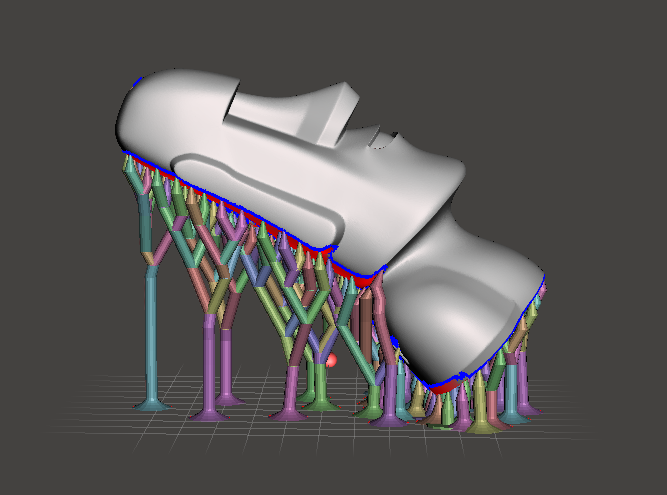
This bridge example demonstrates multiple partitioning methods. First, the model is divided into several parts (Figure a). While they fit the
Form 2 build platform, they require painstaking removal of supports around more delicate areas such as cables and railings.
To solve this problem, each part is broken down into three sub-components: base plate and railing, vertical tensile cables, and solar panels on top (figure b). They can be printed with significantly fewer supports, making it easier to finish,
Once completed, the components simply need to be assembled using the alignment functions that were included in the design phase. Smaller parts are also easier to place on a single build platform, with the entire bridge being printed from five 100ml parts.
Model from T.Y. Lin Architects
This playground model was created using laser-cut fiberboard. The primary building was 3D printed in clear and white resin. Model by Schwarz Silver Architects
Materials
Materials play an important role in conveying the basic design concept. It is not always necessary to model the exact color and texture of a material, but it can help separate different materials. Dividing a model into its components allows for the display of materiality, as parts can be printed in different materials or individually dyed in different colors.
The transparent façade is illuminated from within, simulating the visual conditions of this site at night.
Formlabs Matte Resins
Black, White and Gray out of the printer have a smooth, opaque finish and provide an excellent neutral palette for architectural models. Gray and white resins are also easy to process and can be finished with just a few coats of paint, as discussed further in the finishing section of this document.
Formlabs Clear Resin is excellent for printing features that mimic translucent materials. If your model requires more transparency, you can simply dip the printed part in clear resin and let it dry evenly, as described in this article on making clear resin parts. You can also spray any clear coats on the model to increase the transparency and glossiness of the surface.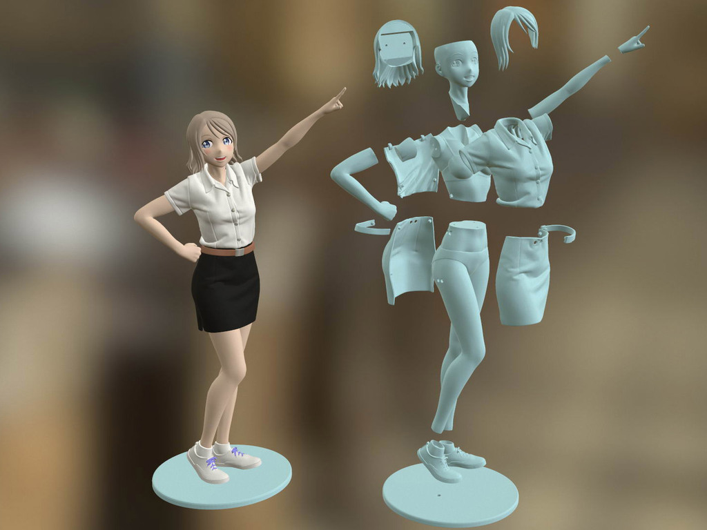
3D PRINTING AND TRADITIONAL MATERIALS
This model uses the Form 2 to print very fine details such as the cornice, clock and railing. Model by Miles Burke Architectural Models Inc.
Instead of 3D printing an entire building, sometimes it's better to print just the complex components. Complex facades, slings and cornice details are excellent candidates for SLA 3D printing. Flat walls, floor slabs and topography can be laser cut or even hand-drawn
This complex façade is parametrically designed based on solar trajectory analysis and would be incredibly difficult to fabricate in any other way at this scale.
Software Workflow
Good printing comes from a well-designed 3D model. This section will cover modeling best practices and workflows for printing in some of the most common CAD environments:
Revit, SketchUp and Rhino
CAD software is typically the bottleneck in the transition from drawing to 3D printed model
General workflows
IMZ workflow
901 PreForm
While BIM (Building Information Model) software is popular with architecture firms, it is not always used for direct 3D printing models. There are some high level steps that you can take
take to create a 3D printed model from these programs. This workflow is widely applied to Autodesk Revit or Graphisoft ArchiCAD software, both of which are IMZ parametric modeling programs.
PREPARE THE FILE
STEP 1: Prepare a separate offline file
STEP 2: Manage components: remove ducts, double glazing, HVAC units and internal parts that will not be visible in the model
STEP 3: Select all components to be sealed (eg doors, windows, walls, slabs). The parametric nature of the model allows you to simultaneously compact the dimensions of several objects.
EXPORT FILE
Select the scale at which you want to export the file. Select the export options depending on the needs of your model:
EXPORT AS STL
Exporting the file as a mesh is very difficult to manipulate, so this is only useful if you don't want to edit any geometry after this step.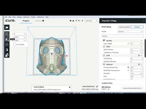 You can then use your software to correct the mesh of your choice, as well as subdivide the mesh along the main Cartesian planes.
EXPORT AS 3D DWG
Export as surfaces allows you to easily manage and edit geometry in Rhino or SketchUp. This step is recommended for those who want to split the model programmatically or by component, or split by a seam that is not on the normal Cartesian plane. You can then export the STL file from Rhino or SketchUp using the plug-in
EXPORT USING ARCHICAD
Perform a geometry transformation to Morphs and a "consistency check" before exporting the model as STL. When printing in parts, use tool
"Divide" to cut the model for multiple print platforms if needed. This operation basically creates printable files, but a quick check in mesh repair/analysis software never hurts.
USING STL REVIT EXPORTER
This method automatically removes smaller details such as doorknobs and railings. However, it is not reliable and still often requires some post-processing in other CAD environments before being sent to print.
Surface Modeling workflow
AutoCAD → Rhino/SketchUp → Model Diagnostics → PreForm
This workflow is often an easier approach and starts with 2D drawings solely for the purpose of 3D printing
FILE PREPARATION STEP 1: Hide unwanted layers
STEP 2: Identify and remove unnecessary elements such as furniture, trees, etc.
EXPORT FILE
STEP 1: Export the simplified drawing from Rhino as DWG
STEP 2: Import into Rhino
STEP 4: Start extruding and trimming until you get the outer shell.
STEP 5: Export as STL STEP 6: Mesh Analysis/Correction STEP 7: Import to PreForm
Note: If the model will be printed in several parts, split it before exporting as STL
THIN WITH RHINO
Instead of parametrically controlling the thickness of components directly in the BIM file, you can also use the BoxEdit component in Rhino.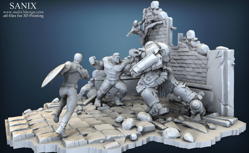
This allows you to simultaneously scale a number of elements in relation to their center lines. BoxEdit is ideal for models that need to be scaled parallel to three Cartesian axes. Non-uniform scaling is a little trickier.
For non-rectilinear geometries, we suggest converting the part to a mesh and then using the Weaverbird thicken command, which simply offsets any non-standard mesh geometry outward by a given distance. Alternatively, it is possible to "split" complex parts into surfaces and then offset them instead of importing volumes from Revit.
SELECTING SMALL GEOMETRIES WITH RHINO
Another valuable feature of Rhino is the SelSmall command, which allows you to select all elements in the Stage that are smaller than a custom bounding box. You can then select those objects and use
BoxEdit for individual scaling or just remove them. This is useful when you are dealing with a file that does not have a well organized layer system.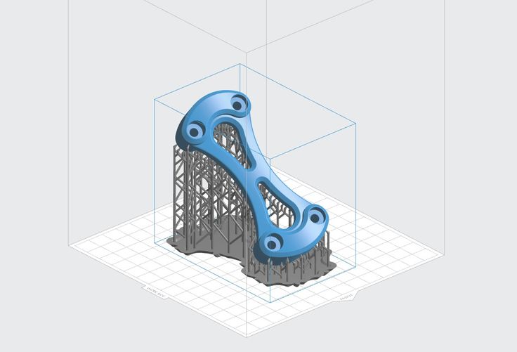
Although performing a logical connection on all geometries is ideal, often the problem can be solved with simple overlapping geometries. PreForm will interpret them as one closed geometry in most cases, but be sure to check printability with the "slicer" tool in the right pane in PreForm
. CONTINUOUS / LOGICAL JOINT GEOMETRY
Note : PreForm is Formlabs free software that prepares your 3D model for printing in Form 2. Once the part is set up, you can save it as a FORM file for future use in preform.
COMPUTATION WORKFLOW
Although a less common workflow, computational design is slowly being introduced into mainstream architectural workflows. Software such as Grasshopper and Dynamo are used to create parametrically generated geometries that are often so complex that they can only be created with 3D printing.
Since geometries are already easy to manipulate, it's usually best to create a separate component that allows you to easily control the basic dimensions of all thin objects. In this case, it's a simple matter of trial and error; running the exported geometries with a print test (PreForm,
MeshMixer) and resizing until you arrive at a printable file.
Model Diagnosis
All workflows described below share a potential "generic diagnosis". This is an optional (but often necessary) step to ensure that the model is fully printable. Free programs such as Autodesk's MeshMixer and Netfabb are tools that allow you to repair, smooth, cavity, and split 3D print files.
MESH FIX
Formlabs PreForm software uses Netfabb's built-in mesh fix, so NetFabb and MeshMixer must be used for custom fixes or to preview problem spots in print. Materialize Magics is a great proprietary tool that covers the entire preprint workflow for a wide variety of printer types. The mesh patching software part is most important to the Form 2 print workflow and can save you a decent amount of preparation time. Netfabb has a beautiful built-in model cutter that allows you to effectively split and restore large files along any Cartesian plane.
SPLITTING THE MODEL
It is also possible to split the model in NetFabb, which splits and fixes the split parts into printable volumes. In Rhino, you will need to close open volumes. Be sure to leave a tolerance of ~0.25mm between adjacent parts, this will allow them to be inserted without friction.
See our technical data sheet for details on tolerances.
PREFORM SLICER
Architectural models are highly detailed and it is often difficult to isolate each print issue. A combination of the above practices and mesh repair software is usually used for almost all problems, but it's always wise to use the PreForm Slicer tool to make sure there are no thin unsupported areas and enclosed volumes (such as rooms with no doors, elevator shafts, and parking spaces) .
“Building and architecture structures are not meant to be 3D printed, they are meant to be built. This creates problems of scale and complex geometry. By combining Netfabb's powerful mesh repair tools with the precision of the Form 2, you can prototype and visualize designs faster and in more detail, benefiting more for your business and speeding up your project's design review process.”
Matt Lemay. Lead Enterprise Solutions Provider, Autodesk Customer Service
Post-Processing
Joining
The modeling strategy section of this booklet covers some ways of splitting and aligning parts together, but glue is always needed for a secure connection. Architectural parts are bonded in two main ways:
CYANOACRYLATE
Cyanoacrylate (CA or Super Glue) creates a fast, reasonably strong bond ideal for small to medium sized parts. CA does not bond dirty surfaces well, so be sure to thoroughly clean the part before applying adhesive to the surface of the model.
POLYMER
For smaller prints, you can use liquid resin as a binder. Dispense a small amount of resin into the tray from a bottle or cartridge, use a dropper or syringe to lift it up, and place it on the surface of the part to be bonded.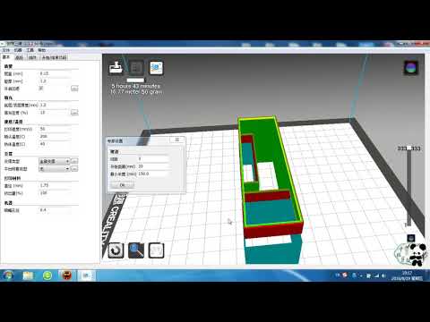
Join parts and wipe off any excess resin that may be spilling around the edges. To cure the resin and bond the parts, use a 5 mW laser pen at 405 nm and point it at the bonding area around the parts.
This method creates a chemical bond, just as if the part had been printed on your SLA 3D printer, but only applies to small bonding surfaces because a low power laser pen cannot penetrate the model deep enough to create a strong bond .
FINISHING
Parts printed on Form 2, especially matte standard resins, have a smooth surface immediately after exiting the printer. However, visible areas with supports almost always require sanding. In addition, you can prime and paint parts in any desired color.
GRINDING
Sanding will help you remove the support marks and any remaining inaccuracies from your model. Start by carefully dry sanding the surface of the part using ~150 grit sandpaper to remove large support marks and smooth out the edges of the joint. Once the surface of the part is smooth, wet sand with 320mm sandpaper to remove any remaining layer lines. Move the sandpaper randomly to avoid grain formation.
In most cases these two steps will create a fairly even finish, but you can continue to increase the grit size of the sanding paper by a factor of 2 and use wet sanding on the entire piece until the surface is the desired smoothness.
Once you have finished sanding your model, wash the model in soapy water to remove any dust or debris and dry thoroughly before proceeding to the last step.
The architectural models are very detailed and it is quite difficult to access certain areas with only sandpaper. You can use different sizes of nail files to get to problem areas of the model.
PRIMER AND PAINTING
Priming is required before parts are painted to ensure the paint adheres to the surface. Priming can also make it easier to find areas that require additional finishing. A quick spray of primer over the model makes the support marks very visible, so you can instantly identify areas that need additional sanding.