3D printing jerk settings
How to Get the Perfect Jerk & Acceleration Setting – 3D Printerly
You’ve tried countless solutions for your bad quality prints but nothing seems to be working. You’ve now stumbled upon these magical settings called the jerk and acceleration and think it might just help out. This is definitely a possibility and it has helped many people get high quality prints.
How do I get the perfect jerk & acceleration settings? Based on trial and error it’s been found that a jerk setting of 7 for the x and y-axis and an acceleration of 700 works very well for most 3D printers to solve printing issues. This is a good baseline to start from but it could take some tweaking on your 3D printer to get the settings perfect.
This is the short answer for your jerk and acceleration settings that should get you prepared. It’s a good idea to keep reading to learn some key information about these settings such as what they actually change, what problems they solve and more.
Whether you are looking for the best jerk and acceleration settings for an Ender 3 V2 or similar 3D printer, this should be a good starting point.
I wrote an article about 8 Ways to Speed Up Your 3D Prints Without Losing Quality which you can find useful for your 3D printing journey.
If you are interested in seeing some of the best tools and accessories for your 3D printers, you can find them easily by clicking here (Amazon).
What is the Acceleration Setting?
The Acceleration setting measures how fast your print head speeds up, limited by your designated 3D printer speed in your slicer settings.
The higher the setting, the quicker the print head will get to its maximum speed, the lower the setting, the slower the print head will get to its maximum speed.
A lot of times your top speeds won’t be reached when 3D printing, especially smaller objects because there is not much distance travelled to make full use of the acceleration.
It’s very similar to a car’s acceleration, where if a car can go a maximum of 100 kph, but there are a lot of turns in your journey, you’ll find it hard to get to the maximum speed.
In the Cura slicer, they state that enabling ‘Acceleration Control’ can reduce printing time at the cost of print quality. What we can hopefully do on the other side is improve our Acceleration at the benefit of increasing print quality.
Your slicer doesn’t actually have much to do with acceleration, in so far as emitting G-code to say where the print head should go and at what speed. It’s the firmware which sets limits to speed and deciding how fast to accelerate to a given speed.
Each axis on your printer can have different speeds, acceleration and jerk settings. The X and Y axis settings are generally the same; otherwise your prints can have different features dependent on part orientation.
There are limits on how high you can set acceleration, especially when printing at angles larger than 45 degrees.
For people struggling with various 3D printing issues, you might want have wanted more guidance towards getting ideal 3D printing results. I created a course that’s available to get called Filament Printing 101: Beginner’s Guide to Filament Printing that takes you through some of the best 3D printing practices early on, so you can avoid those beginner mistakes.
What is the Jerk Setting?
It’s quite a complex term and has different descriptions based on what firmware you are using. It’s basically an approximation value that specifies the minimum speed change that requires acceleration.
The Jerk setting measures the speed at which your print head moves from its still position. The higher the setting, the faster it will move off from a stable position, the lower the setting, the slower it will move off from a stable position.
It can also be known as the minimum speed your print head will slow down before initiating speed in a different direction. Think of it like a car driving straight, then slowing down before a turn.
If Jerk is high, your print head won’t slow down as much before making the directional change.
When the print head is told to change speed and direction in the G-code, if the difference in speed calculations is less than the specified Jerk value, it should happen ‘instantaneously’.
Higher Jerk values gives you:
- Reduced printing times
- Fewer blobs in your prints
- Increased vibrations from rapid changes in direction
- Smoother operation around corners and circles
Lower Jerk values gives you:
- Less mechanical stresses to your printer
- Smoother movements
- Better adhesion for your filament at direction changes
- Less noise from your printer
- Less lost steps as you may get with higher values
Akeric found that having a Jerk value of 10 gave the same printing time at 60mm/s speed as a Jerk value of 40. Only when he increased the printing speed past 60mm/s to around 90mm/s did the jerk value give real differences in printing times.
High values for Jerk settings basically mean the change of speed in each direction is too fast, which usually results in extra vibrations.
There is weight from the printer itself, as well as from the moving parts so a combination of weight and fast movement doesn’t go too well for print quality.
The negative print quality effects that you’ll see as a result of these vibrations are called ghosting or echoing. I’ve written a quick article on How to Solve Ghosting & How to Fix Banding/Ribbing which goes through similar points.
Which Problems Do Jerk & Acceleration Settings Solve?
Adjusting your acceleration and jerk settings has a whole host of issues that it solves, even things that were not known to you as an issue.
It can solve the following:
- Rough print surface
- Removing ringing from prints (curves)
- Can make your printer a lot quieter
- Eliminate the Z-wobble in prints
- Fixing the layer line skips
- Stop your printer from running too violently or shaking too much
- Many print quality issues in general
There are plenty of people who went and adjusted their acceleration and jerk settings and got some of the best print quality they’ve ever had.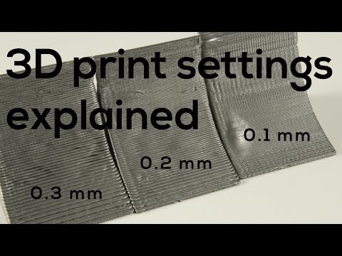 Sometimes you don’t even realize how good your print quality can be until you actually get it for the first time.
I’d definitely recommend trying this fix out and seeing if it works for you. The worst thing that can happen is it doesn’t work and you just change your settings back, but with some trial and error you should be able to reduce issues and increase print quality.
The video below by The 3D Print General goes into the effects Jerk & Acceleration settings have on print quality.
How Do I Get the Perfect Acceleration & Jerk Settings?
There are certain configurations which are tried and tested in the 3D printing world. This is great because it means you have to do very little testing to get the best settings for yourself.
You can use these settings as a baseline, isolate either acceleration or jerk, then increase or decrease it little by little until you get your desired quality.
Now for the settings.
For your Jerk setting you should try 7mm/s and see how it goes.
Jerk X & Y should be at 7. Acceleration for X, Y, Z should be set to 700.
You can go directly into your menu on your printer, select the control setting, then ‘motion’ you should see your acceleration and jerk settings.
- Vx – 7
- Vy – 7
- Vz – can be left alone
- Amax X – 700
- Amax Y – 700
- Amax Z – can be left alone
If you would rather do it in your slicer, Cura allows you to change these values without going into your firmware or control screen.
You’ll just have to go into Cura settings and click advanced settings, or custom settings to view your Cura jerk and acceleration values. It’s similar in PrusaSlicer, but the settings are in the “Printer Settings” tab.
Usually you want to do this one by one. It’s good to start off with the jerk setting.
If lowering your jerk makes things too slow, you can up your print speed somewhat to compensate. If just lowering the jerk doesn’t fix your problem, then lower the acceleration and see what difference it makes.
Some people leave the Jerk settings at 0 & have an acceleration of 500 to get good prints. It really depends on your printer and how well-tuned and maintained it is.
Binary Search Method for Getting Good Jerk & Acceleration
The binary search algorithm is commonly used by computers to search programs and it can be used in many applications such as this one here. What it does it give a reliable calibration method by using ranges and averages.
How to use the binary method:
- Establish a value that is too low (L) and one that’s too high (H)
- Work out the middle value (M) of this range: (L+H) / 2
- Try printing at your M value and see the results
- If M is too high, use M as your new H value and vice versa if too low
- Repeat this until you get your desired result
It can take some time but once you find the settings that work best for your printer, it can make the world of a difference. You’ll be able to be proud of your prints and not have weird, wavy lines and artifacts plaguing your print quality.
It’s a good idea saving them as a default profile in your slicing software. So, the next time you come to slice your next print, it will be automatically input into the settings.
I advise you to write down what the settings were before you change it so you can always change it back in case it doesn’t work. If you forgot to it isn’t a big deal because there should be a default setting to make it go back to the original settings.
Jerk & Acceleration settings do vary from printer to printer because they have different designs, weights and so on. For example, 3D Printer Wiki says to set Jerk to 8 and the Acceleration to 800 for the Wanhao Duplicator i3.
Once you’ve tuned your settings, use this Ghosting Test to analyze the levels of ghosting and whether it’s better or worse.
You want to look for ghosting of sharp edges (on the letters, dimples and corners).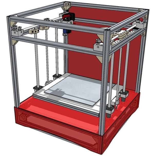
If you have vibrations on your Y-axis, it will be seen on the X side of the cube. If you have vibrations on your X-axis, it will be seen on the Y side of the cube.
Slowly test and adjust to get the settings just right.
Using Arc Welder to Improve 3D Printing Curves
There’s a Cura Marketplace Plugin called Arc Welder that you can use to improve printing quality when it comes to 3D printing curves and arcs specifically. Some 3D prints will have curves to them, which when sliced, translates into a series of G-Code commands.
3D printer movements are mainly made up of G0 & G1 movements which are a series of lines, but Arc Welder introduces G2 & G3 movements which are actual curves and arcs.
Not only does it benefit printing quality, but helps to reduce print imperfections like Ghosting/Ringing in your 3D models.
Here it looks when you install the plugin and restart Cura. Simply find the setting in Special Modes or by searching for “Arc Welder” and check the box.
It brings up a few other settings that you can adjust if needed, based mainly on improving quality or firmware settings, but defaults should work just fine.
Check out the video below for more details.
If you love great quality 3D prints, you’ll love the AMX3d Pro Grade 3D Printer Tool Kit from Amazon. It is a staple set of 3D printing tools that gives you everything you need to remove, clean & finish your 3D prints.
It gives you the ability to:
- Easily clean your 3D prints – 25-piece kit with 13 knife blades and 3 handles, long tweezers, needle nose pliers, and glue stick.
- Simply remove 3D prints – stop damaging your 3D prints by using one of the 3 specialized removal tools.
- Perfectly finish your 3D prints – the 3-piece, 6-tool precision scraper/pick/knife blade combo can get into small crevices to get a great finish.
- Become a 3D printing pro!
How To Tune 3D Printer Jerk And Acceleration Settings
If you’re constantly running into 3D printing issues which are not resolved no matter what you try, there are two lesser-known settings in your 3D printer that you may wish to tweak: the jerk and acceleration settings.
A word of warning: jerk and acceleration tuning is an advanced tactic, and we don’t recommend doing it until you’ve exhausted all other common issues like mechanical faults and filament quality.
With that said, the ideal settings for jerk 6-7 for the x and y-axis and 600 to 700 for acceleration. These numbers are a good place to start, and you can adjust up or down as necessary to get the ideal 3D printing results you are looking for.
If you like, you can go ahead and change the jerk and acceleration settings, get a benchy going on your 3D printer, and come back to this article for more information on how jerk and acceleration work!
What does the jerk setting do?
While the name may seem a little mean, the jerk setting is actually quite useful. To understand how it works, think of jerky movements. If you were running in a zig-zag motion with very sudden and abrupt changes in direction, you’d experience jerky movement.
The same thing goes for your 3D printer’s jerk setting: it determines how fast the print head moves from the stationary position and how much the print head will slow down before changing direction.
The higher the jerk value is, the print head’s movement from the stationary position will be faster, and the changes in direction will be more abrupt.
Of course, the jerk setting is limited by your print speed, so when your printer actually runs, the jerk setting works in conjunction with the print speed that you specified in the gcode.
As you can see, the jerk setting is quite nuanced: simply raising or lowering it will not magically fix your issues. They require tuning!
As a quick primer, this is what you can expect:
High jerk settings
- The 3D print will finish quicker as the print head is not slowing down quite as much.
- There will be fewer blobs as the nozzle does not stay in one position for long enough for extra plastic to drip.
- There will be greater vibrations as the speed is faster and the change in direction is more sudden.
- Corners and circles will be more accurate as the movement is faster
Lower jerk settings
- Less stress on the printer
- Movements smoother
- When the print head changes direction, the filament will stick stronger to the bottom layer.
- Less overall noise
Realistically, there will not be a huge difference in print times when you use higher jerk settings. For everyday 3D printing, you may not really notice the difference.
However, if the jerk value is too high, you will definitely see vibrations, so that’s something you need to watch out for when you increase the jerk setting.
What does the acceleration setting do?
While the jerk setting measures how fast the print head changes direction, the acceleration setting determines how fast the print head reaches the maximum print speed you’ve set in your slicer settings.
It’s worth noting that your printer does not always print at the maximum speed you enter in your slicer. For example, for a printer to reach a speed of 60 mm/s, it needs to travel 60mm! If your model size is smaller than 60mm, it can’t go that fast.
To see if your acceleration value and print speed match, you can use this super handy calculator by Prusa Research.
Also, some parts of the model, such as the first layer and supports or rafts tend to print slower.
Do you really need to adjust jerk and acceleration?
In most cases, the default acceleration and jerk settings in the 3D printer firmware are good enough for your 3D printing needs. If you’re not entirely sure what you are doing, you may mess up your 3D printing results if you change the acceleration and jerk settings too much.
Also, you may not be able to notice much of a difference when you change the settings!
However, there are certain cases where you may wish to try changing the settings if you’re not able to fix them using basic 3D printer maintenance or slicer settings:
- Making your printer less noisy
- Fixing Z-wobble
- Fixing a shaky or wobbly printer
- Fixing rough print surfaces
- Fixer skipped layer lines
- Removing ringing and unwanted blobs from your prints
For those of you that are getting good 3D printing results already and you feel you’ve nailed down your slicer profile, it’s worth experimenting with your jerk and acceleration settings to see if that makes any more difference.
Remember to note what values the settings were at and go back to those if anything goes awry!
Finding the ideal acceleration settings for your 3D printer
Teaching Tech has uploaded a really useful model to Thingiverse that you can slice with a layer height of 0.2mm and your desired print speed.
Once you slice it, you’ll have to go into the gcode file and manually add code to increase the acceleration value every 5 layers.
This way, you’ll be able to see all the different acceleration values in a single model!
Open the gcode file using software like Notepad++ or Sublime Text.
Scroll down until you find a comment that says Layer 1 (Simplify3D) or Layer:0 (Cura).
Below that, add the following:
M201 X3000 Y3000
M204 P400
Next, search for Z = 5(Simplify3d) or z5(Cura)
Below that, add:
M204 P800
Then search for layer 10, 15, 20, and 25, and keep adding 400 to the acceleration value for every 5 layers.
M204 P1200, M204 P1600, M204 P2000, M204 P2400
Save the gcode file and send it to your printer.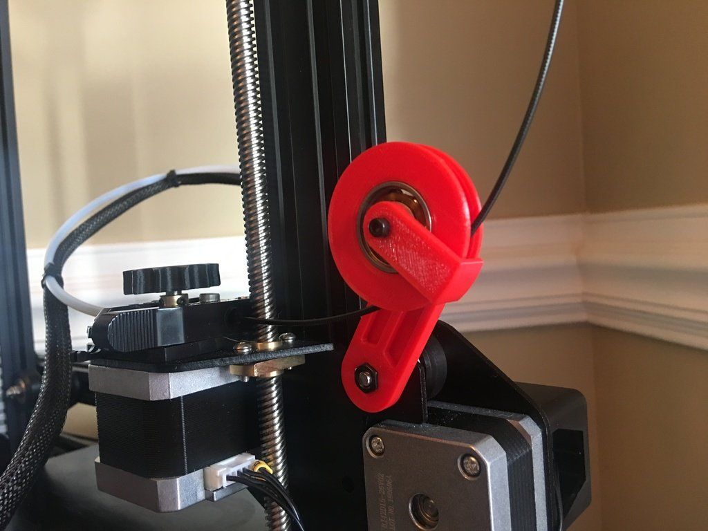
Once the print is complete, you’ll be able to see the differences the increased acceleration makes to ringing.
This will help you find a range that works best for your printer, which you can then hard-code into the firmware using the settings menu in your 3D printer.
Jerk vs. junction deviation
Older versions of the Marlin firmware use the classic jerk value, but the newer Marlin firmware uses a value called junction deviation.
To know what you’re using, you’ll need to use a program like Pronterface and send an M503 command to the printer.
Look in the M205 results:
If you’re getting X, Y, Z results, you’re using jerk.
If you’re getting a single J result, you’re using junction deviation.
Repeat the same test as you did with the acceleration test using the same model.
In the sliced gcode file, you’ll now enter M205 instead of M204.
For jerk, use the following values in 5 layer increments as you did above:
M205 X4 Y4
M205 X5 Y5
All the way up to 9.
If your firmware uses junction deviation, use:
M205 J0.01
M205 J0.02
All the way up to J0.06.
Teaching Tech’s tutorial is really superb, and I highly recommend you follow it:
Conclusion
As you can see, acceleration and jerk are really powerful ways to fine-tune your 3D prints. My only recommendation is that you attempt to tune these after you’re confident your slicer settings are really dialed in.
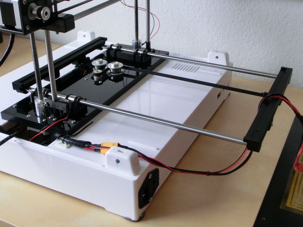
Instructions for setting up all the mechanics of a 3D printer: from belts to speeds
The quality of the printed models directly depends on the mechanics of the printer, namely on its correct settings. Any elements of the printer wear out over time, so the printer must be set up at least once every 5-6 kg of printed filament. With the help of the short instructions described in this guide, you can quickly and easily set up the mechanics of your printer: belt tension, motor current, motor steps, acceleration, jerk and speed.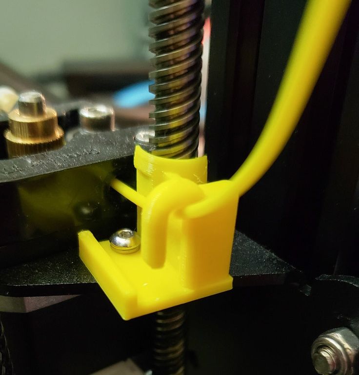
Mechanics includes
3D printers of any design always contain the same things: Axes and rails along which the elements of the printer move and motors with belts that set these elements in motion. In a classic printer design, there are at least 3 motors (one for each axis), 3 rails (one for each axis) and an electronics board that controls the motors. The latter can hardly be called part of the mechanics, but since it controls the engines, it also indirectly affects the quality of the model.
Printing defects due to mechanical problems
Before changing anything in the printer, you need to decide what exactly needs to be configured. Often defects are visible visually. Our blog has an article about most printing defects, which details the reasons for their occurrence. The following is a list of defects and what element of mechanics they are associated with:
-
Layer shifting - Belts, Motor current, Guides
-
Ringing - Guides, Speed
-
Incorrect model geometry - Guides, Motor steps, belts
As you can see, all the above problems do not interfere with the printing process itself, but the result leaves much to be desired. Sometimes mechanical errors can completely stop the printer from working. Therefore, it is better not to take the situation to extremes and, if any problems arise, immediately start checking and configuring the 3D printer.
How to save settings
To fix some defects, you need to change the printer software settings. Therefore, before adjusting the mechanics, it is necessary to understand how to properly store the settings inside the printer. There are 3 ways to do this:
All settings are located in the corresponding menu of the printer
Depending on your firmware, this manual will indicate code sections for MARLIN firmware in the configuration.h file
We first enter the parameters into the printer and then store them in EEPROM - the internal memory of the microcontroller. Or paste all the necessary settings at the beginning of GCODE. To learn how to do this, read our article on working with GCODE and creating macros.
To save to EEPROM, you need to send the printer a command to change some value (which can also be inserted into the initial GCODE), and then send the M500 command (save the current settings to permanent memory). The EEPROM function must be enabled in the firmware, for this you need to remove two slashes in the line:
//#define EEPROM_SETTINGS
Whichever option you choose, you should be careful when using any commands. You will not be able to harm the printer in any way when changing the settings, but if you make a mistake, you will have to look for the cause of possible further problems for a long time.
Setup instructions
Now you can start setting up the printer itself. If you decide to set several parameters at once, then it is better to use the order of adjustments as in the article, since some of the settings are related to each other and if you use the wrong order, adjusting one element of the mechanics will override the settings of another element. For example, you should not adjust the motor steps before tightening the belts, as changing the length of the belts will change the "true" steps per millimeter of the motors. Also, before setting up, you must make sure that there are no backlashes in the printer frame, tighten all belts.
Belts
The first thing to start setting up the printer is the belts. They directly affect the geometry of the model and, when pulled too much, they cause a lot of problems: displacement of layers, changes in geometry, ripples. First you need to make sure the belt is intact. To do this, look at the entire belt, especially the areas where the belts bend. If the belt has outlived its usefulness, then you can see a section of the belt where the distance between the teeth has greatly increased and a metal wire (cord) is visible between them. This means that it's time to completely change the belt.
Broken belt with broken cords
If the belt is intact or you have already replaced it, then you can proceed to the next step. Depending on the design of your printer, you need to move the roller through which the belt passes. The tension should be such that the carriage or table moves effortlessly, but at the same time, when moving quickly, the belt should not slip the teeth on the motor gear.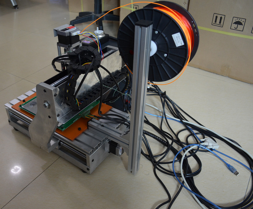 Adjust the tension of the belts on each axis of the printer using this method.
Tip: if your printer came with a belt tensioner in the form of a spring attached to the belt itself, remove it. Due to the flexibility of this tensioner, printing defects will occur, such as protruding corners on the model. It is better to adjust the belt without using this tensioner.
Belt tensioner
Current motors
As we know from the school physics course, the power of the engine depends on the voltage and current strength. Since the voltage on all printer electronics is the same everywhere, the only thing that can be changed is the current on the motor. More precisely, it should be said the maximum current that the driver will supply to the motors. To change this limit, you need to climb inside the case and find the printer board. On it you will see the printer driver. We are interested in a small potentiometer on the driver itself (in the picture below it is indicated as a tuning resistor).
Potentiometer location example on driver
For adjustment, you will need a voltmeter and a small Phillips or flathead screwdriver. Before proceeding further, it is necessary to calculate the maximum current supplied to the motors. Different formulas are used for different drivers, the most popular ones will be listed in the table below:
| Driver name | Formula | Explanations |
| A4988 | Vref = Imax * 1.25 for R100 | To understand which formula to use, you need to find a resistor with the signature R100 or R050 on the driver. They are located next to the driver chip. |
| DRV8825 | Vref = Imax / 2 | |
| LV8729 | Vref = Imax / 2 | |
| TMC2208 TMC2100 TMC2130 | Vref = Imax * 1. | One formula for all drivers |
 41
41 The value of the maximum current (Imax) depends on the motor controlled by the driver. This can be found in the engine specification or on the sticker on it. The following are the currents for the most popular motor models:
17HS4401 - current 1.7 A
17HS8401 - current 1.8 A
17HS4402 - current 1.3 A
Substituting the value into the formula, we get the Vref value for the maximum current supplied to the motor. But at this value, the engine will get very hot, so the resulting Vref value must be multiplied by 0.7. For example, for a motor with a maximum current of 1.5 A and a TMC 2208 driver:
Vref=1.5*1.41*0.7=1.48V
Now the resulting value can be used when configuring on the printer itself. To do this, disconnect the wires going to the motors, turn on the printer and place one voltmeter probe in the center of the trimmer, and the second probe to the negative terminal on the power supply (you can also use the negative terminal on the printer board and the contact on the driver, labeled as GND).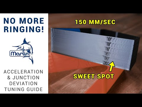 You will see some value on the voltmeter screen. Turn the trimmer clockwise to decrease the Vref value and counterclockwise to increase it.
Attention: you should not specify a Vref value higher than the maximum calculated for your engine! Otherwise, the engine will soon break down!
Once you have adjusted the value on the drivers, you can turn off the power to the printer, connect the motor wires, and put the case back together. This completes the driver setup.
Motor steps
When setting up motor steps, you will need a ruler. For convenience, you can use the program Repetier-Host. The adjustment for each of the three axes occurs according to the same algorithm:
-
Set the caret to zero coordinates (Autohome or G28)
-
Move the carriage some distance
-
We measure how far the carriage has traveled
-
We calculate the correct number of steps per millimeter using the formula:
True steps per millimeter = current steps per millimeter * reported distance / distance traveled
For example, if the printer was set to 100 steps/mm, we tell the printer to move 80mm and the printer travels 87.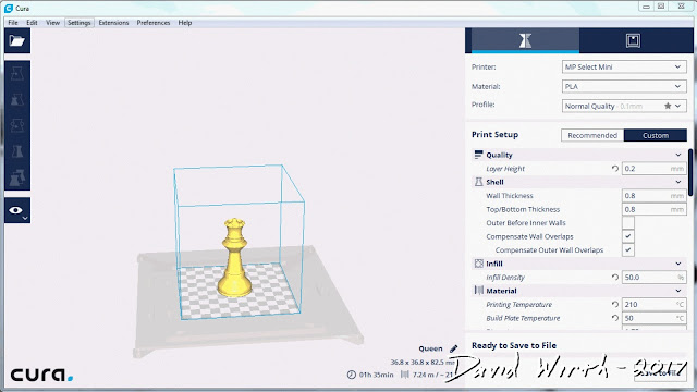 5mm. Then the correct steps per millimeter would be 100 * 80 / 87.5 = 91.42 steps/mm. For the convenience of measurements, you can fix a ruler on the table, and a thin object, such as a needle or pin, on the carriage. Then it will be possible to accurately measure the distance traveled. The extruder uses a partially different algorithm to measure distance:
-
Inserting plastic into the extruder
-
Cut it right at the outlet
-
We give the printer a command to stretch the plastic a certain distance (at least 100 millimeters)
-
Cutting plastic again
-
We measure the length of the resulting piece of plastic
-
We use the formula from the previous algorithm
Next, the settings data must be inserted into the firmware in the line:
#define DEFAULT_AXIS_STEPS_PER_UNIT {X,Y,Z,E0}
X,Y,Z and E0 should be replaced by the steps per millimeter for each of the axes, respectively.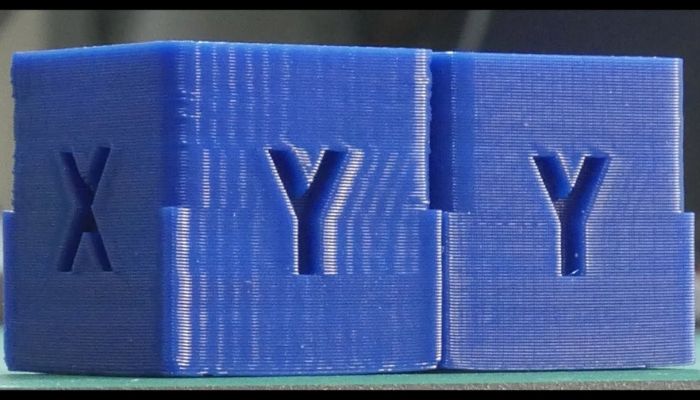 Otherwise, you need to insert this line into the initial GCODE:
M92 Ennn Xnnn Ynnn Znnn
Instead of nnn in each of the parameters, you must substitute the steps per millimeter for each axis. If you want to adjust the steps only for not all axes, then you can remove unnecessary parameters.
Acceleration
This parameter is responsible for the rate of change of speed. That is, how fast the printer will change its speed. This affects the nature of the movement of the hot end relative to the table. If the acceleration is too small, then the printer will print slowly, if it is too large, then the outer surface of the model will have visual defects: fading waves will be visible near each of the corners, as in the picture below.
To set up acceleration, you need to follow simple steps:
-
Cut a model of a standard test cube with a wall thickness equal to one nozzle diameter, without filling and top layers, bottom 2-3 layers;
-
Open GCODE file in notepad;
-
Find the G28 command at the very beginning and insert the line data after it:
M201 X5000 Y5000
M204 P500 T500
-
Save the changes, print the model according to the received GCODE and note at what parameters P and T it was printed;
-
Open the same GCODE file and change the P and T values on the second line, adding 500 to each;
-
Repeat steps 4-5 at least 3 times;
As a result, you will get several test cubes, some of which will show waves at the corners. Choose the cube that is printed with the highest P and T parameters, but that no waves can be seen on it. The number in parameter P will be the desired acceleration value. To save this value, you need to find 2 lines in the firmware:
#define DEFAULT_MAX_ACCELERATION {X,Y,Z,E0}
#define DEFAULT_ACCELERATION {nnn}
Instead of X and Y, you should put an acceleration twice as high as found earlier. And instead of nnn, you need to put the acceleration value found earlier. Otherwise, you need to insert a line in the initial GCODE:
M204 Pnnn Tnnn
In the parameters P and T, you need to put the value of the found acceleration. After that, the acceleration setting can be considered complete.
Jerk
A jerk indicates the speed with which to start accelerating. It affects the model in a similar way as acceleration: it creates ripples around the corners of the model. But it also increases the protrusion of the corners if the jerk is too small. The jerk setting is also similar to the acceleration setting:
-
Cut a model of a standard test cube with a wall thickness equal to one nozzle diameter, without filling and top layers, bottom 2-3 layers.
-
Open GCODE file in notepad
-
Find the G28 command at the very beginning and insert the line data after it:
M205 X5 Y5
-
Save the changes, print the model according to the received GCODE and note at what X and Y parameters it was printed
-
Open the same GCODE file and change the X and Y values on the second line, adding 2 to each
-
Repeat steps 4-5 at least 3 times
As a result, you will get several cubes. Find a non-rippled cube printed at the highest X and Y settings. This will be the jerk value for your printer. To save them, you need to find the line in the firmware:
#define DEFAULT_XJERKnnn
#define DEFAULT_YJERKnnn
It is necessary to substitute the jerk values for the X and Y axes, respectively. Otherwise, you need to substitute the command in the starting GCODE:
M205
Instead of nnn, you need to substitute the jerk value found earlier. This completes the jerk setting.
Speed
In fact, there are many different speed parameters, the values \u200b\u200bof which vary greatly. Let's take a look at the main ones:
This parameter is responsible for moving the nozzle without extruding plastic. The value is in the range from 80 to 120 mm/s. Limited only by the maximum speed at which the motors can rotate. Does not affect the model
This speed is important because it indirectly affects the adhesion of the model to the table. Usually lies between 15 and 30 mm/s
-Print speed of inner walls
Usually set to about 60 mm/s, it only affects the strength of the model. Depends on the maximum amount of plastic that the extruder can push through the nozzle
-Speed of printing outer walls
Usually about half the printing speed of the inner walls (30 mm / s). It affects not only the strength of the model, but also the appearance: the lower this speed, the smoother the walls will be.
The standard value is 80 mm/s, it only affects the strength of the model
Usually set from 20 to 40 mm/s, the quality of the upper layer of the model depends on it: the lower the value, the smoother the cover.
All of the above parameters are selected experimentally. Usually there is a simple rule: higher speed - lower quality. Therefore, do not try to find the ideal value for all situations. It is better to find values for fast printing, quality printing, and an average that will be used for most models.
Check settings
The last step in setting any of the above parameters will be to check the result. If you have written parameters in firmware or saved them in EEPROM, you can use the M503 command. It will display all printer settings on the computer. To test the settings in practice, you can print several test models:
Classic Benchy
Simple calibration cube
Calibration cat
On each of the above models, defects will be clearly visible, if they still remain after the mechanics are adjusted.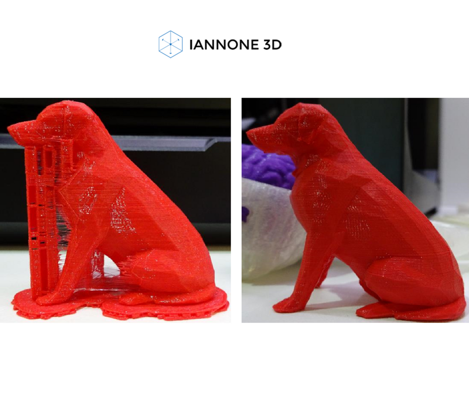
3D printer speed: how to set it right?
3DPrintStory 3D printing process 3D printer speed: how to set it up correctly?
3D printing is often referred to as "rapid prototyping". The irony is that the creation of individual models can take up to several hours. Fortunately, 3D printing speed can be adjusted to reduce production time, but setting the speed incorrectly can also lead to defects and 3D printing failures.
In this article, we will introduce you to the general speed settings of a 3D printer. By the end of this guide, you'll know how to find the perfect balance between print speed and quality. Please be aware that different 3D printers, slicing software and materials may behave differently and retesting may be required.
So, run the slicing software and let's get started!
3D Print Speed
3D Print Speed is the main setting that affects the printing of your 3D model. As the name suggests, print speed determines how fast your printer's motors move. This includes the motors that control the X and Y axes, as well as the motor(s) of the extruder.
To test your 3D printing speed, download the test model above to determine the optimal print speed. The description of this 3D model also contains recommendations for speed settings. In essence, the experiment is that the same model will be printed, but at a gradually increasing speed, which will allow you to visually determine the optimal speed setting.
Too low a 3D print speed can cause deformation due to the nozzle being on the plastic for too long. If too fast, other overheating artifacts may appear, caused by insufficient cooling, as well as extrusion and poor adhesion of the layers. The optimal speed should be as fast as possible for your 3D printer without compromising print quality too much. This 3D model will help you determine what speed will be optimal for your particular case.
To optimize print speed, this parameter is usually divided into several sub-parameters:
- Outer Wall/Shell 3D Print Speed : This parameter controls the print speed of the outer perimeter of the model. Usually it is slightly reduced to improve the surface quality.
- Inner Wall/Shell 3D Print Speed : This setting controls the print speed of the inner perimeter(s) of the model. It is usually the same as the overall print speed to reduce print time while maintaining durability.
- Infill 3D Print Speed : This parameter controls the infill print speed of the model. This is usually the same as the overall print speed to reduce 3D printing time while maintaining strength.
- Top/Bottom 3D Print Speed : This setting adjusts the print speed of the top and bottom of the model. Usually it is slightly reduced to improve the surface quality.
Travel speed (idle)
Travel speed controls how fast the print head moves when it is not extruding plastic. Increasing the movement speed can save a lot of 3D printing time, but increasing it too much can lead to many defects, including misaligned layers (and therefore 3D printing failure).
To determine the optimum idle travel speed for your printer, print this test pattern at various travel speeds, starting at 100 mm/s and working up in increments of 5 mm/s. Continue to increase the speed if the surface quality is acceptable, and decrease if the 3D print quality is deteriorating. Pay attention to defects such as mismatched layers.
Retract Speed
Retract Speed controls how fast the 3D printer pulls material back before moving. This setting is critical for reducing material waste and improving 3D print quality. Too slow and you may be left with unsightly threads and blemishes on your models. Too fast and you can get excessive material wear on the extruder drive gear, resulting in voids.
To determine the optimal retract speed for your 3D printer, print this test model at various retract speeds starting at 25mm/s and adjusting in 5mm/s increments. Pay attention to the remnants of plastic in the form of a web, stretched between the spikes of the model. The ideal retract speed should be the maximum value that minimizes these artifacts without deforming the material in the feed mechanism.
To better tune the retract speed, this parameter is usually divided into two additional parameters:
Retraction Retract Speed : This parameter controls how fast the retract (actually pulling the thread back) occurs. This is usually the same as your overall retract speed and is set the same way.
Retraction Prime Speed: This setting controls how quickly the filament is re-feeded after the initial retraction in preparation for further printing. Increasing this speed will result in shorter 3D printing times and fewer defects due to prolonged exposure to heat on the plastic. However, increasing it too much can also cause the newly fed media to not heat up enough before printing resumes. For most cases, this setting should be left the same as Retraction Retract Speed.
To learn more about reducing retraction speed defects, see our separate guide to retract speed tuning.
Walls, infill and layer height
The speed of your 3D printer is not only affected by "speed". It is also significantly affected by how much and how thick plastic is extruded onto each layer of the 3D model. These settings are incredibly detailed, so we'll only cover general information about how each of them affects 3D print speed.
- Walls : The wall setting specifies how many perimeters of plastic are extruded to form the outline of your part. Increasing the number of layers increases the strength of the part, but also increases the 3D printing time.
- Infill : Infill is an internal structure designed to save material when 3D printing the interior of 3D models.
Learn more