3D printing from blender
Can Blender be used for 3D printing?
Published on March 2, 2020 by Carlota V.
Created in 1995, Blender is a complete 3D modeling software, very popular in the world of animation and video thanks to the many features it offers. The particularity of Blender is that it is 100% free, open source – which is why it is constantly being improved – and that it benefits from a large community that regularly meets around the world to share best practices and user challenges. Based on polygonal modeling, it is not necessarily the most widely used solution in the additive manufacturing sector, but it does allow 3D models to be exported in formats adapted to the technology. Let’s go back to the main features of the Blender software!
The Blender solution was initially designed for an animation studio and was not intended to be shared worldwide. But the software quickly became open source and today, the Blender Foundation (the association behind the developments) estimates that there are 3 million users worldwide. The software includes various functionalities grouped into a dozen families: modeling, animation, simulation, video editing, 3D rendering, etc. It is rather oriented towards animation studios, artists and small teams working on video creation or cinema – several “Open Movies” are made on Blender. One of the latest is called Spring:
Blender is based on polygonal modelling
As you know, 3D software offers different modelling methods: surface, solid or organic. Here, Blender uses polygons to create a three-dimensional shape. The designed model is therefore composed of a multitude of polygons (or facets) that form what is called the mesh. Each polygon is composed of vertices, edges and faces. By assembling different polygons, a basic shape is obtained: for example, the interlocking of 6 polygons will form a cube. The next step is to deform basic shapes, and to agglomerate them together to design basic objects: 9 deformed cubes will become a chair for example. The user can then play with the edges and move points to progressively add complexity the model.
This method of modeling is quite intuitive because the user can move edges and points in space to deform the model until arriving at the desired shape. It also allows to have a greater complexity than through surface processes. On the other hand, it does not offer the best dimensional accuracy because the 3D model is the result of successive subdivisions. This is a major obstacle when it comes to obtaining a stable geometry for additive manufacturing.
Software features for 3D printing
We won’t go back over all of Blender’s features (animation, video, 3D rendering, etc.) because it’s really the 3D modeling part that interests us for 3D printing. You should know that the software offers export formats for additive manufacturing such as STL file but also OBJ file. However, polygonal modeling does not seem to be the most intuitive way to design printable parts. Blender still offers a feature to be added to its software called “3D Printing ToolBox”. This will allow you to analyze your mesh to identify some errors that could cause your printing to fail. For example, this toolbox can check the minimum thickness of your walls or the geometry of overhangs.
The ‘3D printing toolbox’ enables you to check your model before 3D printing
Blender is therefore not the 3D software most used by 3D printing enthusiasts but it has the merit of being free, open-source and regularly improved by its entire community. We recommend a software more accessible to all beginners like TinkerCAD for example, and Fusion 360 for the most experienced. You can download Blender HERE, the solution is compatible on Mac, Windows or Linux.
Do you use Blender? Let us know in a comment below or on our Facebook and Twitter pages! Sign up for our free weekly Newsletter, all the latest news in 3D printing straight to your inbox!
Blender Tutorials - Learn Blender
Have you been thinking about learning how to use Blender, but you open the window and see all this and get really confused? Well I’m here to help with that. My name’s Kevin, founder of Inventimark and I hope you enjoy these tutorials.
Blender Introduction Tutorial #001 The Basics
This tutorial is where you want to start when learning 3D modeling with Blender for 3D printing. Here you are shown the basics of Blender and the basic workings of the program. It’s a small step into the vast possibilities of the computer 3D world.
Introduction Tutorial #002 The Basics part 2
In this second part of this tutorial, you will learn about the different camera views and how each of them work. You will also be shown the most common keyboard shortcuts that are very helpful in creating a fast work flow to 3D Modeling.
Tutorial #003 Making a Simple Glass
In this modeling practice, you are taught how to make a simple glass. There is also an explanation of some of Blenders other features, showing you how to render your model to get a good picture of it.
Tutorial #004 Making an Action Cam Clamp
This modeling practice lesson will teach you some of the basic modeling techniques and uses, to make a practical design that can be used in the real world when printed.
Tutorial #005 3D Printing Functions
This tutorial demonstrates Blenders 3D printing specific features. Non-Manifold objects are also explained and why they are important to avoid.
Tutorial #006 More Basics of the UI
This lesson explains in more detail some of the user interface to get you more familiar with using it.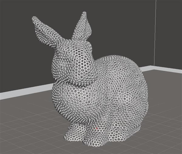 Also shown is the sculpting features and some abstract modeling is made to demonstrate its uses.
Tutorial #007 : Loop tool and Proportional Editing
This tutorial shows you how the edge cut tool works. Also shown is how proportional editing works to make object re-shaping smoother.
Tutorial #008 : Pivots and Startups
In this tutorial, the pivot point/origin is shown, as well as how to save the startup files to keep your settings.
Tutorial #009 : Project box
In this tutorial, is another practicing session on practical 3D modeling. Shown is a project box for a solar powered automatic watering system using several different components.
Tutorial #010 Nurbs Curves and Surfaces
In this video, examples of using curves to model are shown. Also featured is how to make solid objects and how to mirror objects.
Tutorial #011: Text Basics
This tutorial shows the text features in Blender, and how to integrate text into your models.
Tutorial #012 : Measurements
This video explains the different measurements in Blender that can be used. Examples are show with Unity, Unreal Engine 4, and Repetier-Host. This video also explains that Blender units as 1mm are the best to use for 3D modeling.
Tutorial #013 : Background Image + Bonus
This video demonstrates how to use a background image to get a precise model from an image. Shown as example is an E3D-V6 hot-end heat sink. The image used was acquired from http://wiki.e3d-online.com/.
Tutorial #014 : Practical Modeling Practice
This is a longer practical modeling practice showing how to make a linear bearing with 3x8x4mm bearings and M3 bolts and nuts. There are errors and troubleshooting to show how to deal with that as well.
Tutorial #015 : How to Make Gears
This video demonstrates how to make gears for a 3D printer extruder. This process can be used whenever any 2 gears are used.
Tutorial #016 : Loop Tools
This video demonstrates all of the Loop Tools and how they are used. Some of these tools are great for 3D printing, others are rarely used.
Tutorial #017 : Splitting Model for 3D print
This video demonstrates a crudely made model and how to split the model up into different parts for easier printing. This will for for any size model.
Tutorial #018 : Knife Tool
This video shows a model of a Bowie knife the author made. What is taught in this tutorial, is how to use the knife tool and shows what it does as well as other knife features.
Tutorial #019 : Torture Calibration
This video is another practical modeling practice that shows you how to make a calibration/torture test for your 3D printer to get the dimensions correct.
Blender 3D for 3D Printers / Sudo Null IT News
Correct position! But some problems can still be covered by polygonal modeling.
Gathered here the answers to the four most common and non-obvious problems.
Dimensions
When I first tried to order 3D printing from a company about seven years ago, it was like this:
— Igor! You sent an empty file!
- No! Here's a screenshot, well!
One meter in the Blender is equal to one millimeter in the slicer, nothing has changed in these seven years.
Designing in meters is wonderfully inconvenient, so when exporting to STL/OBJ, set the Scale value to 1000:
Closed geometry The ability to create open geometry is both a scourge and a bonus of polygonal modeling.
In the modern world, slicers (not all) have learned how to work with this, but there may be surprises: want a hole? get a blank wall!
If you don't like surprises, you should use Blender's geometry analyzer.
In mesh edit mode, select vertex selection, and click Select → Select All By Trail → Non Manifold
To eliminate such trash as on the right ball, there is a Merge By Distance tool. Lives in Mesh → Clean Up → Merge By Distance.
In other cases, it is necessary to either give the wall thickness by extruding, or close up the hole, or is this geometry really necessary?
And now for the good news: in Blender 2.8 the 3D printing addon is built right into Blender, hooray! Geometry analysis just got easier. You just need to turn it on, and in the edit mode in the N-panel everything will be (and even the preliminary volume of the model!).
Flying geometry
As unclosed, only flying. So the slicer can still try to shove it into the G-code!
The annoyance is that if the volume of the walls was made by a modifier, these mesh pieces can no longer be found with the Non Manifold tool.
Select any polygon on the target mesh, and use the Ctrl+L hotkey: it will add all physically connected polygons to the selection. After that, invert the selection with the Ctrl+I hotkey and delete everything you don't need.
Normals
Roughly speaking, the polygon has a "face". When the polygon enters the slicer, the slicer looks at where the polygon has a “face”, tries to fill the wrong side with plastic, and at the same time checks for overhangs.
Accordingly, a cube with normals inside will be perceived clumsily. In fairness, in modern slicers this is no longer so important.
The solution is super-simple: turn on the display of normals:
Flip in the right direction: select the polygon with the normal turned inside out and press Alt+N. Hoba! and the slicer no longer panics about negative angles where they cannot exist.
Generalize
Blender, indeed, is not developed as engineering software, and you should not try to solve furious tasks with it in the spirit of multicomponent kinematic systems.
But the blender + home 3D printer perfectly covers the needs of a small workshop, the main thing is to remember the nuances of polygonal modeling.
Preparing files for 3D printing in Blender
Share on Facebook Share on Twitter Share on Vkontakte
Look for open edges
If your 3D model consists of several objects or polygon meshes, the first thing you need to do is make sure that the edges of each part are closed, in other words, waterproof. To do this, you need to enter edit mode by pressing A (once to select any faces, twice to deselect), then you need to press the key combination ctrl-alt-shift-M (on Mac computers - ctrl-opt-shift- M).
After you press this key combination, all open faces will be selected. Often, to fix this error, you need to create a new surface with 3-4 faces (F key). Sometimes there are wandering edges that are either not attached to anything, or connected to only one edge vertex. Often they can be safely removed, unless they were specially made. For example, these faces can be used to shape the model using the Subsurf modifier. In this case, you will need to apply this modifier first, and only then remove the unnecessary edges. In addition, do not forget about those open faces that are part of the intersecting surfaces.
If your model has 3-4 attached polygons that the software sees as open but says that a surface has been created, you need to delete that surface and try to recreate it. Moreover, inspect the edges of all those faces that were marked as open. Perhaps some of them are wrong: they do not belong to the polygon mesh or they are created in the wrong direction. In this case, you will have to delete this block and recreate it manually.
Tip: Hide the geometry to focus on the uncovered areas So, you can select not only open faces, but also the areas around them. Next press shift-H to hide the other edges. In this way, the closed parts of the model will be hidden, and it will be much easier for you to eliminate all the flaws.
Cleanup: Merge meshes using Booleans.
Once all the meshes are closed, make sure that each one represents a separate feature. You cannot apply boolean variables to polygon meshes that refer to the same object. At the same time, it is possible to split the meshes by selecting all its faces and pressing P. Next, select one vertex, then, holding ctrl, select all the others. To detach all polygon meshes of one object, press P and select the "All Loose Parts" option.
Once you've separated all the meshes into objects and made sure they're closed, save the project and save a copy of the blender file to create a printable version of it.
Open a copy of the file and select each object one at a time. In object mode, apply any modifiers you want. Next, go into edit mode by pressing the A key once or twice to select all the faces. Then press ctrl-T to triangulate all surfaces. It is not clear what this is connected with, but Blender works better with booleans if the meshes have been triangulated.
Return to object mode again, select 2 mutually intersecting meshes and press w. Then select the Union option, after which the meshes will be merged (this action does not delete the sources). The merging process may take some time. Once it completes, select the 2 original objects that were merged and either move them to another layer or delete them altogether.
Select the new, merged object, go to edit mode, deselect the edges (press the A key 1-2 times), then select the unclosed areas - ctrl-alt-shift-M. Fix these errors in edit mode, it will be pretty easy. Often, combining polygon meshes solves the problem of open areas, but not always. Therefore, we recommend that you still check your model. Otherwise, when further merging meshes that have open areas, you may have problems. Check it EVERY TIME. Then select all meshes and triangulate again. As a result, you will get a single mesh with closed faces that has been triangulated. Such a mesh is completely ready for further merging, if necessary.
If you have 2 meshes with incommensurable face density, such as when a rounded mesh is merged with a cube that has 8 vertices, subdivide the part with the fewest vertices.