3D printing from autocad
What is 3D Printing? | 3D Printing Software
What is 3D printing?
3D printing, also called additive manufacturing, is a family of processes that produces objects by adding material in layers that correspond to successive cross-sections of a 3D model. Plastics and metal alloys are the most commonly used materials for 3D printing, but it can work on nearly anything—from concrete to living tissue.
Featured 3D printing software
What is 3D printing used for?
Efficiently make one-off parts and create highly complex geometries that are only possible with 3D printing.
-
Prototyping
3D printing has long been used to quickly create prototypes for visual aids, assembly mockups, and presentation models.
Learn more
-
Lightweight parts
Fuel efficiency and emissions reductions are driving the need for lightweight parts via 3D printing in aerospace and automotive applications.
Learn more
-
Functionally enhanced products
3D printing removes many of the constraints imposed by traditional manufacturing processes that prevent engineers from truly designing for optimal performance.
Learn more
-
Custom medical implants
To achieve osseointegration, manufacturers are using 3D printing to precisely control surface porosity to better mimic real bone structure.
Learn more
-
Toolings, jigs, and features
3D printed composite tooling and machining fixtures are often cheaper and faster to produce, and conformally cooled inserts for injection molds can dramatically reduce cycle times.
Learn more
-
Metal casting patterns
Combining 3D printing with metal casting bridges the gap between generatively designed parts and proven manufacturing approaches for large metal objects.
3D printing processes & materials
Understanding the different additive manufacturing processes
Explore different additive manufacturing processes and technologies to help you find the right one for your workflow.
Learn more
What materials can be 3D printed?
Using the right material for your 3D printed project can make or break a product. This article will cover what materials can be 3D printed.
Learn more
How is 3D printing software used?
-
Granta
Mexico City start-up disrupts medical-implant manufacturing
Mexico City start-up Granta is changing medical implant design and fabrication for patients who suffer head trauma.
Read story
Image courtesy of Granta
-
Airbus
Airbus bionic partition
Airbus uses generative design and 3D printing to create a strong yet light cabin partition for the A320—and takes the first step toward the plane of the future.

Read story
Image courtesy of Airbus
-
Stanley Black & Decker
A computer designed Stanley Black & Decker’s new tool
Using generative design and 3D printing, Stanley Black & Decker’s Infrastructure Innovation Center is exploring new approaches to creating high-performance industrial tools.
Read story
Image courtesy of Stanley Black & Decker
Future of 3D printing
-
What does the future of 3D printing look like?
3D printing has come a long way from the early days of desktop figurines. As technology continues to evolve, the future is brighter than ever.
Learn more -
How 3D printing is revolutionizing the medical industry
Amidst a global healthcare crisis, 3D printing has become a flexible solution to modern medical challenges.
Learn more -
The future of additive manufacturing in aerospace
Learn about how aerospace companies are buying into additive manufacturing and what it means for the industry’s ongoing success.

Learn more
3D printing tutorials
-
How to SLICE 3D Prints with Fusion 360
Fusion 360 can slice models for 3D printing, without the need to save the file as an STL. In this tutorial, we'll take a design model into the Manufacture workspace. From there, we'll slice it, simulate the 3D print, and save the Gcode.
Watch video
-
Fusion 360 Additive for your Ultimaker 3D printer
This video details the FFF workflow along with tips and tricks to utilize Fusion 360 Additive FFF for a Ultimaker 3d printer.
Watch video
-
Fusion 360 for 3D printing FDM technology workflow
Learn more about the design process using fused deposition modeling (FDM) 3D printing technology through the power of a very flexible modeling workflow in Fusion 360 software.
Watch video
3D printing & sustainability
How sustainability and Fusion 360 can help you save money and the planet
Find out how you can use Fusion 360 software to drive efficiencies and innovation in your processes that will benefit your bottom line and the planet.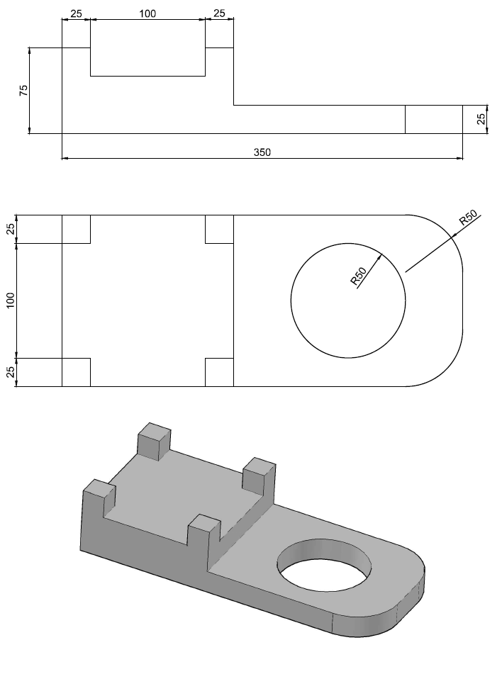
Learn more
Three environmental considerations for the FFF 3D printing process
Every manufacturing process, including FFF 3D printing, has an environmental impact. Learn how to reduce your parts' environmental footprint.
Learn more
Do your actions match your ambitions for success?
Get the right tools to achieve your new possible. Extensions amplify the functionality of Fusion 360 by unlocking advanced capabilities for machining, additive manufacturing, generative design, nesting, and fabrication. Discover Fusion 360 extensions.
Try Extensions
How long has 3D printing technology been around?
3D printing is much older than you might think! The first patents for an additive manufacturing process are dated all the way back to the 1970s. The first true additive manufacturing patent that led to a product is dated to 1984. The first real-world applications of additive manufacturing are in the dental industry, printing out masks of teeth as a replacement for plaster casting from molds.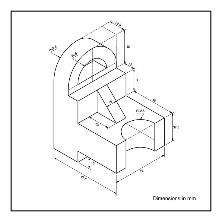
What are the benefits of 3D printing?
3D printing is a rapid prototyping process, mass customizable manufacturing process, and a technology that enables the creation of complex geometries previously not possible through other manufacturing processes. It’s also a digital manufacturing technology that requires no tooling changes for revised parts, which means there’s no downtime between product revisions or manufacturing entirely new products.
How much does it cost to 3D print something?
3D printing a part is a combination of the material you wish to use, and the volume. Because 3D printing can output using a plethora of plastics and metals, the cost of a part can vary dramatically depending on what you are using, but it can be more affordable per part than other processes.
What 3D printing services does Autodesk offer?
Autodesk offers Netfabb as a dedicated additive manufacturing prep, analysis, and simulation tool, as well as Fusion 360, which has a dedicated additive manufacturing space, marrying design, engineering, simulation and manufacturing all together.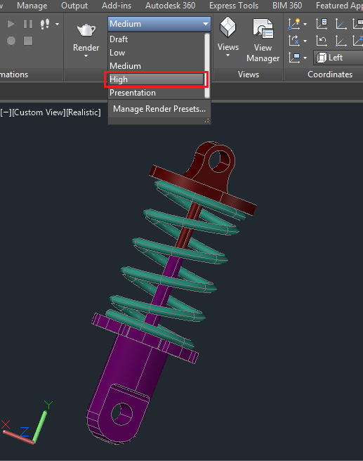
Fusion 360 is an excellent choice for creating CAD models for 3D printing. It allows you to create not only “prismatic” models such as gears or brackets, but it also allows you create more “organic” models using T-Splines, including characters, plants, and vehicles. You can use Fusion 360 to create and then edit your objects for 3D printing. Bring in models from other software and make modifications, such as de-featuring them by removing small features or blends. Fusion 360 can export as an OBJ or STL file format that is read by most 3D printing software. It also has the ability to print directly to your 3D printer. In addition, Fusion 360 even allows you to edit mesh or STL data that is brought in from a laser-scan or other source. Before printing, you can reduce or increase the surface count, edit out features, fill holes, etc.
CAD 3D printing software allows you to conceptualize, design, and optimize your models for fitting production technologies
Free resources for 3D printing
-
Additive manufacturing resource center
Access a variety of resources designed to help you identify how you can add value to your products with additive manufacturing.
-
Learn how to use Tinkercad to model, align and group parts, cut holes, add custom text, and specify dimensions. Tinkercad allows you to export and download designs for laser cutting and 3D printing to send designs to Autodesk® Fusion 360.
-
Learn how to take your ideas to reality through the use of design in Fusion 360 software, and how to utilize 3D printing to manufacture your idea.
-
Get product updates and enhancements, useful Fusion 360 tips and tutorials, roadmap updates and community stories.
-
Stay current with the latest in 3D printing trends and Netfabb software updates.
-
Learn how to print a PPE face shield in under four minutes and large-scale additive manufacturing.
AutoCAD: All You Need to Know Before Getting Started
Published on July 8, 2022 by Carlota V.
AutoCAD enables the professional creation and editing of 2D geometry and 3D models with solids, surfaces, and objects.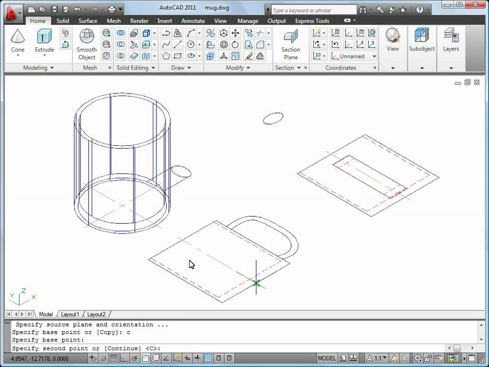 It is one of the most internationally recognized CAD software because of the wide variety of editing possibilities it offers. For these reasons, it is a tool widely used by architects, engineers and industrial designers, among others. Currently, the software is developed and marketed by Autodesk, a leader in the market of design, engineering and 3D animation software. Founded in 1982, Autodesk, a multinational company, began its adventure with the development of AutoCAD before moving on to other software solutions, some of which specialize in additive manufacturing.
The first version of AutoCAD included only a modifiable drawing and a limited set of functionalities. Despite its simplicity, it was at the time a real revolution as it allowed to replace traditional hand drawings with a digital drawings. The name AutoCAD refers to Autodesk of course but also to Computer Aided Design. Initially, the software was not designed for 3D design, it was only dedicated to two-dimensional modeling. AutoCAD has rapidly evolved: so what are its features today?
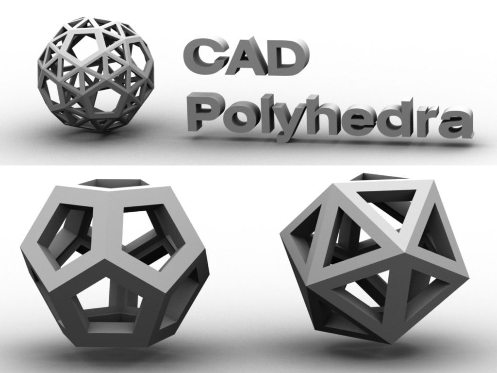
AutoCAD is one of the most popular CAD software on the market
How Does it Work?
AutoCAD software is available for MAC and Windows, and supported programming interfaces include ActiveX Automation, VBA, AutoLISP, Visual LISP, ObjectARX, and .NET. However, the type of interface to be used will depend on the programming needs and experience of the user. On the Autodesk website, we can see that AutoCAD software offers many different options depending on the type of user. Thus, one can choose specialized tool sets such as Map 3D, dedicated to mapping applications, Plant 3D for piping and instrumentation schematics, and finally AutoCAD Architecture for accelerating architectural design thanks to more than 8,000 available objects.
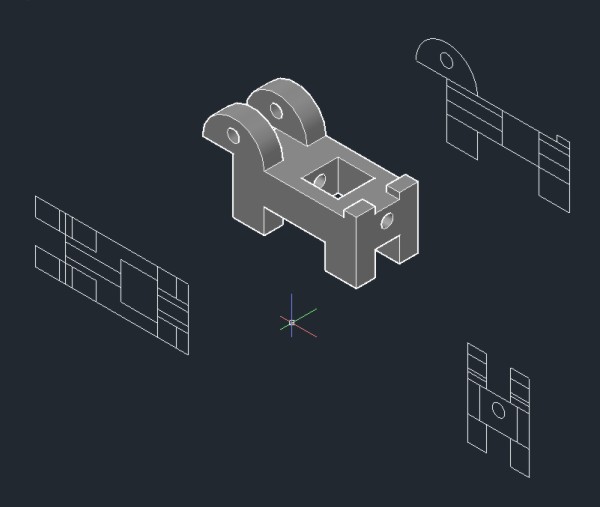
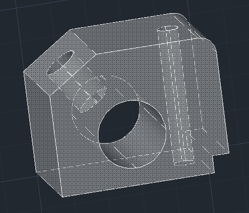
In AutoCAD, there are four types of 3D modeling. The first is wireframe modeling, where a three-dimensional structure is designed and used as a reference geometry on which various models and modifications are made.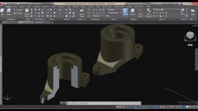 The second is the solid modeling where the user will be able to play with different masses. Surface modeling offers precise control of curved surfaces. Finally, mesh modeling allows the user to freely sculpt shapes, create folds and smoothing. The 3D models can be exported in .STL format, which allows them to be 3D printed.
There are 4 types of 3D modeling in AutoCAD
For those who are still in school, Autodesk also gives the option to purchase an educational version free for 3 years, which can be used on a maximum of two personal devices and is aimed primarily at students. In addition, the main versions allow all users to purchase a 30-day free trial period to discover all its functionalities. If by any chance you decide not to opt for this type of software, there are always alternatives, such as FreeCAD, Onshape or nanoCAD. In the following, we will explain the two main versions of AutoCAD, but it is important to mention that there is also a mobile version of the software.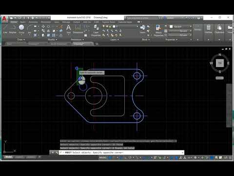
Full AutoCAD, the Most Complete Version
Of course, the full version of AutoCAD includes all the features of the limited version, plus many more. It integrates a palette of industry-specialized tools to reach multiple disciplines such as architecture, mechanical and electrical engineering. It allows 3D modeling, rendering and point clouds capable of generating final products that users will be impressed with. It also provides individual and network licensing, ideal for teams as it does not limit to one license situation per person. In addition, unlike the LT version, this extended version allows export in .stl files for 3D printing. The price of this version is $235 per month, although if you decide to pay annually, the price will be $1865 which in the end is a lower amount than if purchased monthly.
Full AutoCAD is the most complete version and allows 3D modeling functions (photo credits: Autodesk)
AutoCAD LT, the Cheaper, More Limited Version
This LT version of AutoCAD is much more affordable than the full version, so it is normal to wonder what the difference is. The reason is that AutoCAD LT does not have a Z-axis in the drawing, or anything that uses it. This means that it has no 3D modeling capability, it only allows editing in two dimensions. Even so, it allows multiple functions. One of the main advantages of the LT version is its ease of use. It looks and works just like the extended version, but without the clutter of 3D modeling operations, among others. It is therefore ideal for people who are just starting out in this area and are looking to understand the basic commands of the software. The price of this version is $60 per month, having the option to contract a full year for $460, a little cheaper than if purchased monthly.
In conclusion, it is important to remember that, at its inception, AutoCAD was not created as a software dedicated to 3D design. In addition, it has many complex tools that make it difficult to use. Therefore, as it is not a software for beginners, we recommend other simpler software to get started in the world of 3D modeling, such as TinkerCAD. If you already have knowledge in this type of software and you are thinking of getting it, you can find more information on the official AutoDesk website HERE.
Have you used AutoCAD to create 3D printable models? Let us know in a comment below or on our Facebook and Twitter pages! Don’t forget to sign up for our free weekly Newsletter, with all the latest news in 3D printing delivered straight to your inbox!
Fusion 360 vs. AutoCAD. Which application to choose for 3D printing?
There is no doubt that 3D printers can do a lot of great things. But to get the most out of them, you'll need a good CAD program to create your own 3D models. The two most popular options are Fusion360 and AutoCAD.
Now that you've narrowed down your choices to these two CAD packages, how do you know which one is right for you?
There is so much information to think about that it can be quite a difficult decision.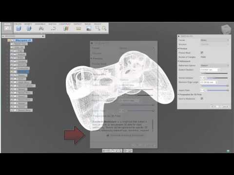 In this post, we will walk you through a detailed guide, taking a close look at the specifications, features, and differences of both apps to make your choice easier.
Which application is best for beginners?
Both Fusion 360 and AutoCAD are designed for people with at least some experience in 3D design, but that doesn't mean newbies should give up right away.
Fortunately, it won't take years to learn the usable design of both programs. Instead, you only need to understand a few basic terms and concepts to get started.
If 3D modeling software is still too complicated for you, you can always order 3D printing from 3D4U with pre-modeling of your project.
Comparison of Fusion360 and AutoCAD.
Both programs are similar in terms of functionality and user interface. However, they do have some clear differences. Below we have provided a table showing the differences between AutoCAD and Fusion360.
| Fusion360 | AutoCAD |
Designed for freeform models. | Emphasizes models based on geometry. |
| Works mainly with cloud technologies. | Works mainly with local and network files, but has the ability to save to the cloud. |
| It includes a lot of solid features and functions, but is a little more difficult to learn. | Fewer features, making it easier to learn. |
| Capable of creating incredibly detailed 3D models that are very well suited for 3D printing. | Can create both 2D and 3D drawings that will be primarily used in construction and engineering environments. |
| Ideal for modeling and prototyping products. | Suitable for developing detailed drawings and plans for manufacturing parts. |
| Mainly used by mechanical engineers, electrical engineers, and machining and manufacturing specialists. | It is mainly used by builders, engineers and architects. |
Cannot be controlled using the command line. | You can control it from the command line. |
What is the best CAD program and why?
Now that we know the difference in features and functions, we can begin to judge which CAD program is best for our needs as a 3D printer user and 3D model maker.
Whether you decide to buy a 3D printer for your home or a 3D printer for your business, you will need modeling skills to bring your ideas to life.
In the next section, we compared two applications in five different categories and determined a winner in each.
User support.
Both AutoCAD and Fusion360 are owned by Autodesk. So the customer support for both of these apps is very similar.
Fusion360 is mainly used by private users so you will probably find more questions and answers online than on AutoCAD, which is somewhat of an industry software.
Winner: Draw.
The complexity of the study.
Fusion360 includes many complex features that make it quite difficult to start learning, but most of the commands are intuitive.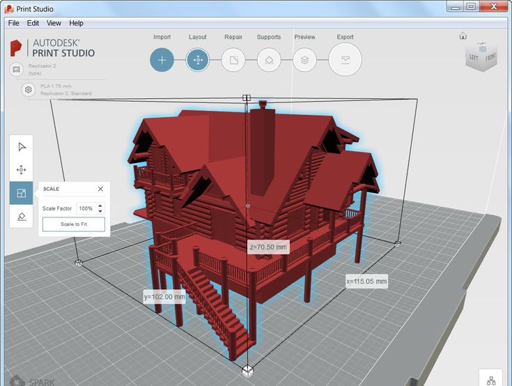
AutoCAD is much more limited and easier to learn and master.
Even though AutoCAD takes a lot of effort to learn, it's still generally easier than Fusion360.
AutoCAD has been around for a long time and there are many tutorials available on the Internet.
However, Fusion360 has a very large following and is probably the more popular option for hobby users, which means that with its huge community, the average person will easily find answers, tutorials, and tips for their project.
Winner: AutoCAD.
Possibilities.
Fusion360 and AutoCAD can create 3D models in virtually unlimited shapes and sizes.
However, Fusion360 has an advantage over AutoCAD in that it can create more complex designs, including:
- Application of materials to desired shapes;
- Inclusion in the development of the user interface of special design tools;
- Materials for stress testing in real conditions;
- Universal bolt hole tool;
- AI-based part design;
Winner: Fusion360.
User experience.
AutoCAD and Fusion360 are both user-friendly because both have intuitive option menus, well-designed icons, and an identical 3-axis (x, y, z) workspace.
The difference is that Fusion360 has a right-click context menu that improves your workflow and saves you time, while AutoCAD comes with the classic "command line".
Which is better is more of a personal preference.
The average private user of Fusion360 will feel more familiar.
Winner: Fusion360.
Simulation.
The clear winner here is Fusion360 as finite element stress modeling (FEM) cannot be done with AutoCAD.
When running this type of simulation, you will need to apply it to the material qualities of your 3D model. These material qualities include ductility, tensile strength, thermal resistance, and fracture strength.
With simulation models, you can measure the force required to fail, allowing you to refine your design in the virtual world before sending it to print.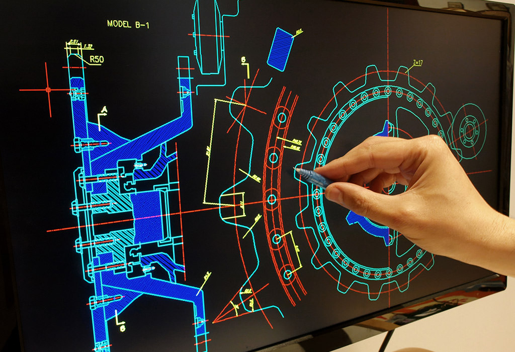
You can also stress analyze products with more than one ingredient. This allows you to assemble several parts together and determine the loads on the weakest link in the product.
After a thorough analysis of your project, all you have to do is choose and buy the right consumable for 3D printing.
Winner: Fusion360.
Rendering.
Rendering is great for seeing how your 3D print will look in real life.
Both Fusion360 and AutoCAD can efficiently realize and create amazing photorealistic images.
And since spectacle is an important factor in product development, you need to choose the 3D modeling software that will allow you to achieve your desired goal.
This is what you can achieve with AutoCAD and Fusion360, making them the perfect choice.
Winner: Draw.
Assemblies.
Assemblies allow you to connect multiple components together and connect them using common engineering links and mechanisms so you can see how your assembly will move in real life.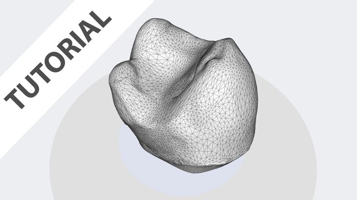
When it comes to assembly, the clear winner here is Fusion360. And this should come as no surprise, since most modern CAD programs blur the line between a real product and a virtual model.
This example is well illustrated when assigning constraints and relationships in 3D models.
For example, with Fusion360 you can model an internal combustion engine and put together all the components, such as pistons, connecting rod and crankshaft, just like in a real engine.
Therefore, you can see how the motor starts and rotates just like in the real world.
This feature is handy for checking that your custom builds will fit together and move as you expect before 3D printing them.
Winner: Fusion360.
Overall winner: Fusion360.
While AutoCAD is a popular and high quality 3D modeling software, Fusion360 is overall the best choice for those of us who use it to design 3D printed parts.
With Fusion360, you can create any 3D model efficiently and productively, whether it's a phone case, gaming miniatures or a drone.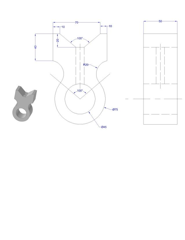
AutoCAD 3D modeling software overview.
AutoCAD specifications.
AutoCAD 3D modeling software is used to create both 2D and 3D models in the manufacturing industry and AEC - Architecture (architecture), Engineering (mechanical engineering) & Construction (construction).
AutoCAD Core Features:
Electrical toolset: AutoCAD integrates a standard electrical symbol library and simplified schematic diagramming. This feature is ideal for electricians and engineers.
Map 3D: AutoCAD 3D modeling software can easily read and edit GIS (Geographic Information System) topology for use in design, planning and geodata management.
Architectural toolset: this program includes specialized automatic tools that allow you to efficiently create architectural drawings and documentation. As a result, it is an ideal program for both architects and other architecture experts.
Mechanical toolset: although it is almost identical to the electric tool set, it is integrated with mechanical components and parts.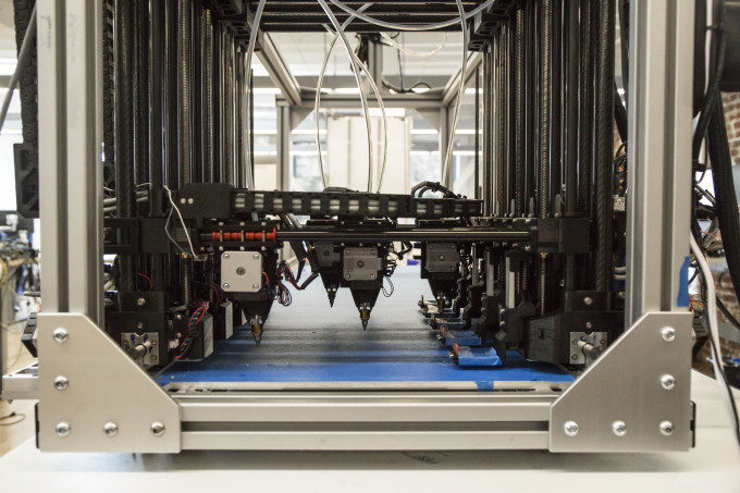 This function is most often used by mechanical specialists.
Plant 3D: This essential feature helps users create the diagrams and drawings needed for plant design.
AutoCAD system requirements.
| Operating system. | Windows 10 (64-bit only), Windows 8.1, or Microsoft® Windows® 7 SP1. |
| Memory. | 8 GB, but 16 GB recommended. |
| Processor type. | 2.5 GHz, but 3 GHz or more recommended). |
| Disk space. | 6.0 GB. |
| Video card. | 1 GB GPU with 29 GB/s bandwidth and DirectX 11 compatibility, but 4 GB GPU with 106 GB/s bandwidth and DirectX 11 compatibility is recommended.0026 |
Pros and cons of AutoCAD.
Pros.
- If necessary, you can add cloud storage to your subscription.
- has been the industry standard for decades.
- Although designed for 2D design, it can also perform 3D modeling.

- Excellent customer support and many online guides to help you in case of any problems.
- It does not need the cloud or the Internet to work properly, as it uses network and local files.
- This professional design software can be customized to suit your needs.
Cons.
- Proper use may take some time, especially if you are new to 3D modeling and drafting.
- This is primarily a 2D design program and focuses on that, not 3D.
- Computer requires more processing power than Fusion360.
- This is mainly a Windows program and although there is a Mac version, it has other features.
Fusion360 3D modeling software overview.
Fusion360 specifications.
Fusion360 cloud-based CAD software is commonly used in the manufacturing and AEC industries due to its many features. Some of the key features that make it popular include:
Cloud Software: This makes Fusion360 enable teams to work and collaborate in real time towards a common goal.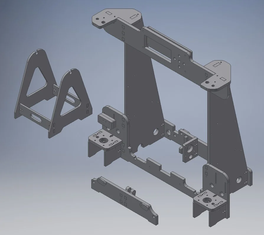 This makes it easy and quick to meet project deadlines.
Simulation: Fusion360 simulation software includes simulation features such as modal frequency, static stress, bending, and non-linear stress.
3D Modeling & Design: With Fusion360 you can perform parametric, mesh, surface and any other major modeling standard. You can also work with assemblies, which vary depending on the complexity of the project, or with independent components.
Data Management: With Fusion360 you can efficiently manage metadata and data related to projects and their files. In addition, all data about your files is stored securely in the cloud.
Rendering: Fusion360 can render photorealistically and detail both 2D documents and drafts.
Electronic versatility: With this 3D modeling software, you can work with various tools dedicated to PCB manufacturing and design.
Fusion360 system requirements.
| Operating system. | Windows 10 (64-bit only), Windows 8.1, or Microsoft® Windows® 7 SP1 Apple® macOS™ Sierra v10.12; Apple® macOS™ High Sierra v10.13; Apple® macOS™ Mojave v10.14. |
| Memory. | 3 GB RAM (4 GB or more recommended). |
| Processor. | 64-bit processor. |
| Disk space. | 2.5 GB. |
| Video card. | 512MB GDDR RAM or more, except for Intel GMA X3100 cards. |
Pros and Cons of Fusion360.
Pros.
- It uses the cloud, which means you can comfortably move your computer from one location to another without disrupting your workflow.
- It's easy and simple to learn and use, making it a great choice if you're new to this type of software. Therefore, you do not need to spend a lot of time learning how to use it correctly.
- Includes both organic and parametric modeling and provides you with a changelog.
- You can find many online courses and materials to hone your skills in using this 3D modeling software.
- It's very powerful and you don't have to design carefully to get exceptional quality 3D models.
Cons.
- Because it uses cloud technology, it cannot work without a fast internet connection.
- Sometimes when drawing complex 3D models, the process becomes slow.
- Your use of the cloud may affect your work if there are any issues or failures.
Conclusion.
Which is better between AutoCAD and Fusion360 is one of the most common questions we get asked about 3D modeling software. I hope this guide has helped answer any of your questions and made it easier for you to make your decision.
In most cases, Fusion360 is the best choice for 3D printer users. Fusion360 was designed to be a complete 3D design package and is virtually limitless in the possibilities of creating any shape you can imagine.
Our company uses Fusion360 in its 3D printing studio in Odessa. We always meet the needs of our customers and, when providing a 3D printing service, we optimize your project to minimize your costs while maintaining the quality and durability of the product.
3D printing: brief tips for moving from a CAD model to a printed object
Nadezhda
Whether it's just a hobby or a source of income, 3D printing is always based on product design. Those accustomed to traditional technologies will have to rethink the entire approach to product design and manufacture.
When the project is ready, a number of additional operations are performed: setting the orientation of the model and other parameters that ensure the proper printing process. In addition, it is necessary to take into account the fact that most 3D printers allow you to choose the degree of filling the model with cellular structures. The correct choice of this parameter provides protection of the object from deformation and destruction during the printing process, as well as significant savings in material and reduction in production time.
Finally, the last factor influencing the success or failure of the 3D printing process is the strength of the connection between the model and the table. If the workpiece is separated from the table during printing, then all the work will go down the drain.
Here, we'll walk you through the 3D printing process and provide some simple guidelines for using additive manufacturing in the design phase. In addition, we will dwell on the methods of preparing a finished project for printing, and also consider ways to securely fasten the workpiece to the table.
These recommendations apply primarily to Fused Deposition Printers (FDM) printers, but may apply to other types of printers. The process of obtaining a finished part by 3D printing is basically the same regardless of the method used.
Designing an object
Any 3D printing starts with construction. If you are developing a product yourself, then you need to build a 3D model of it in a computer-aided design (CAD) system to turn the designer's idea into reality. In this case, the object can be both very simple and very complex. However, too thin and too small models should be avoided.
Save the file in a special format for printing
To print an object, its model must be saved in a special file format - for example, STL, which has become the de facto standard in the world of 3D printing. In this format, model surfaces are represented as a grid of triangles. Simple surfaces are broken down into a small number of triangles. The more complex the surface, the more triangles you will need. Today, other formats are used in 3D printing, in particular, the 3MF format developed by Microsoft. But the most common is still STL.
CAD systems make it very easy to save the model in the desired format: just execute the command Save as . To improve print quality, it is desirable to set a number of settings for saving to the STL format - for example, the tolerance during transformation and the angle of the plane. The lower the conversion factor and the better the angle, the smoother the printed part will be.
Opening the file in the slicer program
Most, if not all, 3D printers come with their own slicer software. The slicer loads the STL file created in the CAD system and cuts it into layers, and then creates a control program for the printer.
Place the model correctly in the print space
After entering the print settings, the model (or several models) needs to be placed on the printer table. You can print many objects on one table at once. At the same time, compared to printing a single object, the time slightly increases, but in general it still turns out to be less. Here are some tips for choosing the right model orientation.
Set parameters
In the slicer program, the user sets parameters such as print speed, material consumption, nozzle and desktop temperatures. Most slicers have simple settings for beginners. In this case, most often there are also advanced settings so that experienced professionals can achieve optimal results. Advanced settings include percentage infill, amount of backing material, and type of backing or raft (this is a small, thin base that keeps the printed part stable. The backing is removed when it's finished). The number of options is truly endless. Specific settings vary depending on the brand of printer. It's easy enough to set them up.
Sending the control program to the printer
After specifying the print settings, the placement of future objects on the table, their orientation and quality, it's time to finally start the printer. Just press the button Print and find something to do while the production is in progress. Depending on the complexity of the design, the process takes from several minutes to several hours.
Finishing
Finishing includes the removal of the printed part from the table, as well as the removal of the support material by melting, mechanical separation or dissolution (depending on the design of the printer). The part may require some light sanding or polishing, but overall a properly printed object looks good from the start. Other types of finishing are placing plastic parts in a container with acetone to smooth out surface roughness, gluing (if the dimensions of the structure exceed the dimensions of the 3D printer or individual elements of the object must have different orientations), drilling holes and painting.
3D printing process
3D printer design considerations
Eliminate sharp corners
If the direction of the surfaces changes abruptly (for example, a vertical wall intersects with a horizontal floor), then this model is difficult to print. The printer will build excessive inner surfaces, wasting too much material. There are two easy ways to prevent this: add chamfers to smooth out where the surfaces meet, or round the corners so the printer gradually builds a vertical surface. In addition, rounding will increase strength, since destruction most often occurs at sharp corners.
Elimination of thin walls and small geometries
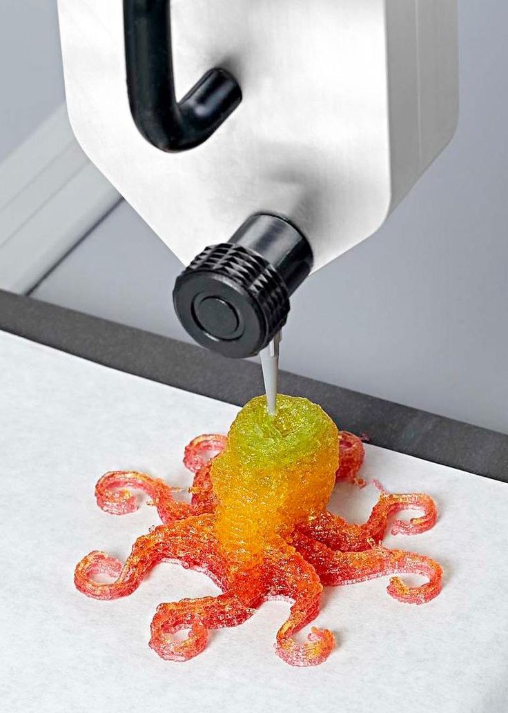
Fused fusion technology consists in feeding hot plastic through a nozzle to form the printed object layer by layer. The thickness of the extruded plastic layer cannot be made smaller than a certain limit, depending on the diameter of the nozzle and the speed of the print head. Excessively thin-walled details are difficult to print - often the result is a chaotic weave of fibers. If the part can be printed, it is very fragile and breaks easily.
Too thick walls - also bad
On the other hand, if the walls are too thick, they become brittle and crack easily. This is especially important when printing from materials other than resins, as excess thickness during the manufacturing process leads to internal stresses in the part. Even when printing from plastics, material is wasted on walls that are too thick and time is wasted.
Removing large overhangs
3D printers allow you to create amazing shapes and surfaces, but they are not capable of printing directly in the air.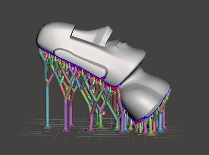 If there is a void in the part with material above it, additional support material must be used. Most slicers add material automatically, but require you to specify the orientation and volume of the support structure. Printers with a single nozzle create an array of thin columns, which then have to be broken off. The result is an uneven surface. Therefore, it is recommended to avoid large overhanging elements whenever possible in order to reduce the need for support material.
If such an element is unavoidable, you can try to flip the object. Most printers are capable of printing overhanging elements with an angle of about 45 degrees. At a certain height, the edge of such an element may sag somewhat. The actual capabilities of a particular printer are determined by trial and error.
Holes shrink
Remember that the part is made of heated plastic. As it cools, it inevitably shrinks. Therefore, holes and other critical structural elements have to be made larger so that after shrinkage their size is as close as possible to the required one.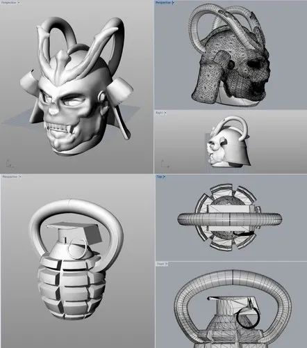
However, if a tight tolerance hole needs to be made, it is best to print it to a smaller diameter and then ream it with a suitable tool. This is especially true for holes whose axis is parallel to the printer table.
Increasing the footprint
If the area of contact between the object and the base is small, the part may separate from the table during printing. To prevent this from happening, wide bases are added to the model legs, which are installed on the printer table. In general, the closer to the table, the more material must be added to the support. There are other ways to securely fasten the part to the table, which we will discuss a little later.
Special moves
The right approach to design makes printing easier. In addition, there are special post-processing techniques that are important to be aware of.
Place round surfaces vertically
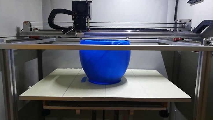
The model should be oriented so that the minimum amount of support material is used.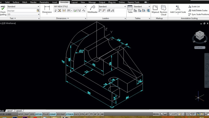 Ideally, it should rest on the table with a large flat edge. In addition, circular geometry must be placed so that the circular faces are vertical. If we look at the printer table from above, we should see a round silhouette of the object. In this case, the part comes out as symmetrical as possible with the formation of a solid round structure.
Place voids and holes vertically
If there are voids in the model (for example, it is a rectangular pipe), it is desirable to place such voids vertically in order to reduce the amount of support material. If you print the pipe in a horizontal position, you will have to provide support for the entire inside. If you put the pipe on the end, then no support is required at all.
This is true for holes too: to get a hole with a straight axis, it is best to print it vertically - in the form of a stack of rings, which avoids warping or deforming a round hole into an oval one.
Set print quality settings
Proper selection of print parameters, such as STL conversion tolerance and slicer software settings, allows parts to be produced with surface quality that matches that of cutting. However, this entails an increase in print time. When choosing quality parameters, one should proceed from the purpose of the object: is it a finished product or a prototype? Will the part be visible or hidden?
The quality parameters also affect the shape of the holes in the part. In CAD files, holes are represented as a set of straight lines at an angle to each other. The higher the quality of the model in the saved STL file, the less the circle looks like a polygon.
Reducing the layer thickness
To obtain the best quality, especially when using layered deposition technology, it is necessary to reduce the thickness of the layers. It does increase the print time, but the end result is worth it!
Optimizing the filling with honeycomb structures
Objects do not have to be solid from a strength point of view. Similar to a honeycomb, printers can create a honeycomb infill that balances strength and saves expensive polymer material. However, if the printed part serves as a prototype for strength testing, and the serial product will be manufactured by traditional methods, and also if the part is subjected to certain types of mechanical stresses and pressures, a solid design will be preferable.
Choosing material
Printing success depends to a large extent on the correct choice of material. Materials have different properties. For example, the melting point of thermoplastic polyurethane (TPU) and polylactic acid (PLA) is lower than that of acrylonitrile butadiene styrene (ABS). In addition, the material is taken into account when choosing the type of support structures. For an object made of polylactic acid, supporting elements can be made from the same polylactic acid, since it will be quite easy to separate them from the finished part. If the part is printed from ABS plastic, then the support elements must be made from a different material, and it is better not to use such elements at all in thermoplastic polyurethane parts.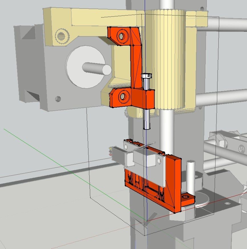
Cellular filling
A solid body is not always the best choice for 3D printing. Printing solid parts has its advantages, but the internal honeycomb structure saves both expensive material and time.
Creation of objects with a given degree of filling with cellular structures is a unique possibility of three-dimensional printing. Moreover, it is not required to design such a structure: this is done by the slicer program. As a rule, it is enough to set only the percentage of filling (the closer it is to 100, the more solid the object will turn out) and select the type of cells, if the printer has such an opportunity.
In addition to saving time and material, the internal honeycomb structure has many other advantages.
Cellular filling prevents warping
Printing large objects in one piece causes warpage hazard. By reducing the infill percentage, the air during printing passes through the part, providing more uniform cooling and eliminating warpage.
Cellular filling does not lead to loss of strength
Printing cells instead of solid material does not reduce the strength of the part. In many cases, a honeycomb part is strong enough for the chosen application, but lighter and less material intensive.
The function determines the selection of cell geometry
Most slicers support a wide variety of cell geometries. The optimal option is determined by the functional purpose of the object. Standard box padding simplifies printing, while hexagonal and triangular boxes add strength. Wave fill allows the object to bend or twist.
How do I choose the right filling percentage?
In general, the strength of an object increases as the infill percentage increases. Most printers have a default infill percentage of 20, which is optimal in some cases but too high or too low in others. Consider mechanical stresses in the printed object and increase the percentage of infill in areas where greater strength is required. If high strength is not required, choose the lowest possible filling. This saves material and speeds up printing. Most often, the selection of the optimal percentage of filling is done by trial and error.
Ways of fastening the workpiece to the table
"Rafts", "brims", "skirts" - these terms sound funny, but they just refer to the three main ways of attaching a 3D printed part to a printer table. Let's take a look at each of these methods and their areas of application.
Skirt
The skirt involves creating a few rings around the object at the beginning of the print to make sure the plastic extrudes normally. The skirt is not in contact with the object at all. It surrounds the printable area and helps start the fusing process. When creating a skirt, a large volume of hot thermoplastic polymer passes through the nozzle. This prepares the printer for printing the part itself. This guarantees good adhesion to the table and obtaining smooth surfaces of the object.
Brim
The brim is a wide flat area connected to the main object as a support base (think of a brim of a hat). It is very similar to a skirt, but connected to the model. In addition to all the advantages of a skirt, the brim keeps the edges of the object being made on the table.
When printing, the outside of an object often cools faster than the middle, causing the edges to curl. Brim prevents this phenomenon by holding the edges.
Raft
The raft is a detachable base designed as a thin mesh platform that sits under the entire object (which rests on the raft). To create a raft, the printer first prints a flat plate in two or three layers, and then begins to manufacture the object.
Rafts provide excellent adhesion to the table surface and also serve as a strong base for printing. This is especially useful when making small and oddly shaped parts that do not fit well on the table, as well as thin-walled objects.
After printing is completed, in most cases the raft will separate easily from the part.
If the printer does not have a heated desktop function
Rafts are used if the printer does not have a desktop heater. In this case, excessive adhesion becomes a problem.
An alternative method is to apply adhesive paper tape to the printer bed, wrapping the edges down if possible (this also protects the bed). You can also use packing tape, but it is usually more expensive.
If buckling does occur, or if the object separates from the table, apply soluble glue stick to the adhesive tape. This will enhance adhesion.
Find out the features of a specific 3D printer and take them into account when preparing your model
Three-dimensional printing is not only a science, but also an art. Effective design for subsequent 3D printing requires an understanding of the technological process, taking into account its features and the purpose of the future object.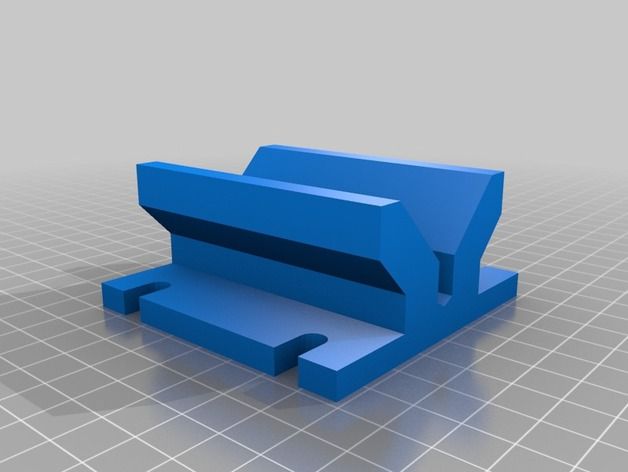 This will greatly improve print performance.
Use of Solid Edge in 3D printing
Not all CAD systems are suitable for 3D printing
The capabilities of the applied system should not limit designers. Our Solid Edge® system is designed with the latest 3D printing technologies in mind. Various 3D printers and 3D printing services are supported.
Take it to the next level with specific techniques for designing 3D printed parts
Generative modeling in Solid Edge opens up new possibilities: the designer selects a specific material, sets the design space, allowable loads, restrictions and target mass of the part, and the system automatically calculates the desired geometry. As a result, 3D printing methods can produce the most complex shapes.
In addition, when building models, the use of the results of three-dimensional scanning is provided. Solid Edge successfully combines the traditional boundary representation of solid models (B-Rep) and the representation of surfaces in the form of a grid of triangles, which avoids time-consuming transformations that are fraught with errors.
If you've already downloaded an STL file for printing, our unique synchronous technology makes it quick and easy to edit imported models in Solid Edge in preparation for the process.
Print with your own printer or submit an order to a 3D printing service provider
Printing in Solid Edge on a local 3D printer is done with the command 3 D print . Models can be saved in STL and 3MF formats, or sent directly to Microsoft 3D Builder. If you don't have your own 3D printer or need to try out different materials and surface finishes, Solid Edge allows you to directly submit your models to cloud-based 3D printing services (such as 3YOURMIND). You immediately receive quotes for the production of parts from various materials with its subsequent delivery directly to your door.