3D printer xyz axis
How to Calibrate Your Z-Axis on Your 3D Printer – Ender 3 & More – 3D Printerly
3D Print Filament | Guides
ByMichael Dwamena Reading Time: 8 minutes
Calibrating the Z-axis on your 3D printer is a good way to ensure you are getting dimensionally accurate 3D printers, as well as creating better quality models. This article will take you through the calibration process for your Z-axis.
To calibrate the Z-axis on your 3D printer, download and 3D print an XYZ calibration cube and measure the Z-axis with a pair of digital calipers. If it doesn’t have the correct measurement, adjust the Z-steps until the measurement is correct. You can also calibrate your Z offset using a BLTouch or by ‘live-leveling’.
There’s more information that you’ll want to know for calibrating your Z-axis, so keep on reading for more.
Note: Before you start calibrating your Z-axis, you have to make sure your printer is in order. Here are a few ways to do this.
- Make sure all the belts are properly tensioned
- Check and see if the print bed is leveled
- Make sure your Z-axis isn’t slipping or experiencing binding
- Calibrate your extruder e-steps
How to Calibrate Z Axis Steps on a 3D Printer (Ender 3)
An XYZ Calibration Cube is a model with precise dimensions you can print to know if your printer is correctly calibrated. It helps you see the number of steps your motor takes per mm of filament it prints in all directions.
You can compare the expected dimensions of the cube with its actual measurements to know if there is any dimensional deviation.
You can then calculate the proper Z-steps/mm for your printer with these values. Check out the video below to see how you can calibrate your 3D printer’s stepper motors.
Step 1: Get Your Printer’s Current Z-Steps/mm
- If you have an Ender 3 or similar printer running the Marlin firmware, you can get it directly via the display on the machine.
- Navigate to Control> Motion > Z-Steps/mm. Note down the value that is there.
- If your printer doesn’t have a display interface, you can still get the Z-Steps/mm, but with a more complex method.
- Using control software like Pronterface, send the G-Code command M503 to your printer – it requires some setup to get started.
- It will return some lines of code. Look for the line that starts with echo M92.
- Look for the value starting with Z. This is the Z-steps/mm.
Step 2: Print the Calibration Cube
- The Calibration Cube’s dimension is 20 x 20 x 20mm. You can download the XYZ Calibration Cube from Thingiverse.
- When printing the Calibration Cube, don’t use a raft or a brim
- For the best results, slow down the print speed to around 30mm/s and reduce the layer height to around 0.16mm.
- When the cube finishes printing, remove it from the bed.
Step 3: Measure the Cube
- Using a pair of Digital Calipers (Amazon), measure the Z-Height of the cube.
- Measure it from top to bottom and note the measured value down.
Step 5: Calculate the New Z Steps/mm.
- To calculate the new Z-Steps/mm, we use the formula:
(Actual Dimension ÷ Measured Dimension) x Old Z Steps/mm
- For example, we know that the cube’s Actual Dimension is 20mm. Let’s say the printed cube, when measured turns out to be 20.56mm, and the old Z steps/mm is 400.
- The new Z-steps/mm will be: (20 ÷ 20.56) x 400 = 389.1
Step 6: Set the Accurate Value as the Printer’s New Z-Steps.
- Using the printer’s control interface go to Control > Motion > Z-steps/mm. Click on Z-steps/mm and input the new value there.
- Or, using the computer interface, send this G-Code command M92 Z [Insert accurate Z-steps/mm value here].
Step 7: Save the New Z-Steps Value to the Printer’s Memory.
- On the 3D printer’s interface, go to Configuration/ Control > Store memory/settings. Then, click on Store memory/settings and save the new value to the computer memory.
- Using G-Code, send the M500 command to the printer. Using this, the new value saves to the printer’s memory.
How Do You Calibrate Z Offset or Z Height on a 3D Printer
If you do not have a BLTouch, you can still calibrate your printer’s Z offset with a bit of trial and error. All you have to do is print a test print and make adjustments based on the quality of the print’s infill in the middle.
Here’s how you can do this.
Step 1: Make Sure Your Print Bed is Leveled Correctly and Clean.
Step 2: Prepare the Model for Printing
- Download the Z Offset Calibration Model by scrolling down to the ‘Model files’ STL section – there is a 50mm, 75mm & 100mm square option
- You can start with 50mm and decide to move up if you need more time for making adjustments.
- Import it to your chosen slicer and slice the file
- Save the file to an SD card and load it onto your 3D printer
- Begin printing the model
Step 3: Evaluate the Model as it Prints
- Check the infill of the model and how it’s extruding to determine the adjustments that need to be made.
- The objective of this print is to get the first layer as smooth and level as possible.
- If the gaps in the infill are significant and there are low spots between them, reduce your Z offset.
- If the lines in the print are smooshed together and do not retain their shape, increase your Z offset.
- You can change the Z offset in intervals of 0.2mm until you reach the desired change – do keep in mind that the adjustments to the Z offset can take a few extruded lines to show its effects.
Once the top layer is smooth without any smooshing, gaps, valleys, or ridges, you’ve got the perfect Z offset for your printer.
How To Calibrate Your Z-axis Using a BLTouch Probe
The Z offset is the Z distance from the printer’s home position to the print bed. In a perfect world, this distance should be set to zero.
However, due to inaccuracies in the print setup and the addition of components like a new print surface, you might have to adjust this value. The Z offset helps compensate for the height of these objects.
A BLTouch is an automatic leveling system for your print bed. It can help measure the exact distance from your nozzle to your bed and help compensate for any inaccuracies using the Z offset.
The video below takes you through the process of calibrating your Z offset on an Ender 3 V2 with a BLTouch. V3.1 (Amazon).
Let’s see how you can do this.
Step 1: Heat the Build Plate
- If your printer runs the Marlin firmware, navigate to Control > Temperature> Bed Temperature.
- Set the temperature to 65°C.
- Wait for about 6 minutes for the printer to reach this temperature.
Step 2: Auto-Home Your Printer
- On your control interface, click Prepare/ Motion > Auto-home.
- If you’re using G-Code, you can send the command G28 to your printer to auto-home it.
- The BLTouch will scan the print bed and try and determine where Z = 0
Step 3: Find the Z Offset
- The BLTouch will be at a distance of about Z = 5mm from the printer’s bed.
- The Z offset is the distance from where the nozzle is currently to the print bed. To find it, you’ll need a piece of paper (a sticky note should do just fine).
- Place the piece of paper under the nozzle
- On your printer’s interface, go to Motion > Move axis > Move Z > Move 0.
 1mm.
1mm. - On some models, this is under Prepare > Move > Move Z
- Gradually reduce the Z value by turning the knob counter-clockwise. Turn the Z value down until the nozzle grips the paper.
- You should be able to pull the paper out from under the nozzle with some resistance. This Z value is the Z offset.
- Note down the Z value
Step 4: Set the Z Offset
- After finding the value for the Z offset you may need to input it into the printer. In some cases, it will automatically save.
- ON newer models, go to Prepare > Z offset and input the value you’ve gotten there.
- On older models, you can go to the Main screen > Configuration > Probe Z offset and input the value.
- If you’re using G-Code, you can use the command G92 Z [input the value here].
- Note: The square brackets in front of the Z offset is very important.
 Don’t leave it out.
Step 5: Save the Z Offset to the Printer’s Memory
- It’s important to save the Z offset to avoid resetting the value when you turn off the printer.
- On older models, go to Main > Configurations > Store Settings.
- You can also end the G-Code command M500.
Step 6: Re-Level the Bed
- You want to manually re-level the bed one last time so that all the four corners are at the same height physically
Well, we’ve reached the end of the article! You can use the methods above to configure your 3D printer Z-axis so you can get accurate prints consistently.
Just make sure other parts of your printer, like the extruder’s flow rate, are in proper order before making these adjustments. Good Luck!
Similar Posts
3D Print Filament | 3D Printer General
Resin vs Filament 3D Printers (SLA, FDM) – Which Should I Buy?
ByMichael Dwamena Reading Time: 15 minutes
In the highly advanced world that we live in today, 3D printers and their developments have become diverse. People today are faced with several options to consider when it comes to features, functionality, filament compatibility, mode of technology used, and whatnot. This article will aim to look into SLA & FDM 3D printing and help…
Read More Resin vs Filament 3D Printers (SLA, FDM) – Which Should I Buy?Continue
3D Printer – X,Y and Z Axis Calibration – www.muckypaws.com
A common mistake when calibrating your printers X, Y and Z Axis is to print a 20mm calibration cube from Thingiverse, measure the dimensions with Callipers and make adjustments to your step rates.
I too was simply following instructions… Whilst that method may appear to work and it did print a perfect 20mm cube, it doesn’t take into account the materials expansion/contraction ratio.
I’m informed by the professionals the correct method is to measure the actual head movement and calculate your steps accordingly.
Achieving this is straight forward. Make sure your printhead has cooled down and attach a pencil.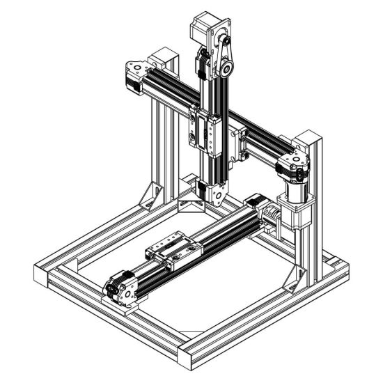 I used an elastic band, though you may need to get creative with your printer. Clip a piece of paper to the print bed and enter your printers Axis movement menu.
From the printer menu, I requested an X Movement of +100mm and a Y Movement of +100mm.
Using digital callipers, measure the actual distance travelled by the print head.
For the Z-Axis, I measured the current height from the bed to a fixed point underneath the print head before zeroing the callipers then requesting a movement of +100mm taking the same measurement. Though you can clip paper to the frame and move the pencil to the Z Axis and record movement that way.
To calculate your eSteps, the equation is simple,
(Amount Requested / Actual Amount) X Current Steps Value = New Steps Value
How to calculate New Steps ValueFor example, if I requested 100mm on the X-Axis and the printer moved 98.5mm then the calculation would be (100/98. 5) x 80.12 = 81.34, therefore you would enter 81.34 in your printers X-Steps set up.
Repeat the exercise again until your printer is moving the required distance.
And that’s pretty much all there is too it!
Clip Paper to the Print Bed and Attach a Pencil. Current Steps Configuration Screen Final Calibration, Spot on! Print an X, Y, Z Calibration CubeLike this:
Like Loading...
3D Printing, Personal, Tech
3D Print, Calibration, Geeetech, How To, XYZ
Translate
Search for...
Follow www.muckypaws.com on WordPress.com
Follow Blog via Email
Enter your email address to follow this blog and receive notifications of new posts by email.
Email Address:
Advertisements
Categories
CategoriesSelect Category3D Printing65028BitairlinesAlgarveAmstradAntiguaAppleAppsArcadeAustraliabad customer serviceBakingBereavementBratislavaBudapestCairoCambridgeCancerCaribbeanCelebrationscinemaComponentsComputers and InternetCopenhagenCustomer SatisfactionCustomer ServiceDallasDatingDiabetesDIYDominican RepublicEducationEgyptEuroMillionsFlightAwareFranceFreeFreewareGameBoyGames ConsoleGamingGDPRGermanyGreaseWeazleGriefHackingHATHong KongHospitalHowToIbizaIndiaInterviewiOSItalyJapanKangaroo IslandLondonLotteryMacMac OSXMacOSMadridManic MinerMedicalMiscellaneousModsNHSNintendoobservationOctoPrintOSXParisPCPC SoftwarePersonalPhotographyPhotoshopPiPiHolePortugalPragueProjectsPuzzleRamblingsrantRaspberry PiRecipesRepairsRetroRetro GamesRetropieRomeScamSecuritySilverstoneSingaporeSlovakiaSmith and BrooksSmithAndBrooksSoftwareSpainSTLTeam OutingsTechTouristTravelUKUK LotteryUncategorizedUnityUSAViennaWembleyWidowedWindowsXCodeXmasYouTubeZX SpectrumWe go down - we grow up, or the Z axis for cheap / Sudo Null IT News
Good day to you, dear geeks and sympathizers! This publication is a continuation of the description of the design of my homemade 3D printer. The Z axis is one of the most controversial printer nodes. What to choose - the ultimate accuracy or good scaling? Move the x-axis or the printer's desktop? Two approaches, two solutions.
I couldn’t look at the first 3D printers without shuddering: the designs were immature, many components were used in violation of specifications, because of the general fluctuation, constant adjustments, minor repairs were required, the size of the working field was small. I decide to solve the problem of internal contradictions by simply crossing hedgehog with a snake portal milling machine and 3D printer designs.
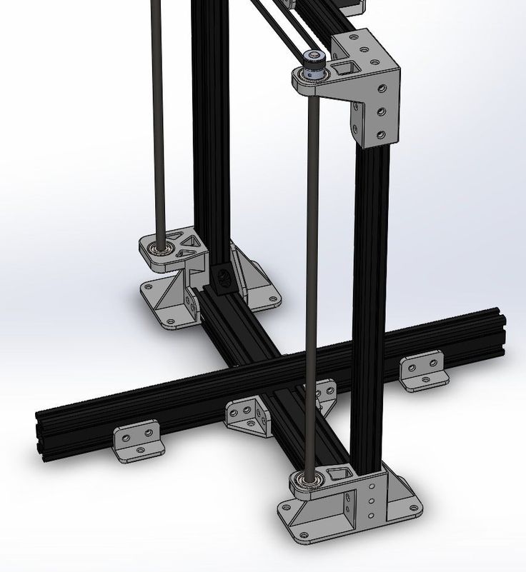
The skeleton of a 3D monster was designed and twisted together:
It consists of forty-millimeter aluminum structural profiles connected by thick 45x45 corners and M8 bolts. This design has dimensions of 60x40x40 cm and is absolutely unshakable during normal operation of the printer. The size of the working platform was 45x22 cm, with a maximum height of 28 cm. The carriages are driven by precision trapezoidal screws mounted on angular contact bearings. Each screw is driven by a stepper motor via a 3:1 belt drive. The upper ends of the screws are turned and inserted into needle bushings so that the axial displacement of the screw in the bushing prevents it from wedging during thermal expansion. I used a polymer nut for the screws: there are no high speeds / loads, and the polymer nut is not so demanding on lubrication and is much easier to install. In this design, the height of the model is provided by raising the X-axis above the table, and the Z-axis is used as a movable support for the X-axis.
Operation video:
This axle worked without any problems until this printer was taken apart for parts.
Disadvantages of this solution:
1. Price. Precision components are expensive.
2. Design complexity
3. Poor scalability.
When I began to build the second printer, experience and stinginess were involved in the creation of the design along with an innate desire to go my own way, not expecting favors from nature.
Accordingly, the new printer had to become not only simpler, faster, more versatile, reliable and maintainable, but also much cheaper.
Instead of a screw drive, the Z-axis of the new printer was chosen, but a cable structure similar to a crane winch. It consists of the actual drive mechanism with a belt reduction gear and two blocks on which the entire mass lies along the Z axis.
Here is a photo of the printer as a whole: paired plain bearings made of sintered bronze.
In the next two videos you can see the design of the winch, there is nothing complicated:
Z-axis skeleton: simple and lightweight design.
Power calculations: The drive drum has a radius of 10 mm. Accordingly, a torque of 0.3 Nm (normal Nema 17 motor) on a 10 mm lever will be 30 N. A belt gearbox with a gear ratio of 2: 1 doubles this number.
As a result, the maximum force that this winch can develop is about 60 Newtons, respectively, the maximum mass of the Z axis, together with the masses of the table and the object, should not exceed 6 kg at rest.
Now let's determine the losses for acceleration and deceleration of the Z axis: to accelerate 1kg of mass with an acceleration of 1m/s², it is necessary to apply a force of 1 Newton. In fact, an acceleration of 1 m / s² for the Z axis is quite enough, and each accelerated kilogram will cost us 1 N of applied force.
The heaviest element in the design is the heated table, it is a duralumin plate 350x350x3 mm, weighing 980 grams with glued heating elements with a total weight of 150 grams.
The rest of the structure, including Basotect thermal insulation, weighs approx.00 grams.
The total weight of the structure is about 2030 grams, which, when rounded up, will require 21 N for holding and another 2.1 N for acceleration. In total, once again rounding up, 24 N.
If we add a kilogram model to the mass of the Z axis, then 34 N will be needed, which is
slightly more than half of the rated winch power. It would seem that the design is redundant in terms of power. But the devil, as always, is in the details. The fact is that in order to achieve maximum torque, maximum currents must flow through the motor windings, which will inevitably cause it to overheat and prematurely fail.
For this reason, I designed the structure with a large power margin, and experimentally set the motor current a little more than the minimum required. At the same time, the motor heated up to 50-60 ° C, which is quite acceptable according to specifications.
In this video, the winch easily juggles the Z axis without a working table, but with two filament spools weighing 1300 grams:
So, the power issue is resolved. Now let's talk about accuracy. Given the parameters of the winch and motor components, with 1/16 microstepping, it is possible to move the Z axis in 0.02 mm increments. Now consider the problem of accuracy in a winch with a single-layer winding of the cable. The radius of the drive drum in my design is 10 mm, respectively, the circumference when winding will be 62. 8 mm. It takes about seven turns to raise the Z-axis by 44 cm. When using a cable with a thickness of 1 mm, the axial displacement of the winding will be 7 mm. In this case, there is a change in the distance from the point of contact of the cable with the drum to the lower support block.
Let's calculate how bad everything is: the drive drum is in the center of one of the diagonals of the square formed by the bottom of the printer body. Accordingly, the drum is removed from each of the lower support blocks by 320 mm. By simple calculations, it turns out that when the table is moved by 440 mm, the drive geometry will change by 0.077 mm.
Quality trapezoidal threaded screws provide 0.07 to 0.4 mm accuracy at these distances. Simply put, they do not provide any meaningful gain in accuracy. If for some reason you need to print models with a height greater than 44 cm, you just need to proportionally increase the diameter of the drive drum (to keep the number of revolutions required to move the axis) and the gear ratio (to maintain the nominal load on the motor). At the same time, the cost of the mechanism increases slightly, in contrast to the design with a screw drive.
One of the test objects:
In conclusion, I can say that although experience is a derivative of the difficulties overcome and mistakes made, sometimes the process of acquiring it is more enjoyable than the results achieved.
There will be no 3D models because I can't find them on disk.
Published under the WTFPL license.
And traditional: Have fun!
Printer calibration and ... | BeyondWiki
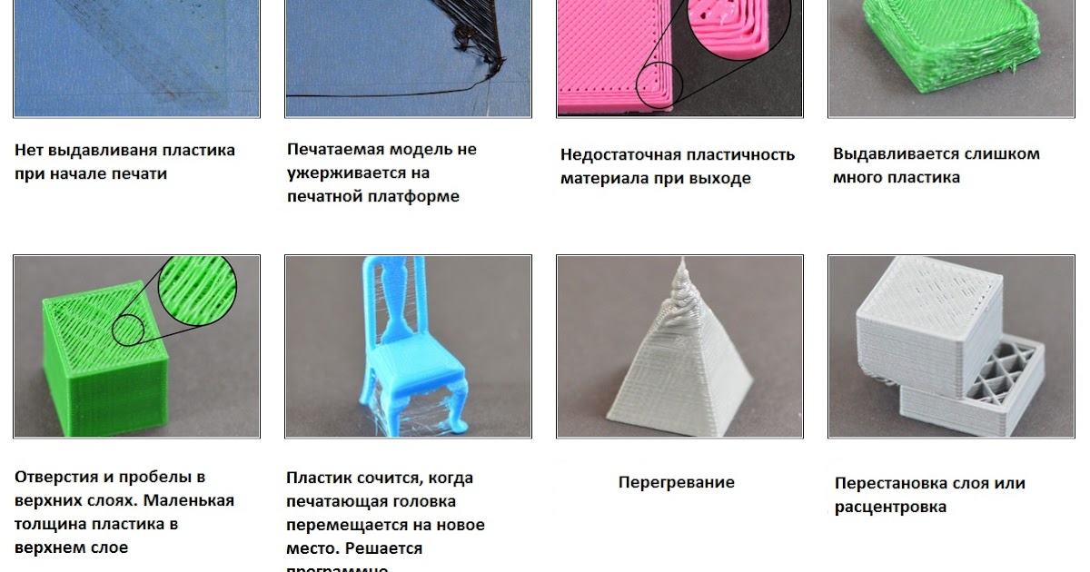
In past 3D printing articles, we've looked at different types of 3D printers, FDM printer components, plastic types, why printing problems occur and how to fix them. This article is about how to prepare the printer for the first print or how to start 3D printing after a long period of inactivity.
Until now, 3D printers are quite complex, “incomprehensible machines” that require careful attention and a clear understanding of the device of the printer itself. Unfortunately, at the moment you can't start 3D printing by simply buying a 3D printer, placing it on a surface and pressing the start button - you first need to learn the settings and prepare the machine for printing.
NOTE
Most modern 3D printer manufacturers have their own software to operate the device. Therefore, each operation described in this manual is performed differently on different printers: somewhere through the firmware, and somewhere manually.
Before you start working with the printer, you need to prepare a space for it: the 3D printer must be installed on a clean, non-flammable surface in a draft-free room; also the plane (for example, a table) where the printer will be installed must be level and stable. Once you have found a suitable location for your 3D printer, you can start setting it up.
Calibration
IMPORTANT
For each printer, calibration can be done in different ways. First you need to check the user manual.
Calibration is an essential part of a 3D printer. First of all, it is necessary to calibrate the Z-axis: usually the Z-axis is regulated from two sides by two stepper motors on steel studs. It happens that due to transportation, manual assembly of the printer or careless use, the left side of the axis is higher or lower than the right side. As a result, the X-axis, which is held on the Z-axis, moves, becoming not parallel to the plane of the table.
To solve this problem:
- Calibrate the Z-axis using the printer's built-in calibrator: for example, this function is available on Prusa printers.
- Perform manual calibration by lifting the Z-axis up to the stop.
printer Z-axis raised to the stop Once the Z-axis is calibrated, it is necessary to check the belt tension on the X and Y axes. To do this, move the extruder and table to the middle of their axes, and then press the belt with your finger from above and below: When pressed, the belt should show little resistance. It is worth noting that both insufficient and excessive tension can lead to printing problems - in this case, the belts should be tightened. It is also important to check if the leading axles of each axle are sufficiently lubricated.
The last thing to do is to calibrate the extruder - often referred to as “z offset calibration”. To do this, you need to set the calibration parameter so that a sheet of paper passes through the gap between the table and the extruder. At the same time, the sheet should not move too freely or even be sandwiched between the surfaces.
hot", with a heated table to at least 60-80 degrees. The temperature can reach up to 100 degrees if plastics are printed, which require a high temperature for heating the table surface.
Important, if on a 3D printer the height of the table is adjusted in 4 points, then you must first perform this calibration in the middle of the table, changing the “z offset” parameter. Next, the calibration is carried out along the edges, already changing the height of the table, until a sheet of office paper passes into the gap between the table and the extruder in the same way.
Preparing the table and plastic
After all the manipulations with the printer axes, table height and extruder, you can load plastic into the extruder. Before doing this, you need to check that:
- plastic free from dust and dirt
- plastic thread is not deformed
- plastic not brittle
- plastic tip cut at an angle
- extruder heated to the melting temperature of plastic
After that, you can load the plastic into the extruder and then wait until the plastic of the corresponding color begins to extrude from the extruder.
The next step is to prepare the table surface for printing. The guide "Types of Plastics, Their Features and Applications" tells about the different coatings for certain plastics.
There are different algorithms of action for different coatings that improve the adhesion of the material to the surface. In the case of PEI and magnetic coating, it is often enough to wipe the surface with alcohol (Isopropyl alcohol is preferable, but ethyl alcohol is also suitable). If the printer table is covered with glass or a mirror, then it can be treated with adhesive spray or paper glue. It is recommended to cover the table with blue masking tape, which has better adhesive properties than a smooth table.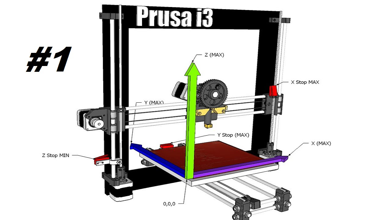 And then, if necessary, treat the print area with an adhesive.
Printer Masking Tape When printing with ABS plastic, you need to apply glue stick for paper on the table, for TPU you need to cover the table with a thin layer of talcum powder, and when printing RUBBER, you must definitely stick transparent tape on the table. Also, after every 3-5 printing sessions, it is required to wipe the surface of the table with alcohol.
Seal
Once the printer has been prepared, the first print can be made. However, it is too early to print the desired models - first you need to print a test cube to evaluate the quality of the print. The model of the cube can be any, but most often it is a cube of 20x20x10 mm or 20x20x20 mm. The printed cube should be even and neat. It is also important to measure the size of the cube with a caliper in order to evaluate the print error.