3D printer steps per mm
How To Calibrate Your 3D Printer's Extruder
This quick and informative guide will help you calibrate your extruder perfectly, resulting in accurate, quality prints.
Taylor Landry
September 19, 2022
Your 3D printer extrudes and retracts precise amounts of filaments in order to create your printed masterpieces. Well, it does if it’s properly calibrated. Calibrating your extruder is one of the most important, as well as one of the most overlooked, things you can do to your machine.
If you’ve been unhappy with your printing results or have noticed either under or over-extrusion, this calibration will help resolve some or all of these issues.
Before we begin, let’s identify the components on your printer that we’ll be covering, as well as the 2 different types of extruder setups.
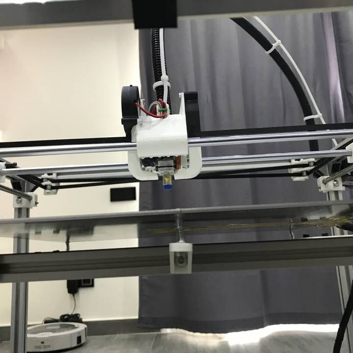
Direct vs. Bowden ExtruderDirect extruders are mounted directly onto the hotend. They are the most common type of extruder on Cartesian-style printers.
This is a picture of the Lulzbot Taz Mini Wade’s style direct extruder and hot end assembly.
Bowden extruders are not mounted directly on the extruder. Instead, they are typically mounted on the body of the printer in a stationary position. They are connected to the hot end with a PTFE, or other similar low-friction tubing. Bowden extruders are most commonly found on delta style printers like the Rostock Max v2 by SeeMeCNC and the KosselPro by OpenBeam.
This is a picture of the SeeMeCNC Rostock Max v2 which uses a Bowden extruder:
Direct and Bowden extruders are very different, but calibration is similar for both.
Bowden Extruder Calibration:
-
Connect your printer to MatterControl. Ensure hot end and heated bed (if applicable) are turned off and cool to the touch.
-
Remove Bowden tube from the hot end side. Leave it attached on extruder side.
-
Feed filament (any filament except flexible filaments like Ninjaflex) through your extruder until it just starts to come out of the Bowden tube.

-
Using a razor blade or sharp scissors, cut the filament flush/square with the Bowden tube. You want a nice, flat cut so that it’s more easily measurable in the next steps. Make sure filament is flush with the opening of Bowden tube.
Correct:
Incorrect: -
In MatterControl, go to Advanced Controls and click on the Controls tab. Select “100mm” under the Extrude/Retract buttons, and Extrude 100mm.*
* Please note that some firmware will not extrude if the nozzle temperature is too cold. If the filament does not feed when clicking the Extrude button, heat the nozzle to at least 200C and try again.
-
When the filament is done extruding, measure from the end of the filament to the end of the Bowden tube. Write your measured amount down. For best results, repeat this process 3-4 times – align filament with edge of Bowden tube, extrude 100mm, measure – and take the average.
-
If the measured amount is MORE than 100mm, then you are overextruding.
If the measured amount is LESS than 100mm, then you are underextruding. -
Now we need to locate the current value your printer is using to calculate extrusion distance – Extruder Steps per MM. If you have a dual extrusion machine, this can be named Extruder 0, Extruder 1, or Extruder 2, depending on your printer.
-
Open MatterControl. Advanced Controls > Configuration > EEProm Settings Configure
Every printer/firmware combination will look a little different in this window. We are looking for the “Extruder Steps/MM” box. It can be shortened to “Extr0” or “Extr1”, but it should be easy enough to locate.For this example, I’m using a Rostock Max by SeeMeCNC and the field is “Extr1 Steps/MM”. The current value is 93 steps/mm.
-
We need to do some basic math to calculate the proper steps/mm for your machine
The formula is simple:
- New Steps/mm = (Old/Current steps/mm) x [100 / (measured distance filament traveled)]
- I measured 101.
 3mm on this Rostock max. My current steps/mm is 93.So, 93 x (100 / 101.3) = 91.80
Now we just need to enter our new value into our EEProm settings and we’re done.
In MatterControl go to Advanced Controls > Configuration > EEProm Settings Configure
Enter the new value in the proper box, click Save in the bottom left corner.
The last step is simply confirming our new value. Set the filament back flush with the Bowden tube and extrude 100mm. Measure, and you should be right at 100mm. If not, you can repeat the same process, paying special attention to getting as accurate a measurement as possible.
Direct Extruder Calibration
For Direct extruders, the process is a little different since you must extrude the filament through the hot end.
-
Bring your hot end up to temperature for the filament you will be using.
-
Feed filament into your extruder/hot end.
-
Using some stationary point on your extruder, measure 110mm on your filament and mark it with a felt tip pen.
-
In MatterControl, extrude 100mm of filament.
-
Measure where the mark on the filament is in relation to where you measured from.
If the mark is 10mm away, then your extruder is properly calibrated. Chances are it will be more or less than 10mm away. -
If the mark is 6mm away, then 104mm was extruded and your machine is overextruding.
If the mark is 14mm away, then 96mm was extruded and your machine is underextruding. -
Follow Steps 8-10 from the Bowden extruder guide to complete the calibration.
There’s no substitute for having a perfectly calibrated extruder. If you follow our simple guide, you can ensure your printer is putting out the correct amount of filament every time.
-
Note: Most printers have EEProm enabled in the firmware. If your machine does not, you will need to change your firmware. If you are unsure how to do this, see our article on How To Successfully Flash Your 3D Printer's Firmware.
RepRap Calculator - Original Prusa 3D Printers
Hi, I am a calculator. I will help you to calculate the real price of the filament converted to printing volume (in cubic centimetres), the number of steps per millimetre and the acceleration needed to reach a certain printer speed.
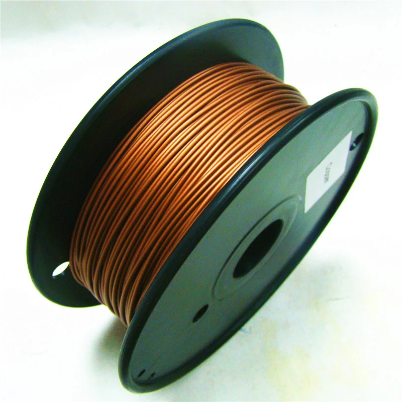
Real filament price
WORK IN PROGRESS! Great tool to compare real price of filament. Only measurement, which accurately tells you how much you can print with your purchased filament, is volume in cm3. Filament vendors should provide price per cm3 which doesn't happen now. So I made this simple tool for you to calculate it.
Example: You are offered 100m of PLA both in 3mm and 1.75mm for $25. With 3mm you will buy 2827cm3 but with 1.75mm just 962cm3 of plastic. That renders 1.75mm deal pretty awful as you will get just one third for the same price.
Filament name
Weight
Length
Diameter
Diameter presets 2.95 mm1.75 mm
Material - presets the density for calculations ABS - 1.08 g/cm3PLA - 1.3 g/cm3
Density
Package price
| Filament name | Price per cm3 | Total volume cm3 | Total wieght kg | Test whistles printed (2.6cm3) |
|---|---|---|---|---|
| Prusa filament | 0.001 $ | 1000 cm3 | 1 kg | ??? |
Stepper Motors
Steps per millimeter - belt driven systems
The result is theoreticaly right, but you might still need to calibrate your machine to get finest detail. This is good start tho.
If you struggle how to use this calculator, try aksing in ℹ steps per mm forum.
Motor step angle 1.8° (200 per revolution)0.9° (400 per revolution)7.5° (48 per revolution)
Driver microstepping 1 - full step1/2 - half step1/4 - quater step1/8 - uStep (mostly Gen6)1/16 - uStep (mostly Pololu)1/16- uStep (Smoothieboard)1/32- uStep (Crazy Smoothieboard)
Belt pitch (in mm)
Belt presets 2mm Pitch (GT2 mainly)MXL belt (2.03mm)T2.5 (2.5mm)3mm Pitch (GT2, HTD)5mm Pitch (T5, GT2, HTD)0.2" XL belt (5.08mm)
Pulley tooth count
| Result | Resolution | Teeth | Step angle | Stepping | Belt |
|---|---|---|---|---|---|
| 0 Click to Share! | micron | 0 | 0° | 1/0th | 0mm |
Example:
M92 g-code can set the steps per mm in real time.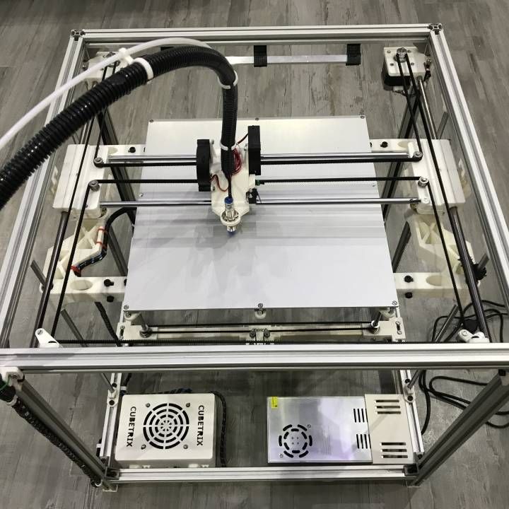 Here is an example with your result for X axis.
M92 X0
Steps per millimeter - leadscrew driven systems
Gives you number of steps electronics need to generate to move the axis by 1mm.
If you struggle how to use this calculator, try aksing in ℹ steps per mm forum.
Motor step angle 1.8° (200 per revolution)0.9° (400 per revolution)7.5° (48 per revolution)
Driver microstepping 1 - full step1/2 - half step1/4 - quater step1/8 - uStep (mostly Gen6)1/16 - uStep (mostly Pololu)1/16- uStep (Smoothieboard)1/32- uStep (Crazy Smoothieboard)
Leadscrew pitch
mm/revolution
Pitch presets M8 - metric (1.25mm per rotation)M6 - metric (1mm per rotation)M5 - metric (0.8mm per rotation)12 (12mm per rotation)16 (16mm per rotation)25 (25mm per rotation)5/16"-18 imperial coarse (1.41111mm per rotation)3/16"-20 imperial (1.270mm per rotation)1/4"-16 Acme (1.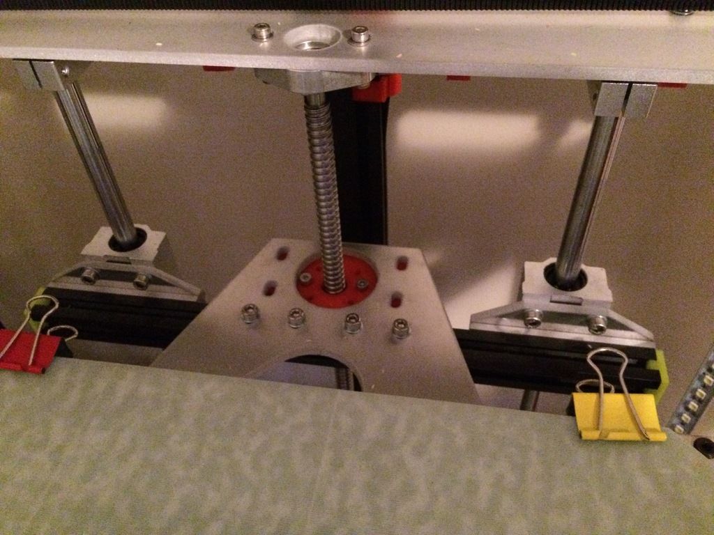 5875mm per rotation)
Gear ratio
| Result | Leadscrew pitch | Step angle | Stepping | Gear ratio |
|---|---|---|---|---|
| 0 Click to Share! | 8 | 1.8° | 1/16th | 2 : 2 |
Example:
M92 g-code can set the steps per mm in real time. Here is an example with your result for X axis.
M92 Z0
Optimal layer height for your Z axis
Helps you to select layer height in a way, that Z axis moves only by full step increments. Z axis isn't usually enabled during inactivity. If the axis is disabled during micro-step, axis jumps to the closest full step and intorduce error. This effect is occuring to some extent even while leaving the Z axis motors enabled. This is most usefull to machines with imperial leadscrews but also for unusual layer heights with metric leadscrews.
Motor step angle 1.8° (200 per revolution)0.9° (400 per revolution)7.5° (48 per revolution)
Desired layer height
Leadscrew pitch
mm/revolution
Pitch presets M8 - metric (1.25mm per rotation)M6 - metric (1mm per rotation)M5 - metric (0.8mm per rotation)12 (12mm per rotation)16 (16mm per rotation)25 (25mm per rotation)5/16"-18 imperial coarse (1.41111mm per rotation)3/16"-20 imperial (1.270mm per rotation)1/4"-16 Acme (1.5875mm per rotation)
Gear ratio
| Layer height | Error over 10cm | Number of steps | Step length |
|---|---|---|---|
| 0 | 8mm | 8 | 1. 8mm 8mm |
| 0 | 8mm | 8 | 1.8mm |
| 0 | 8mm | 8 | 1.8mm |
Acceleration
Max Speed
Input your acceleration settings, distance/length of axis and you can see you your printer will hit your desired speed and for how long.
Acceleration
Distance or axis length
Desired speed
90,000 instructions for setting up all 3D printer mechanics: from belts to speeds ofHome / Useful / Hyde for setting up 3D printer mechanics
04.05.2021
Content
-
- What includes mechanics
- Defects mechanical failure
- How to save settings
- Setup instructions
- Belts
- Motor current
- Motor steps
- Acceleration
- Jerk
- Speed
- Check settings
The quality of the printed models directly depends on the mechanics of the printer, namely on its correct settings.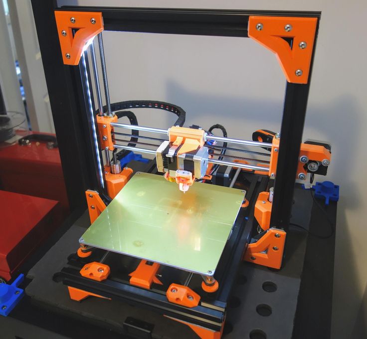 Any elements of the printer wear out over time, so the printer must be set up at least once every 5-6 kg of printed filament. With the help of the short instructions described in this guide, you can quickly and easily set up the mechanics of your printer: belt tension, motor current, motor steps, acceleration, jerk and speed.
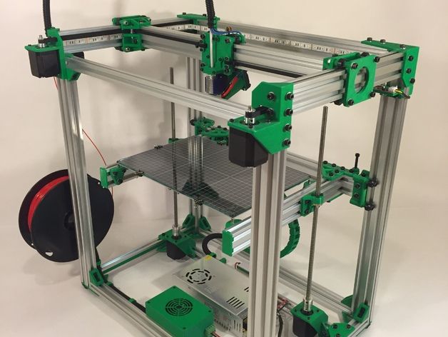
Mechanics includes
3D printers of any design always contain the same things: Axes and rails along which the elements of the printer move and motors with belts that set these elements in motion. In a classic printer design, there are at least 3 motors (one for each axis), 3 rails (one for each axis) and an electronics board that controls the motors. The latter can hardly be called part of the mechanics, but since it controls the engines, it also indirectly affects the quality of the model.
Printing defects due to mechanical problems
Before changing anything in the printer, you need to decide what exactly needs to be configured. Often defects are visible visually. Our blog has an article about most printing defects, which details the reasons for their occurrence. The following is a list of defects and what element of mechanics they are associated with:
-
Layer shifting - Belts, Motor current, Guides
-
Ringing - Guides, Speed
-
Incorrect model geometry - Guides, Motor steps, belts
As you can see, all the above problems do not interfere with the printing process itself, but the result leaves much to be desired. Sometimes mechanical errors can completely stop the printer from working. Therefore, it is better not to take the situation to extremes and, if any problems arise, immediately start checking and configuring the 3D printer.
How to save settings
To fix some defects, you need to change the printer software settings. Therefore, before adjusting the mechanics, it is necessary to understand how to properly store the settings inside the printer.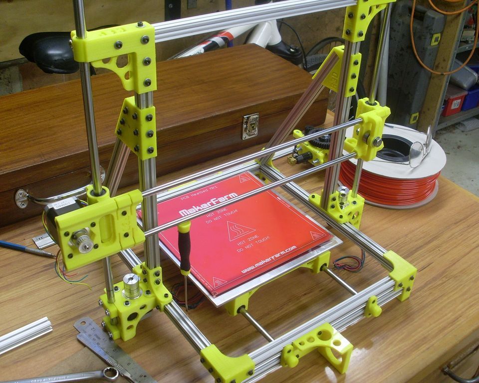 There are 3 ways to do this:
All settings are located in the corresponding menu of the printer
Depending on your firmware, this manual will indicate code sections for MARLIN firmware in the configuration.h file
We first enter the parameters into the printer and then store them in EEPROM - the internal memory of the microcontroller. Or paste all the necessary settings at the beginning of GCODE. To learn how to do this, read our article on working with GCODE and creating macros.
To save to EEPROM, you need to send the printer a command to change some value (which can also be inserted into the initial GCODE), and then send the M500 command (save the current settings to permanent memory). The EEPROM function must be enabled in the firmware, for this you need to remove two slashes in the line:
//#define EEPROM_SETTINGS
Whichever option you choose, you should be careful when using any commands. You will not be able to harm the printer in any way when changing the settings, but if you make a mistake, you will have to look for the cause of possible further problems for a long time.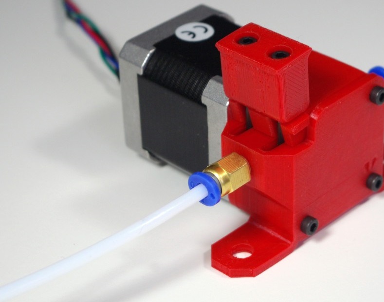
Setting Instructions
Now you can start setting up the printer itself. If you decide to set several parameters at once, then it is better to use the order of adjustments as in the article, since some of the settings are related to each other and if you use the wrong order, adjusting one element of the mechanics will override the settings of another element. For example, you should not adjust the motor steps before tightening the belts, as changing the length of the belts will change the "true" steps per millimeter of the motors. Also, before setting up, you must make sure that there are no backlashes in the printer frame, tighten all belts.
Belts
The first thing to start setting up the printer is the belts. They directly affect the geometry of the model and, when pulled too much, they cause a lot of problems: displacement of layers, changes in geometry, ripples. First you need to make sure the belt is intact. To do this, look at the entire belt, especially the areas where the belts bend. If the belt has outlived its usefulness, then you can see a section of the belt where the distance between the teeth has greatly increased and a metal wire (cord) is visible between them. This means that it's time to completely change the belt.
Broken belt with broken cords
If the belt is intact or you have already replaced it, then you can proceed to the next step. Depending on the design of your printer, you need to move the roller through which the belt passes. The tension should be such that the carriage or table moves effortlessly, but at the same time, when moving quickly, the belt should not slip the teeth on the motor gear. Adjust the tension of the belts on each axis of the printer using this method.
Tip: if your printer came with a belt tensioner in the form of a spring attached to the belt itself, remove it. Due to the flexibility of this tensioner, printing defects will occur, such as protruding corners on the model.
It is better to adjust the belt without using this tensioner.
Belt tensioner
Current motors
As we know from the school physics course, the power of the engine depends on the voltage and current strength. Since the voltage on all printer electronics is the same everywhere, the only thing that can be changed is the current on the motor. More precisely, it should be said the maximum current that the driver will supply to the motors. To change this limit, you need to climb inside the case and find the printer board. On it you will see the printer driver. We are interested in a small potentiometer on the driver itself (in the picture below it is indicated as a tuning resistor).
Example of potentiometer location on driver
For adjustment, you will need a voltmeter and a small Phillips or flathead screwdriver. Before proceeding further, it is necessary to calculate the maximum current supplied to the motors. Different formulas are used for different drivers, the most popular ones will be listed in the table below:
| Driver name | Formula | Explanations |
| A4988 | Vref = Imax * 1.25 for R100 | To understand which formula to use, you need to find a resistor with the signature R100 or R050 on the driver. They are located next to the driver chip. |
| DRV8825 | Vref = Imax / 2 | |
| LV8729 | Vref = Imax / 2 | |
| TMC2208 TMC2100 TMC2130 | Vref = Imax * 1.41 | One formula for all drivers |
The value of the maximum current (Imax) depends on the motor controlled by the driver. This can be found in the engine specification or on the sticker on it. The following are the currents for the most popular motor models:
17HS4401 - current 1.7 A
17HS8401 - current 1.8 A
17HS4402 - current 1.3 A
Substituting the value into the formula, we get the Vref value for the maximum current supplied to the motor. But at this value, the engine will get very hot, so the resulting Vref value must be multiplied by 0.7. For example, for a motor with a maximum current of 1.5 A and a TMC 2208 driver:
Vref=1.5*1.41*0.7=1.48V
Now the resulting value can be used when configuring on the printer itself. To do this, disconnect the wires going to the motors, turn on the printer and place one voltmeter probe in the center of the trimmer, and the second probe to the negative terminal on the power supply (you can also use the negative terminal on the printer board and the contact on the driver, labeled as GND). You will see some value on the voltmeter screen. Turn the trimmer clockwise to decrease the Vref value and counterclockwise to increase it.
Attention: you should not specify a Vref value higher than the maximum calculated for your engine! Otherwise, the engine will soon break down!
Once you have adjusted the value on the drivers, you can turn off the power to the printer, connect the motor wires, and put the case back together. This completes the driver setup.
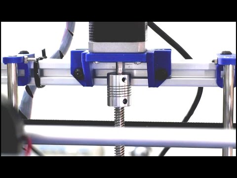
Motor steps
When setting up motor steps, you will need a ruler. For convenience, you can use the program Repetier-Host. The adjustment for each of the three axes occurs according to the same algorithm:
-
Set the caret to zero coordinates (Autohome or G28)
-
Move the carriage some distance
-
We measure how far the carriage has traveled
-
We calculate the correct number of steps per millimeter using the formula:
True steps per millimeter = current steps per millimeter * reported distance / distance traveled
For example, if the printer was set to 100 steps/mm, we tell the printer to move 80mm and the printer travels 87. 5mm. Then the correct steps per millimeter would be 100 * 80 / 87.5 = 91.42 steps/mm. For the convenience of measurements, you can fix a ruler on the table, and a thin object, such as a needle or pin, on the carriage. Then it will be possible to accurately measure the distance traveled. The extruder uses a partially different algorithm to measure distance:
-
Inserting plastic into the extruder
-
Cut it right at the outlet
-
We give the printer a command to stretch the plastic a certain distance (at least 100 millimeters)
-
Cutting plastic again
-
We measure the length of the resulting piece of plastic
-
We use the formula from the previous algorithm
Next, the settings data must be inserted into the firmware in the line:
#define DEFAULT_AXIS_STEPS_PER_UNIT {X,Y,Z,E0}
X,Y,Z and E0 should be replaced by the steps per millimeter for each of the axes, respectively. Otherwise, you need to insert this line into the initial GCODE:
M92 Ennn Xnnn Ynnn Znnn
Instead of nnn in each of the parameters, you must substitute the steps per millimeter for each axis. If you want to adjust the steps only for not all axes, then you can remove unnecessary parameters.
Acceleration
This parameter is responsible for the rate of change of speed. That is, how fast the printer will change its speed. This affects the nature of the movement of the hot end relative to the table. If the acceleration is too small, then the printer will print slowly, if it is too large, then the outer surface of the model will have visual defects: fading waves will be visible near each of the corners, as in the picture below.
To set up acceleration, you need to follow simple steps:
-
Cut a model of a standard test cube with a wall thickness equal to one nozzle diameter, without filling and top layers, bottom 2-3 layers;
-
Open GCODE file in notepad;
-
Find the G28 command at the very beginning and insert the line data after it:
M201 X5000 Y5000
M204 P500 T500
-
Save the changes, print the model according to the received GCODE and note at what parameters P and T it was printed;
-
Open the same GCODE file and change the P and T values on the second line, adding 500 to each;
-
Repeat steps 4-5 at least 3 times;
As a result, you will get several test cubes, some of which will show waves at the corners. Choose the cube that is printed with the highest P and T parameters, but that no waves can be seen on it. The number in parameter P will be the desired acceleration value. To save this value, you need to find 2 lines in the firmware:
#define DEFAULT_MAX_ACCELERATION {X,Y,Z,E0}
#define DEFAULT_ACCELERATION {nnn}
Instead of X and Y, you should put an acceleration twice as high as found earlier. And instead of nnn, you need to put the acceleration value found earlier. Otherwise, you need to insert a line in the initial GCODE:
M204 Pnnn Tnnn
In the parameters P and T, you need to put the value of the found acceleration. After that, the acceleration setting can be considered complete.
Jerk
A jerk indicates the speed with which to start accelerating. It affects the model in a similar way as acceleration: it creates ripples around the corners of the model. But it also increases the protrusion of the corners if the jerk is too small.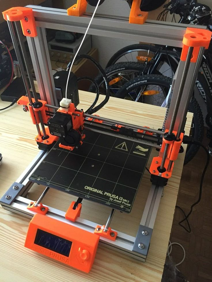 The jerk setting is also similar to the acceleration setting:
-
Cut a model of a standard test cube with a wall thickness equal to one nozzle diameter, without filling and top layers, bottom 2-3 layers.
-
Open GCODE file in notepad
-
Find the G28 command at the very beginning and insert the line data after it:
M205 X5 Y5
-
Save the changes, print the model according to the received GCODE and note at what X and Y parameters it was printed
-
Open the same GCODE file and change the X and Y values on the second line, adding 2 to each
-
Repeat steps 4-5 at least 3 times
As a result, you will get several cubes. Find a non-rippled cube printed at the highest X and Y settings. This will be the jerk value for your printer. To save them, you need to find the line in the firmware:
#define DEFAULT_XJERKnnn
#define DEFAULT_YJERKnnn
It is necessary to substitute the jerk values for the X and Y axes, respectively.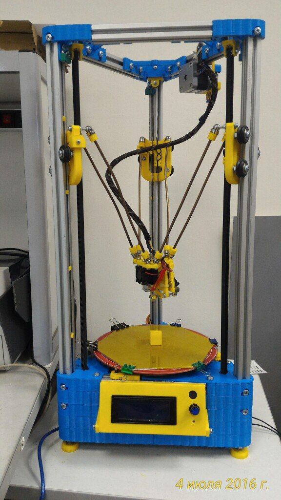 Otherwise, you need to substitute the command in the starting GCODE:
M205
Instead of nnn, you need to substitute the jerk value found earlier. This completes the jerk setting.
Speed
In fact, there are many different speed parameters, the values \u200b\u200bof which vary greatly. Let's take a look at the main ones:
This parameter is responsible for moving the nozzle without extruding plastic. The value is in the range from 80 to 120 mm/s. Limited only by the maximum speed at which the motors can rotate. Does not affect the model
This speed is important because it indirectly affects the adhesion of the model to the table. Usually lies between 15 and 30 mm/s
-Print speed of inner walls
Usually set to about 60 mm/s, it only affects the strength of the model. Depends on the maximum amount of plastic that the extruder can push through the nozzle
-Speed of printing outer walls
Usually about half the printing speed of the inner walls (30 mm / s). It affects not only the strength of the model, but also the appearance: the lower this speed, the smoother the walls will be.
The standard value is 80 mm/s, it only affects the strength of the model
Usually set from 20 to 40 mm/s, the quality of the upper layer of the model depends on it: the lower the value, the smoother the cover.
All of the above parameters are selected experimentally. Usually there is a simple rule: higher speed - lower quality. Therefore, do not try to find the ideal value for all situations. It is better to find values for fast printing, quality printing, and an average that will be used for most models.
Check settings
The last step in setting any of the above parameters will be to check the result. If you have written parameters in firmware or saved them in EEPROM, you can use the M503 command. It will display all printer settings on the computer. To test the settings in practice, you can print several test models:
Classic Benchy
Simple calibration cube
Calibration cat
On each of the above models, defects will be clearly visible, if they still remain after the mechanics are adjusted.
#Useful
Expert in the field of additive and subtractive technologies, 3D equipment and CNC machines with over 10 years of experience.
Share
all materials
Do you have any questions?
Our experts will help you with the choice of 3D equipment or accessories, consult on any questions.
How to calibrate a 3D printer in 5 steps・Cults
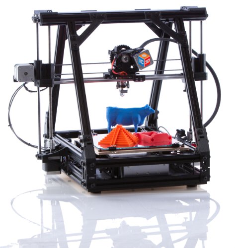
The first 3D printer was developed in the 1980s by Charles W. Hull, but the technology only became popular in the early 2000s. Since then, 3D printing has come a long way and is used all over the world for personal and industrial applications.
3D printing enthusiasts will attest that it takes a long learning curve to make good use of this technology and related software. One of the hardest parts of this learning curve is machine calibration. Here we will cover the basic calibration procedure required for 3D printers. This article is written from the point of view of simple and reusable Printrbot and assumes that the user has a digital caliper, ruler, ribbon, and thread. If the reader does not use Printrbot simple and Repetier, then there is no problem, any combination of printer and software will do.
Open Repetier, connect the printer and select the manual tab. Select the toggle button with simple mode disabled and enter "M501" in GCode. Press the Enter key and scroll until you find a code that looks like "echo": M92 X__ Y__ Z___ E__.".
Pay special attention to this line of code, as it will be important in the future. to the side and place a piece of tape on the printer bed, parallel to where it will not move when you move the X axis. Mark the tape where the X axis currently points.
Using Repetier, instruct the printer to move the X axis starting at 70mm and make another mark at the end of the X axis. The printer just moved to where it thinks 70mm is. Now, using a caliper, measure the distance between the two marks to determine the actual travel distance.
A new M92 value needs to be found, using the current M92 value recorded in step 1.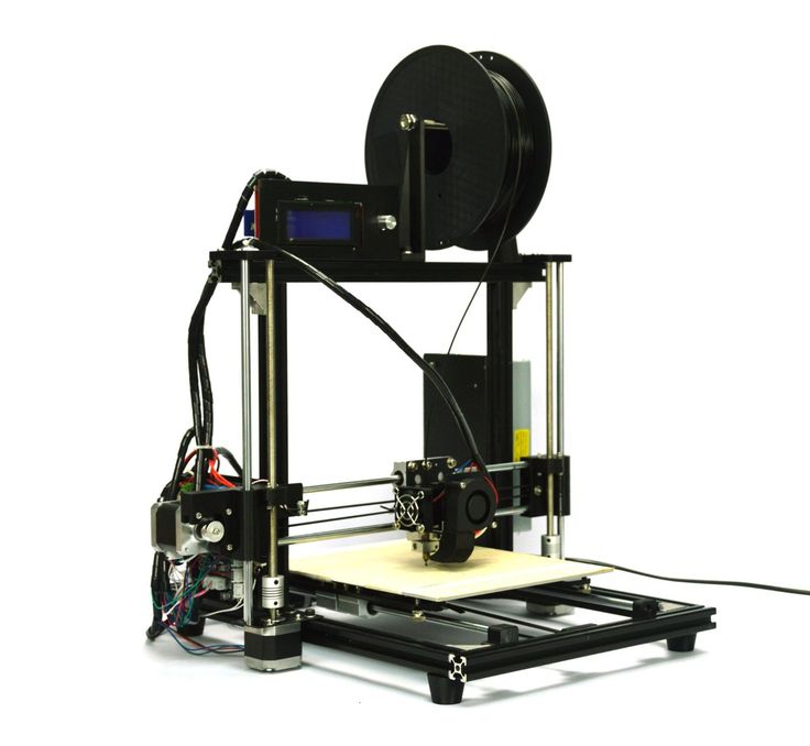 This can be achieved using the following equation. After calculating the new value M92 for the x-axis, it must be entered in the G-code.
New M92 value = desired travel/actual travel * actual M92 value.
The process of calculating the Y-axis is the same as calculating the M92 actual value for the Y-axis. Note where the Y-axis starts, enter a value for its offset, and note where the Y-axis ends. With a caliper, you can determine the actual distance travelled. Using the same equation, a new M92 value can be calculated and entered into GCode.
New M92 value = desired travel/actual travel * actual M92 value.
The Z axis is much easier to calculate with a ruler than with a caliper. To get started, simply specify the x, y, and z axes and position the ruler parallel to the plate. Select a point on the print shoulder along the Z axis and measure the distance from the printing plate to that point. Now, as before, enter a value for the x-axis offset and measure how much it has moved.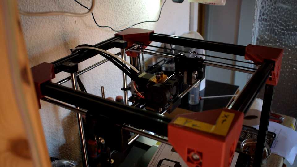 Formula for determining the new value of M92 for the Z axis is slightly different from the other two.
Input measurement/actual measurement * Old M92 value = New M92 value.
Enter this value in the GCode for the Z axis.
This is the last item to check in the calibration process. To calibrate an extruder, determine how much filament comes out of the extruder. To begin, heat the hot end to the suggested temperature and make a mark on the thread about 3 cm from the entry point. Command the printer to extrude 10mm of filament and take a measurement to determine the distance between the two points. If the distance is 10 mm or any other value is entered, then the extruder is calibrated. Otherwise, a new value of E M9 must be calculated2 and enter it into GCode. This value can be found using the formula below.
Desired measurement/actual measurement * current M92 value = new M92 value.
Calibrating a 3D printer might seem like a daunting task at first, but it's not, all you're doing is figuring out if the motion you enter matches the actual motion.