3D printer smooth rods
Smooth Rod | Hackaday
September 25, 2022 by Kristina Panos
What’s the deal with getting things done? There’s a Seinfeld anecdote that boils down to this: get a calendar, do a thing, and make a big X on each day that you do the thing. Pretty soon, you’ll thirst for chains of Xs, then you’ll want to black out the month. It’s solid advice.
[3D Printy] likes streaks as well, and made several resolutions at the beginning of 2022. As the first of 30 videos to be made throughout the year, they featured this giant 3D printed counting mechanism (video, embedded below) that uses empty filament spools, some 3D prints, and not much else. These are all Hatchbox spools, and it won’t work for every type, but the design should scale up and down to fit other flavors.
This isn’t [3D Printy]’s first counter rodeo — he’s made several more normal-sized ones and perfected a clever carryover mechanism in the process, which is of course open-source. So each spool represents a single digit, and there are printed parts in the core that make the count carry over to the next spool. Whereas the early counters used threaded rod, this giant version rides on 2.5 mm smooth rod, so the spools can slide apart easily. But how does everything stay together? A giant elastic band made of TPU filament, of course — because the answer is always in the room.
Check out the video after the break, and stay for the 900%-sped-up assembly at the end.
Continue reading “Empty Spools Make Useful Tools, Like Counters” →
Posted in green hacks, Misc HacksTagged 3D printer filament spool, counter, smooth rod, TPUMarch 16, 2019 by Tom Nardi
When you really start fine-tuning your 3D printer, you might start to notice that even the smallest things can have a noticeable impact on your prints. An open window can cause enough of a draft to make your print peel up from the bed, and the slightly askew diameter of that bargain basement filament can mess up your extrusion rate.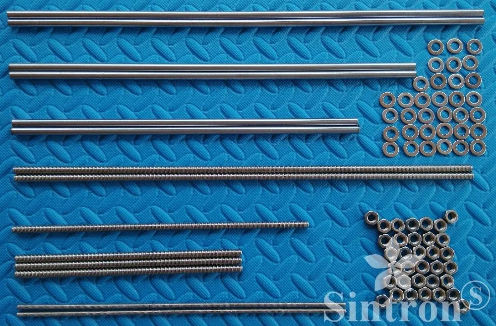 It can be a deep rabbit hole to fall down if you’re not careful.
One element that’s often overlooked is the filament spool; if it’s not rotating smoothly, the drag it puts on both the extruder and movement of the print head can cause difficult to diagnose issues. For his custom built printer, [Marius Taciuc] developed a very clever printable gadget that helps the filament roll spin using nothing but the properties of the PLA itself. While the design might need a bit of tweaking to work on your own printer, the files he’s shared should get you most of the way there.
All you need to do is print out the hubs which fit your particular filament spools (naturally, they aren’t all a standard size), and snap them on. The four “claws” of the hub lightly contact a piece of 8 mm rod enough to support the spool while limiting the surface area as much as possible. The natural elasticity of PLA helps dampen the moment that would result if you just hung the hub-less spool on the rod.
The STL files [Marius] has provided for his low-friction hubs should work fine for anyone who’s interested in trying out his design, but you’ll need to come up with your own method of mounting the 8 mm rod in a convenient place.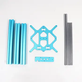 The arms he’s included are specifically designed for his customized Prusa Mendel, which is pretty far removed from contemporary desktop 3D printer design. Something to consider might be a piece of 8 mm rod suspended over the printer, with enough space that you could put a couple spools on for quick access to different colors or materials.
Hackers have been trying to solve the spool friction issue for years, and as you might expect we’ve seen some very clever designs in the past. But we especially like how simple [Marius] has made this design, and the fact that you don’t need to source bearings to build it. If you’re thinking of giving this new design a shot, be sure to leave a comment so we know how it worked out for you.
Continue reading “Printable Filament Spool Hub Skips The Bearings” →
Posted in 3d Printer hacksTagged bearing, filament spool, hub, PLA, smooth rodOctober 15, 2018 by Tom Nardi
We’ve been seeing an influx of repurposed 3D printers recently.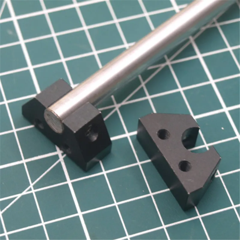 Thrifty hackers have been leveraging cheap 3D printers as a way to bootstrap their builds, on everything from laser engravers to pick and place machines. There’s nothing wrong with that, and honestly when you can get a cheap 3D printer for less than the cost of the components separately thanks to the economies of scale, you’d be foolish not to.
But there’s still something to be said for the classic RepRap mentality of building things using printed parts and smooth rods. Case in point, the largely 3D printed plotter that [darth vader] sent in for our viewing pleasure. This isn’t somebody sicking a pen on the extruder of their open box Monoprice special, this is a purpose built plotter and it shows. In the video after the break you can see not only how well it draws, but also how large of a work area it has compared to a modified 3D printer.
If you know your way around a 3D printer, most of it should look pretty familiar to you. Using the same GT2 belts, steppers, end stop switches, and linear bearings which are ubiquitous in 3D printers, it shouldn’t be difficult to source the parts to build your own.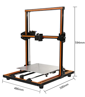 It even uses a Mega 2560 with RAMPS 1.4 running Marlin 1.1.9 for control.
The biggest difference is the physical layout. Since there’s no heavy hotend or extruder assembly to move around, the plotter has a cantilever design which gives it far greater reach. As it only needs to sightly lift the pen off the paper, there’s no need for a complex Z axis with leadscrews either; a simple servo mounted to the end of the arm is used to raise and lift the pen. We especially like the use of a tape measure as strain relief for his wiring, a fantastic tip that we (and many of you) fell in love with last year.
While it’s hard to beat just tossing a pen onto the business end of your desktop 3D printer in terms of convenience, we think it’s pretty clear from this build that the results don’t quite compare. If you want a real plotter, build a real plotter.
Continue reading “The 3D Printed Plotter You Didn’t Know You Needed” →
Posted in 3d Printer hacks, Arduino HacksTagged linear bearing, plotter, RAMPS, reprap, smooth rod3D Printer 8mm Chrome Plated Smooth Rod hobbyking
JavaScript seems to be disabled in your browser.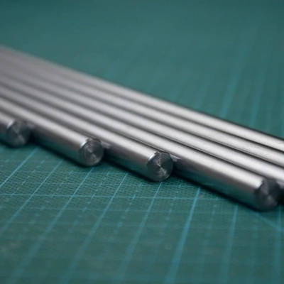
You must have JavaScript enabled in your browser to utilize the functionality of this website.
Proceed to Checkout
Total Price
$0.00
Cart 0
want FREE shipping? Click here to find out more!
{{/findAutocomplete}}
SKU: {{sku}} {{#isFreeshipppingEnabled}} Free Shipping on Eligible Orders {{/isFreeshipppingEnabled}}
{{#isDiscountFlag1Enabled}}
{{/isDiscountFlag1Enabled}} {{#isDiscountFlag2Enabled}}
{{/isDiscountFlag2Enabled}} {{#isDiscountFlag3Enabled}}
{{/isDiscountFlag3Enabled}} {{#isDiscountFlag4Enabled}}
{{/isDiscountFlag4Enabled}} {{#isDiscountFlag5Enabled}}
{{/isDiscountFlag5Enabled}} {{#isDiscountFlag6Enabled}}
{{/isDiscountFlag6Enabled}} {{#isDiscountFlag7Enabled}}
{{/isDiscountFlag7Enabled}} {{#isDiscountFlag8Enabled}}
{{/isDiscountFlag8Enabled}} {{#isDiscountFlag9Enabled}}
{{/isDiscountFlag9Enabled}} {{#list_image_url}}{{/list_image_url}} {{^list_image_url}}{{/list_image_url}}
{{#isFreeshipppingEnabled}}
Free Shipping on Eligible Orders
{{/isFreeshipppingEnabled}} {{#isAddToCartEnabled}} {{#isWarehouseAddToCartEnabled}} {{^is_combo_product}}
QTY: {{#isAgerestrictionEnabled}} {{/isAgerestrictionEnabled}} {{^isAgerestrictionEnabled}} {{/isAgerestrictionEnabled}}{{/is_combo_product}} {{/isWarehouseAddToCartEnabled}} {{/isAddToCartEnabled}} {{#availableInOtherWarehouses}} {{{availableInOtherWarehouses}}} {{/availableInOtherWarehouses}} {{#is_combo_product}} {{^isProhibited}} View Details {{/isProhibited}} {{/is_combo_product}} {{#isProhibited}}
We are sorry, this product is not available in your country
{{/isProhibited}}
{{#hbk_price.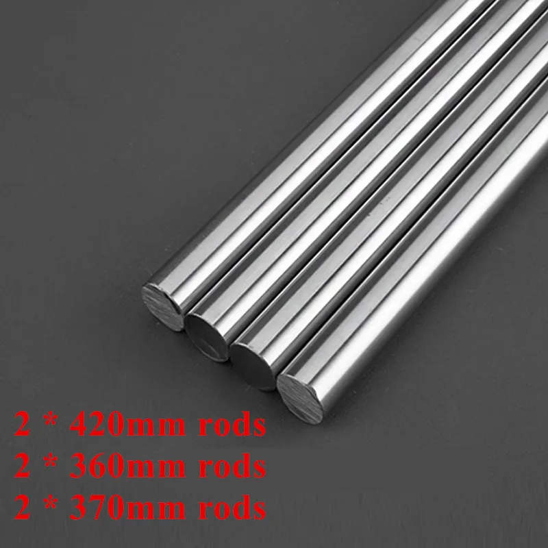 stock_2_group_0_original_formated}} {{hbk_price.stock_2_group_0_original_formated_label}} {{hbk_price.stock_2_group_0_original_formated}} {{/hbk_price.stock_2_group_0_original_formated}} {{#is_combo_product}} {{hbk_price.stock_2_group_0_combo_price_label}} {{/is_combo_product}} {{hbk_price.stock_2_group_0_formated}} {{#hbk_price.stock_2_group_0_original_formated}} {{hbk_price.stock_2_group_0_you_save_formated_label}} {{hbk_price.stock_2_group_0_you_save_formated}} {{/hbk_price.stock_2_group_0_original_formated}}
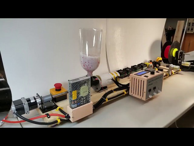
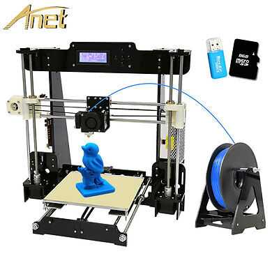
What a 3D printer for personal use consists of and how it works
Do you want to assemble a 3D printer with your own hands from separate components? It is not as difficult as it seems at first glance.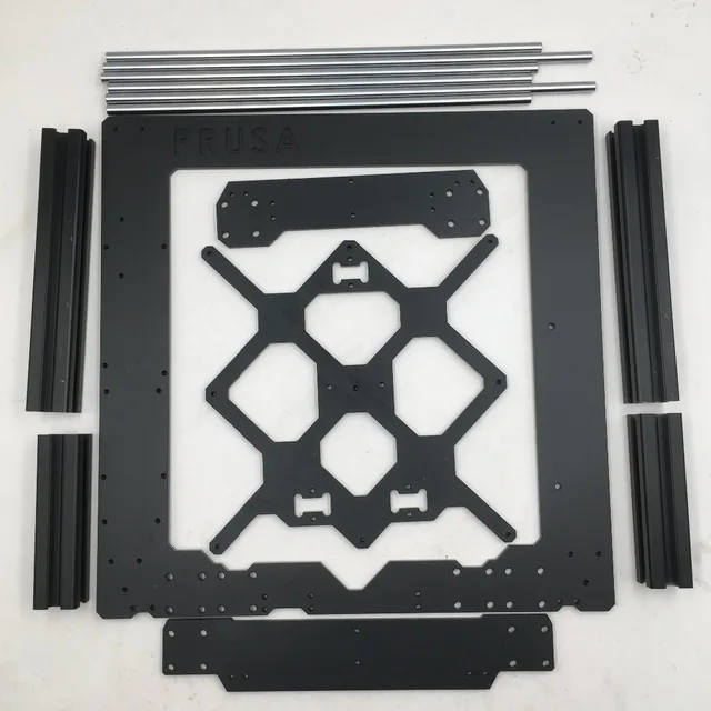 Almost all personal 3D printers use the same approach to 3D printing, differing in detail. Their design looks extremely simple: 4 or 5 stepper motors, an extruder with a heater and a temperature sensor, a heated platform, three end sensors at the zero mark of the axes. More sophisticated printers may have a second extruder with a heater and a temperature sensor, a fan to cool the head, and end sensors at the maximum axis marks.
It is impossible to connect actuators and sensors directly to a computer, so an intermediate link is used - a control controller, for which it is necessary to prepare a special G-code from a mathematical 3D model - a simple set of commands that determine the sequence of printer actions. Certain types of controllers have their own card reader with a slot for an SD memory card, from which G-codes can be read directly. In this case, a computer is not required, and a few buttons and an LCD display are enough to control the 3D printer.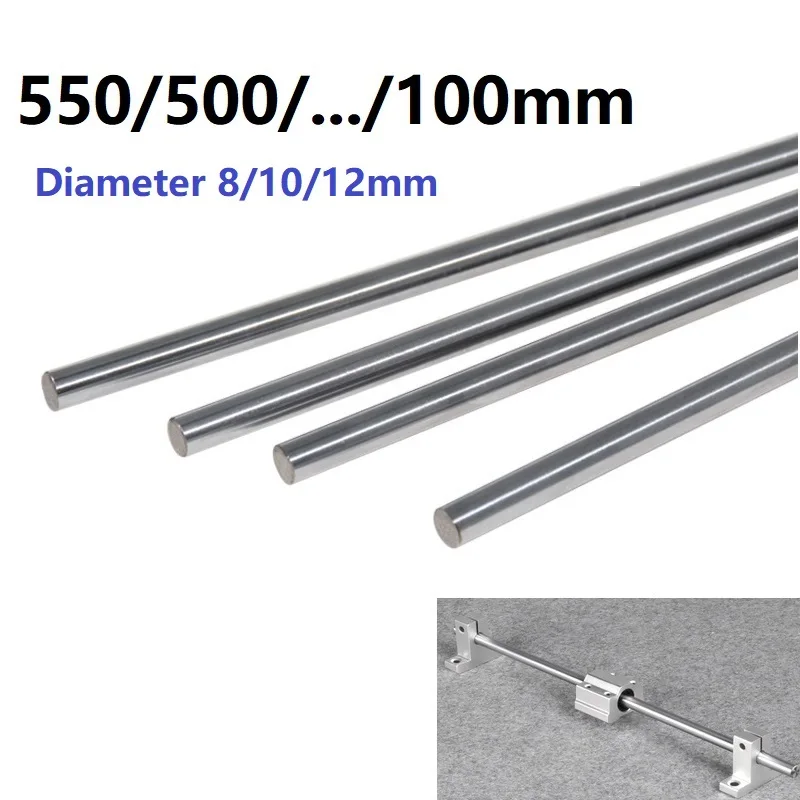 Control controllers are most often created under the Arduino IDE development environment.
The movement of the print head (extruder) occurs in three planes - along the axes X, Y and Z, for which stepper motors are used with a typical accuracy of 1.8 ° per step. Auxiliary elements are timing belts and rollers along the X and Y axes. Often, threaded metal rods or special screws are used for precise positioning along the Z axis. A controller-controlled 3D printer moves the print head, extruding molten plastic, thereby fusing the model layer by layer.
NEMA 17 Stepper Motors
NEMA 17 is the size reference for a standard footprint for various stepper motors, which measures 1.7x1.7 inches (43.2x43.2 mm). The smaller size is referred to as NEMA 14 (1.4x1.4 in. or 35.6x35.6 mm).
Stepper motors can have three modes of operation: full step, half step and micro stepping. During the full step mode, the stepper motor rotates its axis 360 degrees, making 200 steps, during the half step mode - 400, and in the microstep mode, each step is divided into 4, 8 or 16 parts.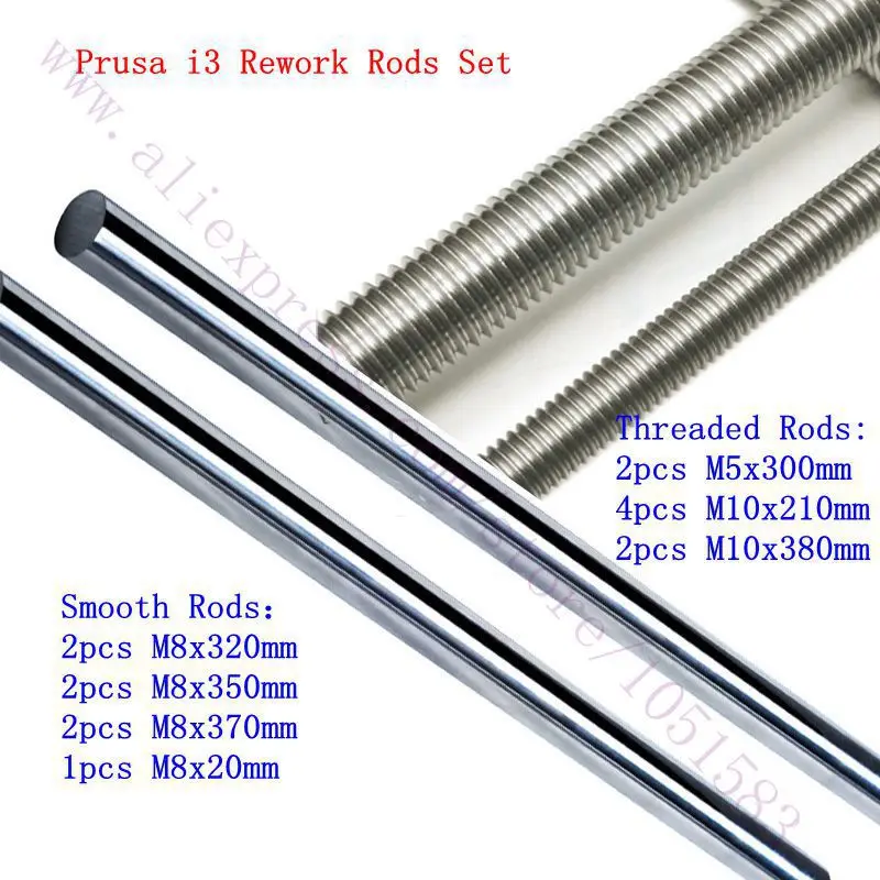 Motor control in microstepping is so complex that special stepper motor controllers are used for it. Stepper motors are available in 4V, 8V and 12V.
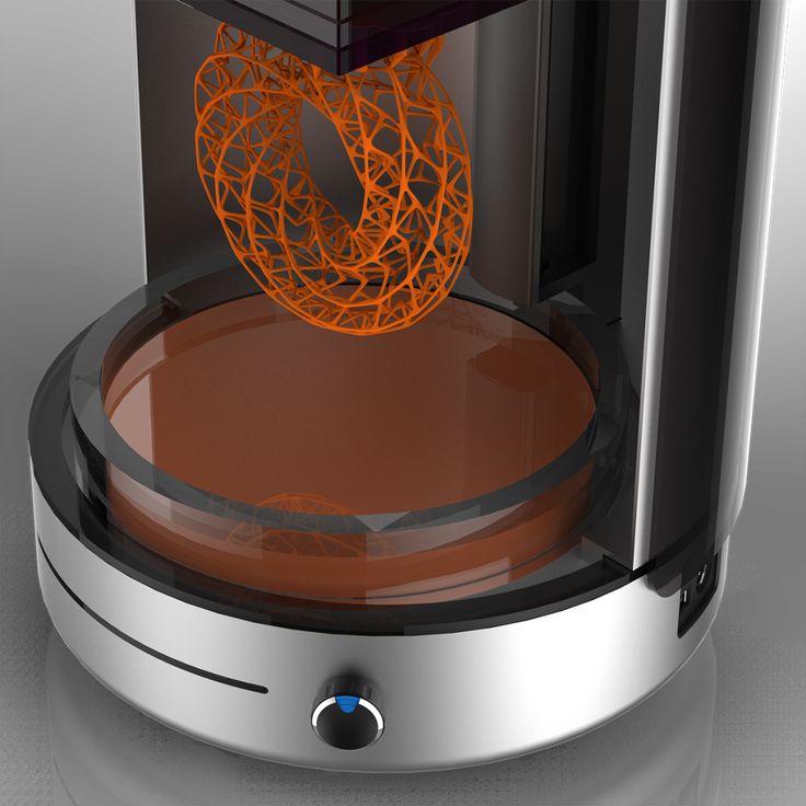
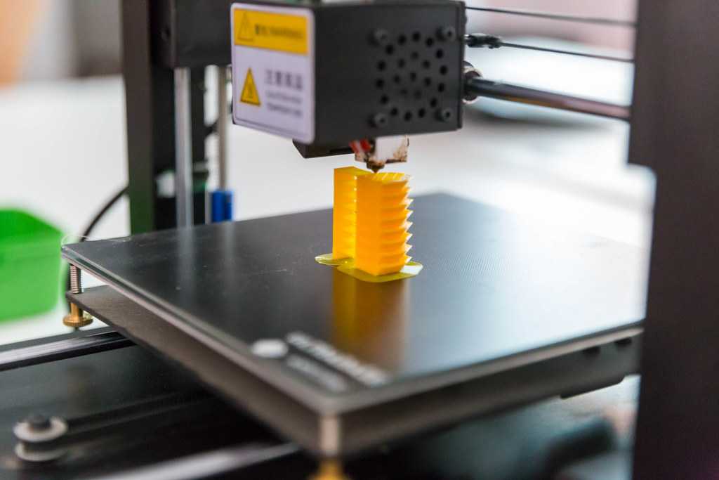
Extruder
The function of uniform distribution of plastic and other materials over the working surface is performed by the extruder, which melts and feeds thermoplastic (ABS or PLA) through the nozzle onto the surface of the table. Being the most complex part of a 3D printer, the extruder consists of a plastic feed drive and a thermal head.
The extruder drive, using a gear mechanism, pushes out a plastic thread with a diameter of 1.75 or 3 mm. Most modern drives use a stepper motor to better control the filament feed to the thermal head. The filament is fed into an aluminum thermal head with a built-in heater, where it is heated to a temperature of 170-260 ° C, depending on the type of plastic, and turning into a semi-liquid state, it is squeezed out of the print head, the hole diameter of which is usually in the range from 0.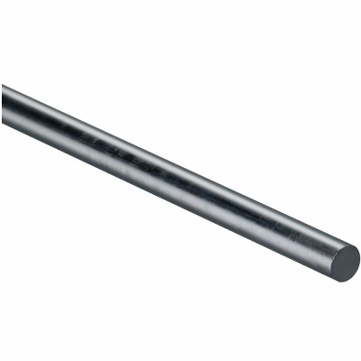 35 to 0, 5 mm.
Printable surface
The work surface on which 3D parts are formed is called a table or platform. Its dimensions vary depending on the printer model and are usually in the range from 150 to 200 mm 2 . Most manufacturers of 3D printers offer a heated platform already in the kit, or as an additional option. There is always the opportunity to make a heated platform yourself from improvised material. The task of the platform is to prevent breaks or cracks in the model, as well as to ensure reliable adhesion between the first layers of the printed part and the work surface.
The top of the platform is made of glass or aluminum for better heat distribution over the entire area and a smooth and even surface. Glass gives a more even surface, while aluminum distributes heat better in case of heating. To prevent the model from tearing off during printing, the surface of the platform is often covered with some kind of sticky mass or film.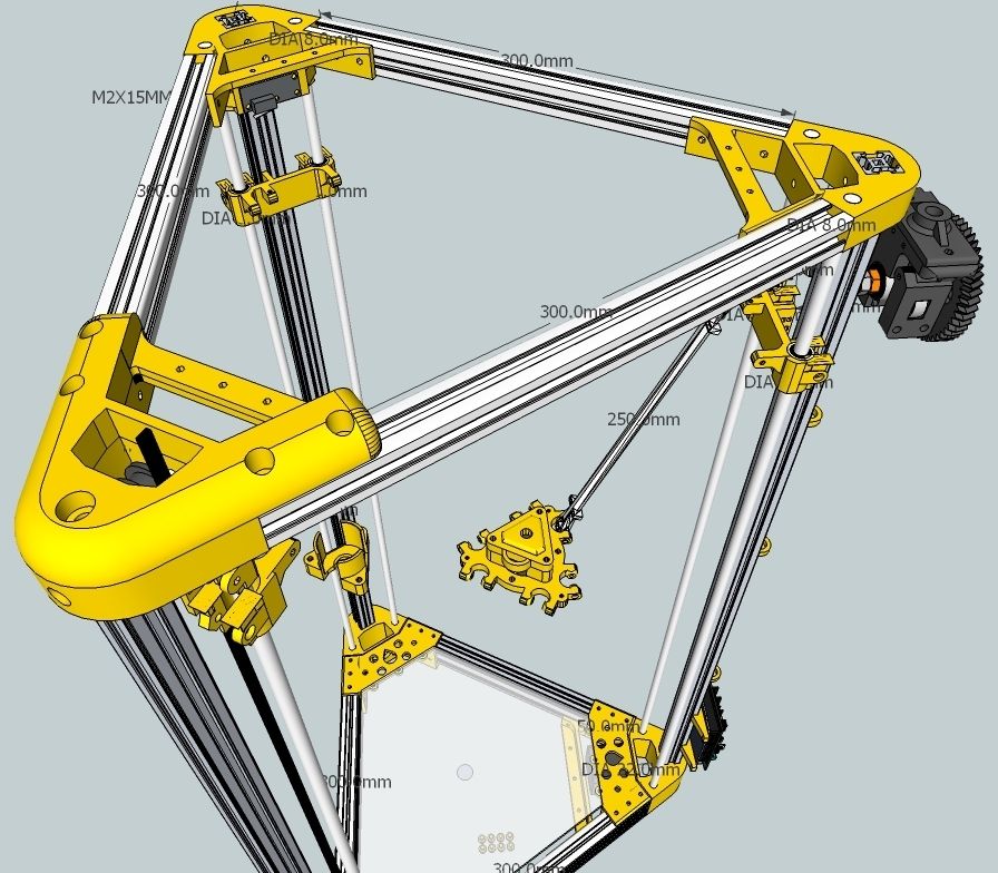 Such materials often consist of Kapton or polyamide tape, depending on the type of plastic.
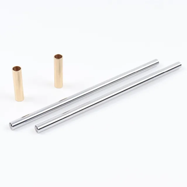
Linear motor
The drive used (linear motor) largely determines the accuracy and speed of printing, as well as the frequency of maintenance of the 3D printer. Typically, smooth, high-precision metal rods are used for each axis, and plastic or bronze ball bearings are used to move over each rod. Linear ball bearings provide longer life and better performance, but they are noisier than bronze bearings, which in turn are more difficult to calibrate at the time of assembly.
End sensors
The range of motion of linear actuators is usually limited by mechanical or optical detents - the simplest end sensors (EndStop), which signal the approach of the printer head to the edge of the working surface in order to prevent it from going beyond the platform. Fixtures are also used to define the origin (0,0,0) in all three axes.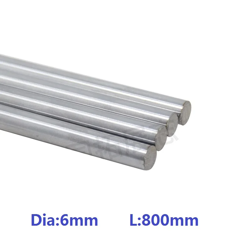
Strictly speaking, the presence of clamps is not mandatory in the operation of 3D printers, but their presence allows you to calibrate the printer before printing, which makes printing more accurate and accurate. End sensors are of two types: pressure and optical. Optical ones are more accurate, but to simplify (for example, along the X-Y axes), you can also use pressure ones.
Printer frame
What connects all the elements described above into a single whole is called the frame. The shape of the frame, and especially the material from which it is made, quite strongly affect the accuracy and quality of the print. The frame design based on the slot principle, when plastic or even plywood sheets cut by a laser, are connected by combs into grooves and then twisted with bolts and nuts, greatly simplifies the assembly of a 3D printer and is more accurate for calibration, but does not contribute to noise suppression, and fasteners have to be tightened over time. If the frame contains threaded metal rods, then the device turns out to be quieter, but the assembly and calibration process becomes more complicated.
If you still prefer to purchase a ready-made 3D printer, then pay attention to the models that are currently popular on the market:
In addition, visiting our stores in Moscow and St. Petersburg, you can even touch some of them with your own hands.
Manufacturers: Mbot 3d
Published: 06/07/2014
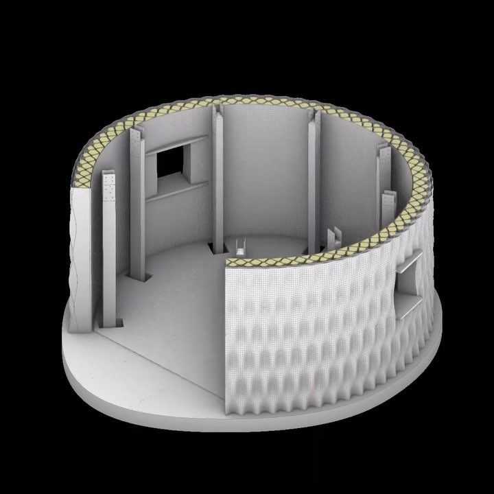
Binder Jetting - 3D Printing of Resin Sand Molds and Cores
Binder Jetting 3D Printing Basic Operations|Flow Flow Diagram|Example of Binder Jetting Equipment Layout Main Benefits|Materials|3D Printers
The principle of operation of additive 3D printing machines with sand is to selectively apply binder microdroplets to the surface of a specially prepared sand mixture in accordance with the layer configuration. Sequential layering allows molds and cores to be produced directly from CAD data. The sand control system provides the possibility of partial recovery of free sand and its reuse. Learn more about Binder Jetting technology.
Basic 3D Printing Binder Jetting
| Application of the first thin layer of the specially prepared oven on the surface of the elevator plate of the sand bin | Selective application of binder to particles sand mixture using horizontal movement print head | Completion of the formation of |
| Reapplying sand over the formed layer | Repeat steps 2,3,4 until complete process build sand mold | Removing the printed |
Brief diagram of the additive manufacturing process
| Analysis of the drawing of a cast part for manufacturability, selection of a casting method, assignment of standards casting accuracy, production conditions, etc. | Design of sand-resin mold and cores. Development of gates and feeders. Creation of a CAD model of the form in stl format | Mathematical modeling of casting processes , making adjustments to the CAD model of a foundry mold |
| Loading stl file to printer and 3D printing with additive machines by Binder Jetting technology | ||
| S-Max Pro | ||
| S-Print | ||
| S-Max | ||
| | | |
| Extraction of sand molds from printing hopper, cleaning, collection of free sand in separator | Sand mold assembly and installation of rods, heat treatment if necessary | Metal casting |
| | | |
| Extraction of castings, removal of gating and feeding structures | Finishing machining castings | Part Quality Control |
Composition of equipment for printing sand-polymer forms and | |
| Binder Jetting |
Based on the specific conditions of the customer, the composition of the kit can change, providing
the needs of both research institutions and large industrial enterprises. Some pieces of equipment can be replaced with similar ones according to
at the request of the customer, including domestic production.
| one. | S-Max installation | eight. | Sandbag unloading station |
| 2. | Double chamber mixer | 9.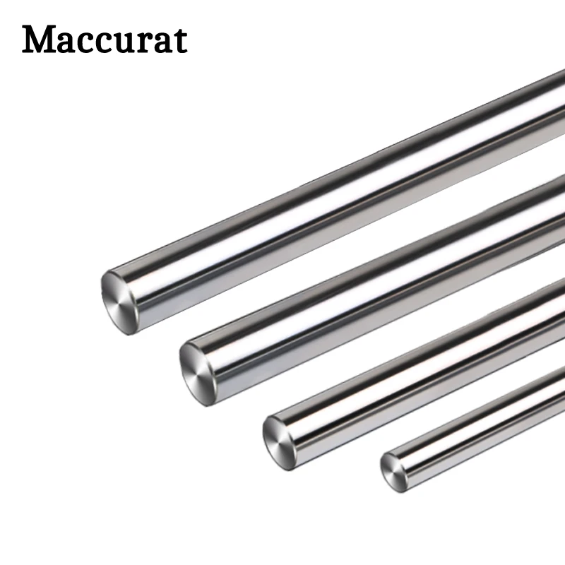 | industrial vacuum cleaner |
| 3. | Roller conveyor | ten. | Separator |
| four. | Working hopper | eleven. | Binder and cleaner supply system |
| 5. | sand container | 12. | Activator supply system |
| 6. | Recycled Sand Container | 13. | Uninterrupted power supply unit |
| 7. | Free sand recovery plant |
| Materials for 3D printing of resin-sand molds according to | |
| Technology Binder Jetting |
| In the Binder Jetting technology, you can use the same molding materials - foundry sands and resins - as for traditional mass production, which allows you to use additive technologies for the manufacture of prototype metal castings, small series of metal parts, and develop casting technology for large-scale multi-product production without problems and contradictions with certification and acceptance by the state customer. |
 ExOne 3D printers have a completely open sand and binder loading system, which allows the use of domestically produced sand and binder as consumables for sand 3D printing after testing by an additive machine manufacturer. The sand mix control system provides the possibility of partial recovery of free sand and its reuse.
 | • Loose sand can be reused |
| • Fully open sand supply system, it is possible to use non-original consumables, including domestic production |
To date, ExOne has tested and recommended for use a number of sands for printing injection molds:
| Coupling agents based on furan resins and acid activators. | |
| Binders based on cold-cured phenols and complex esters, cure at room temperature, in some cases requires an additional post-hardening cure at elevated temperatures during the annealing process. This material is best suited for printing strong and thin-walled molds for critical castings and cores of complex geometry. The material provides high mechanical properties of sand molds in bending test and is suitable for work with a wide range of foundry sands. | |
| Bonding agents based on phenolic resins, industrial HF furnace processing required, additional annealing required depending on casting difficulty. This material has high heat strength and is best suited for printing strong and thin-walled high temperature resistant molds for critical castings and complex core geometries.  The material provides high The material provides high heat-resistant and mechanical properties of sand molds and is suitable for work with a wide range of foundry sands. | |
| water-based silicate resin bonding agents requiring additional post-curing at elevated temperatures. The material provides high performance mechanical properties and is used with inhibitors. | |
| Foundry sand - uses the same sand as for serial traditional production. Depending on the task, quartz, synthetic, calcined, chromite sands are used. ExOne 3D printers have a fully open sand loading system, which allows the use of domestically produced sand and binder as consumables for 3D printing with sand after testing by the manufacturer of additive machines. |
Digital data
The initial data is a computer model of the future product - no more drawings, measurements and bulky samples - files in STL format are used, which are generated directly from the mathematical models of CAD / CAM / CAE design systems.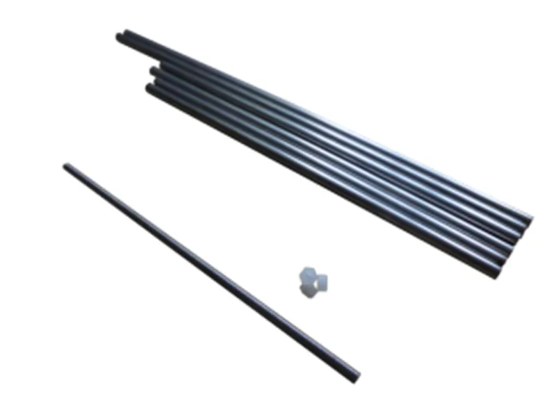
| CAD model of the mold (*.STL, *.CLI) | 3D printer | Sand-polymer mold | ||
Digital data make it possible to carry out an engineering analysis of a future product using modern design technologies, design and technological engineering analysis and computer simulation of the metal pouring process, which allows for quick adjustment of the design of castings, gating systems and foundry sand molds in the process of testing the casting technology, reducing allowances, reducing the weight of castings and improving their quality. Modeling the flow of liquid metal and its crystallization as part of the design process allows for digital iterations of the mold and core design before the actual pouring of the metal. By combining virtual modeling tools with 3D printing technology, the chances of successfully prototyping the desired Grade 6 casting can be maximized when the metal is first poured into the sand mold.
| Engineering analysis of the future product | ||
| Macroshrink | Microshrinkage | Pace. module |
|
| ||
| Liquid phase analysis | Flow Analysis | Temperature |
| Development of gating and feeding systems | ||
No size restrictions
The S-Max Pro sand 3D printer with two printing bins (1 hopper LSHV=1800×1000×700mm; 1260 l) has the maximum volume of the construction area, however, the technology allows printing large fragments of forms or simultaneous printing of many small prefabricated fragments that can be assembled immediately after printing.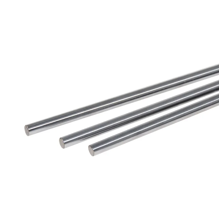
Lack of technological equipment and model production
The process eliminates the use of model equipment. The absence of the need to design and manufacture tooling allows you to reduce the time for CCI and the cost of products, the design of model tooling for which is extremely laborious or impossible. Significantly reduces the cost of organizing and maintaining model sites. The design of products is not limited by the possibilities of tool production. The absence of restrictions associated with the use of shaping pattern equipment makes it possible to design and manufacture cores and molds of any complexity and configuration, with 3D printing of undercuts and without molding casting slopes. The complexity of the entire cycle of design and technological preparation for the production of castings is reduced by 3-10 times. Due to the ability to quickly adjust the design of molds in the process of developing the casting technology, it is possible to reduce allowances, reduce weight and improve the quality of castings.
| No more slips! |
Hybrid production
| Binder Jetting does not compete with traditional casting technologies. The use of 3D printing in traditional technological chains provides additional economic benefits, time savings and increased production efficiency | |
| Figures show operations of the hybrid earth casting process: complex core tooling components are 3D printed and mounted in standard cast iron flasks for serial casting | |
Key Benefits of ExOne 3D Sand Printer
| | |
| Leader in new technologies | |
| ExOne (formerly ProMetal) has held the exclusive patent for the use of Binder Jetting in additive manufacturing since 1996 and has 's deep, versatile competencies in sand, metal, ceramic and composite 3D printing.  Since 2002, serial deliveries of 3D printers operating using BJ technology to the US and European markets. On the territory of the Russian Federation more than 10 additive machines manufactured by ExOne are operated, put into operation over the past 10 years. | |
| Complete design and design freedom | |
| The absence of the need to design and manufacture tooling can significantly reduce the manufacturing time and cost of products. And since changing the design of an object does not require to create new tooling, the use of 3D printing allows quick adjustment of the design of gating-feeding systems and foundry sand molds in the process of testing the casting technology, reducing allowances, reducing the weight of castings and improving their quality. | |
| High speed printing - d about 125 l/h. | |
| The fastest metal and ceramic 3D printer X1 160Pro has printing speed over 10,000.00 cm 3 /hour, which allows the use of ExOne 3D printers for mass production | |
| Printing accuracy +-0.3mm | |
| The printing error in the finished product lies within + -0.3mm | |
| Fully open sand loading system | |
| ExOne 3D printers are completely open to use by any materials, including domestic production, however, in most cases, it is strongly recommended to test the customer's material by ExOne methodologists before purchasing. | |
| Fast growing company | |
More than 350 printers have been put into operation all over the world, including more than 10 pcs. |
 (20 sec/layer)