3D printer settings
7 Key 3D Printing Slicer Settings You Need To Know
What is a Slicer?
As you may know, a slicer is a piece of 3D printing software that takes a digitized 3D model and converts it into printing instructions that your printer can then use to turn the model into a physical object.
In essence, the slicer takes the CAD model and “cuts” it into layers. Think of a series of 2D pictures stacked on top of each other to create a 3D model.
It then calculates how much material needs to be used for that layer, where the material should go and how long it will take.
It then converts all of the information for each layer into one GCode file which is sent to your printer. You set up the job and, voila! Sometime later you have a physical representation of the 3D CAD model.
As you can see, the slicer plays an integral role in helping turn your 3D ideas into reality. Therefore, how you use the slicer, specifically how you use the settings, is often a critical difference between printing success and failure.
In this article, we’re going to look at 6 key slicer settings that are common to all the major slicer programs. We’ll tell you what they’re for and we’ll explain how to use them to increase your chances of producing beautiful and useful objects each and every time you print.
Best 3D Printer Slicer Settings
1. Layer Height
Layer height is the 3D slicer setting that establishes the height of each layer of filament in your print. In some sense, layer height in 3D printing is akin to resolution in photography or videography.
When you choose a thicker layer height, your object will have less fine detail and the layers will be more visible. When you choose a thinner layer height, a higher level of detail is possible and your layers will tend to blend into one another.
However, keep in mind that the thinner you make the layer height, the more time it will take to print the object in question, since there will be more layers to print.
An object with less detail, on the other hand, will print faster with a thicker layer height. It will also have a less smooth surface. Thicker layer height is often chosen for making a prototype of an object, since detailing and surface texture usually doesn’t matter.
Read more: best layer heights in 3D printing, and how layer height affects your results
2. Shell Thickness
A shell is the outer wall of a designed object. Shell thickness refers to the number of layers that the outer wall will have before infill printing will begin. The higher the setting is for shell thickness, the thicker the outer walls of your object will be.
Obviously, thicker walls make for a sturdier object, so if strength is a quality that you’re after, it pays to increase the shell thickness appropriately.
Obversely, delicate or decorative designs do not usually require strength. Increasing the shell thickness in these instances provides no real benefit and will likely distort the design of the object being printed.
3. RetractionThis setting is used to pull the filament slightly back into the print head during times when the head is traveling from one print point on an object to another.
This stops the filament from leaking out of the print nozzle and leaving strings of material across otherwise empty space.
If your CAD design has a discontinuous surface, your slicer program should automatically enable the retraction setting.
4. Fill Density
Fill density, or infill, is a measure of how much material will be printed inside the outer shell of the object in question. Fill density is usually measured as a percentage of the whole, as opposed to a unit of measure.
This means that if 100% fill density is selected, the printed object will be solid, with no empty space inside the outer shell. Likewise, if 0% is selected, the printed object will be empty inside. Fill density is used to conserve filament while printing and speed up printing times.
However, an object with more infill will be stronger and heavier than an object with less infill. Therefore, if either of these properties will benefit the printed object, consider increasing the fill density as needed.
Read more: optimum infill settings
5. Print Speed
Print speed is how fast the print head travels while extruding filament. Therefore, optimal speed depends on the object you are printing and the filament material that you are using to fabricate the object.
In general, simple objects with less detail can be printed faster without complication.
On the other hand, more complex objects with more detail will benefit from a slower print speed. Print speed can also affect adhesion to the print surface, cause under or over extrusion and other problems. Because of this, it pays to experiment with your print speed to see what works best for the job you’re printing.
6. Bottom/Top Thickness
This setting determines how much material will be laid down before the infill printing starts and how much material will be laid down after the infill printing is finished. The thickness of the material at the top and bottom of your object is important for two reasons.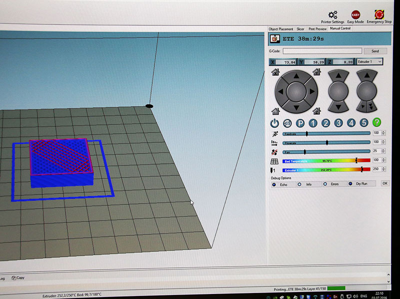
First, thicker material at the bottom of your object will provide a stronger and more stable base. Second, thicker material at the top of your object will prevent sagging and pillowing from occurring when the top layer of material is laid down over the infill lattice.
This is especially important if you are using a smaller layer height setting. In such a case, the thinness of the layer can be insufficient to completely cover the infill unless multiple layers are used.
Setting the bottom/top thickness to be 6 to 8 times greater than the layer height ensures that there is enough material being laid down to adequately cover the infill without complications.
7. Spiralize – Smooth out the Z Scar
If you’ve printed an object and on one side there appears a vertical scar all the way up the print, this is called a Z scar (also known as a “zipper”). It’s formed from the printer starting and stopping each layer at this point.
This scar can be unsightly, and on very thin prints also significantly weaken the structure.
To remove the Z scar, you’re going to need to activate the Spiralize feature in your slicer. This makes the outer layers print in a continuous line all the way up the print, meaning there’s no definitive stop and start point and therefore no scar formed.
To activate Spiralize feature and remove the vertical scar:
In Cura, it’s called the “Spiralize outer contour” feature, in other slicers it may be slightly different. Make sure this option is checked when you convert your STL file to a Gcode.
It is useful to remember to only change one slicer setting at a time so that you can see the effect that the change is having on your print. If the change is beneficial, write down the change that was made and proceed, if necessary, to change another setting.
Changing multiple settings at the same time can cause chaotic conditions and a positive effect can be canceled out by one or more negative effects.
It may be useful when planning prints to know the length of filament on each size spool for various materials and sizes.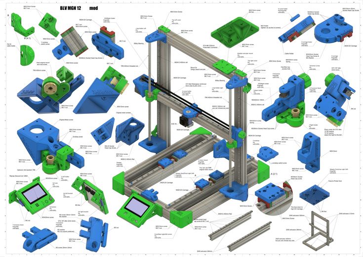 To help with this, we’ve created this filament calculator.
Other articles you may be interested in:
- Best 3D slicers
- Best resin 3D slicers
- Best slicers for Ender 3
FDM 3D Printer Settings and What They Do
3D printing has never been more accessible, with machines available that hit every price point and skill level. This has caused many people to flock to this relatively new hobby, jumping in headfirst without understanding the frustration and sorrows it can bring.
Of course, while 3D printing can be difficult, it is always well worth the effort that you put into it. Learning is a big part of taking something like this on, but you don’t have to go through it alone. To get you started with the fundamentals of using a 3D printer slicer, this article will be exploring the different settings that come with popular slicer programs for FDM printers.
What Is an FDM 3D Printer?
FDM stands for fused deposition modeling, and this is the most commonly used technology for 3D printing at home.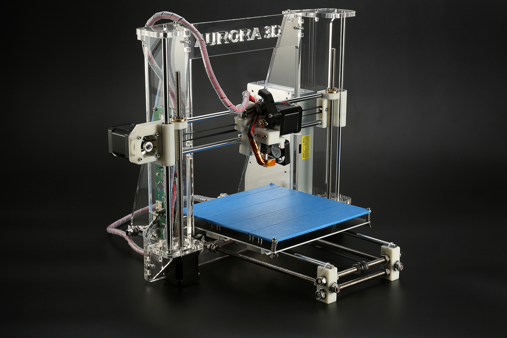 If your 3D printer uses spools of filament, rather than resin, the odds are that it is an FDM printer. Printers like this lay melted plastic out with extreme precision, usually with a build plate, gantry, and extruder/hotend. This is the type of 3D printer that this article applies to.
All of the settings below are shown assuming that you have loaded a file into your slicer and are on the main screen.
Related: How to 3D Print for First Timers and Beginners
Nozzle & Bed Temperature
FDM 3D printers use materials called thermoplastics to create objects. PLA, ABS, and PETG are just a few examples of these plastics, and they all have different melting points. Your nozzle temperature needs to be set to the temperature that matches the material you are printing with, and just a few degrees of difference can give you wildly varied results.
PLA, for example, usually prints well between 180 and 200°C, while ABS is good at 230 to 250°C.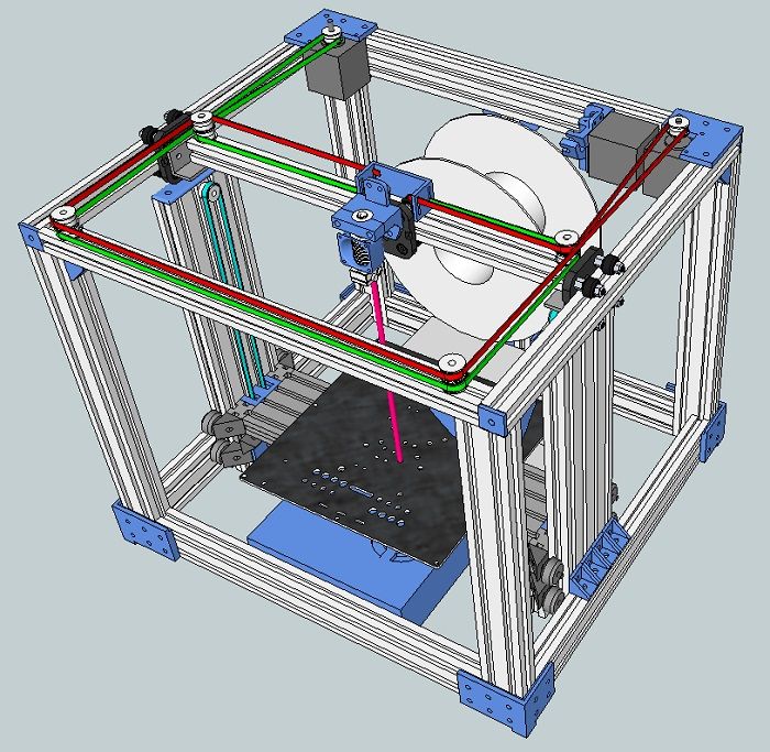 You may have to experiment with different temperatures to get the best results.
Bed temperature isn’t as important as nozzle temperature, but it can still make a difference. Having a bed at the right temperature will help materials to adhere to your build plate, while also helping to prevent issues like warping and elephant’s foot. Materials like PLA can work without a heated plate, but ABS can benefit from bed temperatures exceeding 80°C.
- Cura: Print Settings > Custom > Material
- Slic3r: Settings > Filament Settings > Temperature
- Simplify3D: Edit Process Settings > Show Advanced > Temperature
- FlashPrint: Print > General > Temperature
Layer Height
Layer height is the thickness of each layer of plastic that is placed on the bed during printing. Lower layer heights result in higher-resolution models and slower print times, whereas higher layer heights will lower both quality and time. You have to make sure that your layer height works with the nozzle you are using, though most slicers will warn you if you go too big or small.
The first layer of any print is the most important, and this is why most slicers offer the option to set a separate height for it. Having a thicker initial layer can help with bed adherence while also strengthening the base of the model.
- Cura: Print Settings > Custom > Quality
- Slic3r: Settings > Print Settings > Layers and Perimeters
- Simplify3D: Edit Process Settings > Show Advanced > Layer
- FlashPrint: Print > General > Layer
Related: How to Fix Auto-Leveling Issues on the Anycubic Vyper
Print Speed
Print speed is the speed at which your print head moves during printing.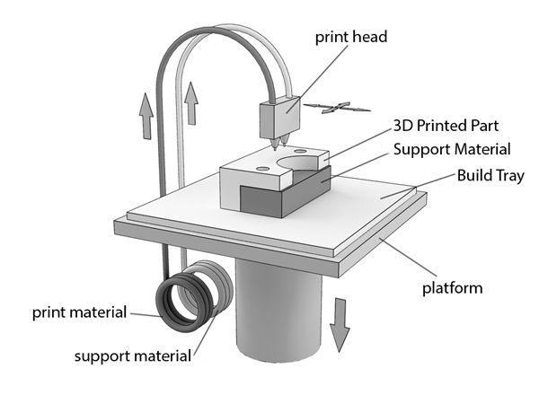 Raising the print speed will make printing faster, though it can also hurt the quality of your print. Alongside this, though, certain materials require slower print speeds because of their qualities.
PETG, for example, is usually printed with a maximum speed of 30mm/s to account for oozing and stretchiness. PLA and ABS can quite happily run at 60mm/s or higher, but you can tweak settings like Exterior Speed to raise the quality of your finished print without compromising on print speed.
- Cura: Print Settings > Custom > Speed
- Slic3r: Settings > Print Settings > Speed
- Simplify3D: Edit Process Settings > Show Advanced > Speeds
- FlashPrint: Print > General > Speed
Retraction
Most modern FDM 3D printers use motorized extruders to retract the filament at certain points during printing. This helps to prevent oozing while the print head moves from place to place, along with giving the printer control over the flow of material coming out of the hotend.
Much like print speed, retraction settings are usually based on the material you are printing with. Stretchy materials like PETG and TPU require retraction speeds of between 30 and 80mm/s, along with retraction distances of 2 to 5mm. In contrast, PLA is good with a speed of 50mm and a distance of 0.5 to 1mm.
- Cura: Print Settings > Custom > Travel
- Slic3r: Settings > Printer Settings > Extruder
- Simplify3D: Edit Process Settings > Show Advanced > Extruder > Ooze Control
- FlashPrint: Print > General > Retraction
Infill & Walls
It’s rare to find a 3D printable file that needs to be made from solid plastic.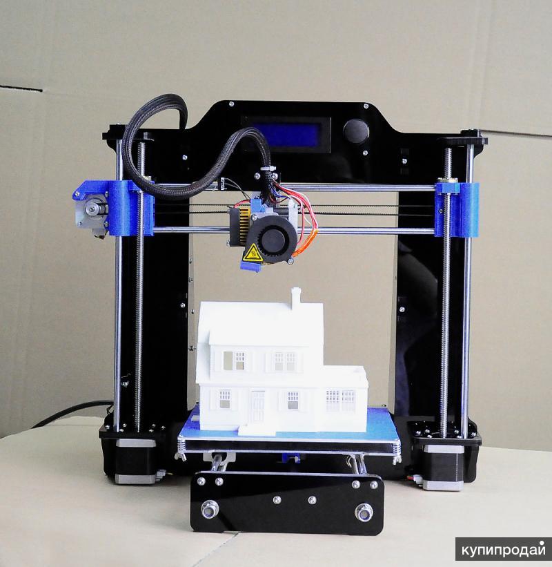 Instead, most prints are made with solid outer walls and infill that makes the part nice and strong without taking a lifetime to print. 10 to 20% infill is enough for the vast majority of prints, though you may want more if you want a piece to feel particularly solid. It is worth noting that solid infill doesn’t necessarily make a part stronger.
Alongside infill, you can also change the thickness of the outer layers of your print. Between three and five layers is usually enough to make a print strong, but this is something that can be tweaked to reduce the time it takes to complete your print. Overly thin walls can result in the infill pattern showing through.
- Cura: Print Settings > Custom > Infill/Shell
- Slic3r: Settings > Print Settings > Infill
- Simplify3D: Edit Process Settings > Show Advanced > Infill
- FlashPrint: Print > Infill
Supports
Supports are used to stop models from drooping when they are printed with overhangs. Most slicers can generate supports automatically, but you can alter the settings to make sure that you get the best results for your print. It’s worth reading about the different support options you have before you go ahead and change them too much.
- Cura: Print Settings > Custom > Supports
- Slic3r: Settings > Print Settings > Support Material
- Simplify3D: Edit Process Settings > Show Advanced > Support
- FlashPrint: Print > Supports and Main Screen > Supports
Additions
Most slicers are able to add additional parts to your print that are designed to help with bed adhesion and warping. This can be a great way to improve your prints with ease, but there are a few types available.
- Rafts: Your whole print sits on a bed when you use a raft, helping with bed adhesion.
- Brims: Brims wrap around the edge of your print, preventing the edges and corners from lifting.
- Mouse Ears: Mouse ears are circles that sit at each corner of your print, helping to keep the corners down.
- Wipe Towers: Wipe towers form around your print and allow your printer to wipe excess filament away.
Here’s where to find the relevant settings:
- Cura: Print Settings > Custom > Build Plate Adhesion
- Slic3r: Settings > Print Settings > Skirt & Brim/Support Material
- Simplify3D: Edit Process Settings > Show Advanced > Additions
- FlashPrint: Print > Additions
Cooling
Cooling fans are a vital part of your 3D printer.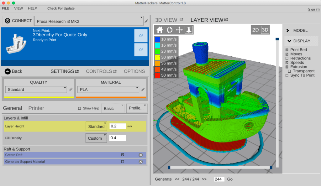 Many modern FDM printers have fans that are used to cool the part as it prints. This is great for materials like PLA and PETG, but it can be bad for materials like ABS that will warp thanks to temperature changes. You should almost always leave your general printer cooling on.
- Cura: Print Settings > Custom > Cooling
- Slic3r: Settings > Filament Settings > Cooling
- Simplify3D: Edit Process Settings > Show Advanced > Cooling
- FlashPrint: Print > Cooling
Z-Hop
As the last setting to look at, z-hop allows you to tell the printer to lower the bed or raise the print head when it moves around. This can prevent models from being knocked from the build plate before the print is finished.
- Cura: Print Settings > Custom > Travel
- Slic3r: Settings > Printer Settings > Retraction
- Simplify3D: Edit Process Settings > Show Advanced > Extruder > Ooze Control
- FlashPrint: Print > Others > Z-Hop
Learning to Use Your Slicer
Slicers are incredibly powerful tools that give you a lot of different options for your prints. This doesn’t mean that they are easy to use, though, and you still have more learning to do after this article to truly master the slicer you use.
It’s always worth keeping in mind that FDM 3D printers also need to be calibrated and maintained to work properly. This doesn’t take too much work, but the time you put into it can be well worth it.
Instructions for setting up all the mechanics of a 3D printer: from belts to speeds
The quality of the printed models directly depends on the mechanics of the printer, namely on its correct settings. Any elements of the printer wear out over time, so the printer must be set up at least once every 5-6 kg of printed filament. With the help of the short instructions described in this guide, you can quickly and easily set up the mechanics of your printer: belt tension, motor current, motor steps, acceleration, jerk and speed.
Mechanics includes
3D printers of any design always contain the same things: Axes and rails along which the elements of the printer move and motors with belts that set these elements in motion. In a classic printer design, there are at least 3 motors (one for each axis), 3 rails (one for each axis) and an electronics board that controls the motors. The latter can hardly be called part of the mechanics, but since it controls the engines, it also indirectly affects the quality of the model.
Printing defects due to mechanical problems
Before changing anything in the printer, you need to decide what exactly needs to be configured. Often defects are visible visually. Our blog has an article about most printing defects, which details the reasons for their occurrence. The following is a list of defects and what element of mechanics they are associated with:
-
Layer shifting - Belts, Motor current, Guides
-
Ringing - Guides, Speed
-
Incorrect model geometry - Guides, Motor steps, belts
As you can see, all the above problems do not interfere with the printing process itself, but the result leaves much to be desired. Sometimes mechanical errors can completely stop the printer from working. Therefore, it is better not to take the situation to extremes and, if any problems arise, immediately start checking and configuring the 3D printer.
How to save settings
To fix some defects, you need to change the printer software settings.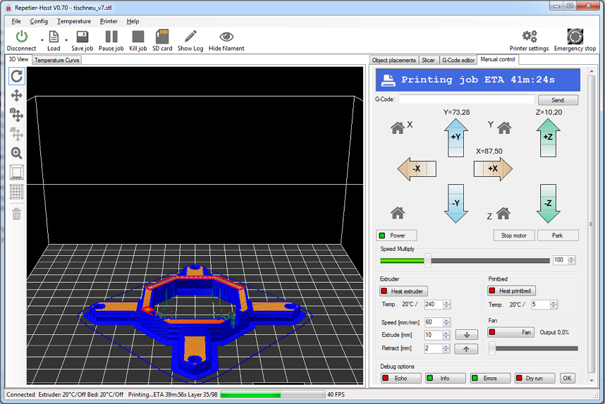 Therefore, before adjusting the mechanics, it is necessary to understand how to properly store the settings inside the printer. There are 3 ways to do this:
All settings are located in the corresponding menu of the printer
Depending on your firmware, this manual will indicate code sections for MARLIN firmware in the configuration.h file
We first enter the parameters into the printer and then store them in EEPROM - the internal memory of the microcontroller. Or paste all the necessary settings at the beginning of GCODE. To learn how to do this, read our article on working with GCODE and creating macros.
To save to EEPROM, you need to send the printer a command to change some value (which can also be inserted into the initial GCODE), and then send the M500 command (save the current settings to permanent memory). The EEPROM function must be enabled in the firmware, for this you need to remove two slashes in the line:
//#define EEPROM_SETTINGS
Whichever option you choose, you should be careful when using any commands.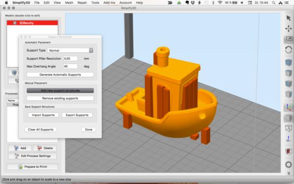 You will not be able to harm the printer in any way when changing the settings, but if you make a mistake, you will have to look for the cause of possible further problems for a long time.
Setup instructions
Now you can start setting up the printer itself. If you decide to set several parameters at once, then it is better to use the order of adjustments as in the article, since some of the settings are related to each other and if you use the wrong order, adjusting one element of the mechanics will override the settings of another element. For example, you should not adjust the motor steps before tightening the belts, as changing the length of the belts will change the “true” steps per millimeter of the motors. Also, before setting up, you must make sure that there are no backlashes in the printer frame, tighten all belts.
Belts
The first thing to start setting up the printer is the belts. They directly affect the geometry of the model and, when pulled too much, they cause a lot of problems: displacement of layers, changes in geometry, ripples. First you need to make sure the belt is intact. To do this, look at the entire belt, especially the areas where the belts bend. If the belt has outlived its usefulness, then you can see a section of the belt where the distance between the teeth has greatly increased and a metal wire (cord) is visible between them. This means that it's time to completely change the belt.
Broken belt with broken cords
If the belt is intact or you have already replaced it, then you can proceed to the next step. Depending on the design of your printer, you need to move the roller through which the belt passes. The tension should be such that the carriage or table moves effortlessly, but at the same time, when moving quickly, the belt should not slip the teeth on the motor gear. Adjust the tension of the belts on each axis of the printer using this method.
Tip: if your printer came with a belt tensioner in the form of a spring attached to the belt itself, remove it.
Due to the flexibility of this tensioner, printing defects will occur, such as protruding corners on the model. It is better to adjust the belt without using this tensioner.
Belt tensioner
Current motors
As we know from the school physics course, the power of the engine depends on the voltage and current strength. Since the voltage on all printer electronics is the same everywhere, the only thing that can be changed is the current on the motor. More precisely, it should be said the maximum current that the driver will supply to the motors. To change this limit, you need to climb inside the case and find the printer board. On it you will see the printer driver. We are interested in a small potentiometer on the driver itself (in the picture below it is indicated as a tuning resistor).
Potentiometer location example on driver
For adjustment, you will need a voltmeter and a small Phillips or flathead screwdriver.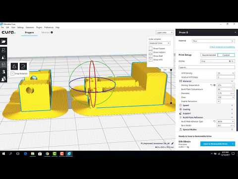 Before proceeding further, it is necessary to calculate the maximum current supplied to the motors. Different formulas are used for different drivers, the most popular ones will be listed in the table below:
| Driver name | Formula | Explanations |
| A4988 | Vref = Imax * 1.25 for R100 | To understand which formula to use, you need to find a resistor with the signature R100 or R050 on the driver. They are located next to the driver chip. |
| DRV8825 | Vref = Imax / 2 | |
| LV8729 | Vref = Imax / 2 | |
| TMC2208 TMC2100 TMC2130 | Vref = Imax * 1. | One formula for all drivers |
The value of the maximum current (Imax) depends on the motor controlled by the driver. This can be found in the engine specification or on the sticker on it. The following are the currents for the most popular motor models:
17HS4401 - current 1.7 A
17HS8401 - current 1.8 A
17HS4402 - current 1.3 A
Substituting the value into the formula, we get the Vref value for the maximum current supplied to the motor. But at this value, the engine will get very hot, so the resulting Vref value must be multiplied by 0.7. For example, for a motor with a maximum current of 1.5 A and a TMC 2208 driver:
Vref=1.5*1.41*0.7=1.48V
Now the resulting value can be used when configuring on the printer itself. To do this, disconnect the wires going to the motors, turn on the printer and place one voltmeter probe in the center of the trimmer, and the second probe to the negative terminal on the power supply (you can also use the negative terminal on the printer board and the contact on the driver, labeled as GND).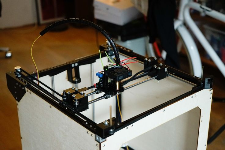 You will see some value on the voltmeter screen. Turn the trimmer clockwise to decrease the Vref value and counterclockwise to increase it.
Attention: you should not specify a Vref value higher than the maximum calculated for your engine! Otherwise, the engine will soon break down!
Once you have adjusted the value on the drivers, you can turn off the power to the printer, connect the motor wires, and put the case back together. This completes the driver setup.
Motor steps
When setting up motor steps, you will need a ruler. For convenience, you can use the program Repetier-Host. The adjustment for each of the three axes occurs according to the same algorithm:
-
Set the caret to zero coordinates (Autohome or G28)
-
Move the carriage some distance
-
We measure how far the carriage has traveled
-
We calculate the correct number of steps per millimeter using the formula:
True steps per millimeter = current steps per millimeter * reported distance / distance traveled
For example, if the printer was set to 100 steps/mm, we tell the printer to move 80mm and the printer travels 87. 5mm. Then the correct steps per millimeter would be 100 * 80 / 87.5 = 91.42 steps/mm. For the convenience of measurements, you can fix a ruler on the table, and a thin object, such as a needle or pin, on the carriage. Then it will be possible to accurately measure the distance traveled. The extruder uses a partially different algorithm to measure distance:
-
Inserting plastic into the extruder
-
Cut it right at the outlet
-
We give the printer a command to stretch the plastic a certain distance (at least 100 millimeters)
-
Cutting plastic again
-
We measure the length of the resulting piece of plastic
-
We use the formula from the previous algorithm
Next, the settings data must be inserted into the firmware in the line:
#define DEFAULT_AXIS_STEPS_PER_UNIT {X,Y,Z,E0}
X,Y,Z and E0 should be replaced by the steps per millimeter for each of the axes, respectively. Otherwise, you need to insert this line into the initial GCODE:
M92 Ennn Xnnn Ynnn Znnn
Instead of nnn in each of the parameters, you must substitute the steps per millimeter for each axis. If you want to adjust the steps only for not all axes, then you can remove unnecessary parameters.
Acceleration
This parameter is responsible for the rate of change of speed. That is, how fast the printer will change its speed. This affects the nature of the movement of the hot end relative to the table. If the acceleration is too small, then the printer will print slowly, if it is too large, then the outer surface of the model will have visual defects: fading waves will be visible near each of the corners, as in the picture below.
To set up acceleration, you need to follow simple steps:
-
Cut a model of a standard test cube with a wall thickness equal to one nozzle diameter, without filling and top layers, bottom 2-3 layers;
-
Open GCODE file in notepad;
-
Find the G28 command at the very beginning and insert the line data after it:
M201 X5000 Y5000
M204 P500 T500
-
Save the changes, print the model according to the received GCODE and note at what parameters P and T it was printed;
-
Open the same GCODE file and change the P and T values on the second line, adding 500 to each;
-
Repeat steps 4-5 at least 3 times;
As a result, you will get several test cubes, some of which will show waves at the corners. Choose the cube that is printed with the highest P and T parameters, but that no waves are visible on it. The number in parameter P will be the desired acceleration value. To save this value, you need to find 2 lines in the firmware:
#define DEFAULT_MAX_ACCELERATION {X,Y,Z,E0}
#define DEFAULT_ACCELERATION {nnn}
Instead of X and Y, you should put an acceleration twice as high as found earlier. And instead of nnn, you need to put the acceleration value found earlier. Otherwise, you need to insert a line in the initial GCODE:
M204 Pnnn Tnnn
In the parameters P and T, you need to put the value of the found acceleration. After that, the acceleration setting can be considered complete.
Jerk
A jerk indicates the speed with which to start accelerating. It affects the model in a similar way as acceleration: it creates ripples around the corners of the model. But it also increases the protrusion of the corners if the jerk is too small. The jerk setting is also similar to the acceleration setting:
-
Cut a model of a standard test cube with a wall thickness equal to one nozzle diameter, without filling and top layers, bottom 2-3 layers.
-
Open GCODE file in notepad
-
Find the G28 command at the very beginning and insert the line data after it:
M205 X5 Y5
-
Save the changes, print the model according to the received GCODE and note at what X and Y parameters it was printed
-
Open the same GCODE file and change the X and Y values on the second line, adding 2 to each
-
Repeat steps 4-5 at least 3 times
As a result, you will get several cubes. Find a non-rippled cube printed at the highest X and Y settings. This will be the jerk value for your printer. To save them, you need to find the line in the firmware:
#define DEFAULT_XJERKnnn
#define DEFAULT_YJERKnnn
It is necessary to substitute the jerk values for the X and Y axes, respectively.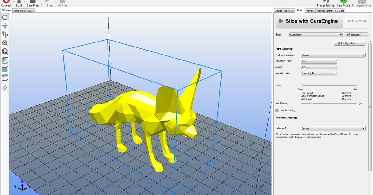 Otherwise, you need to substitute the command in the starting GCODE:
M205
Instead of nnn, you need to substitute the jerk value found earlier. This completes the jerk setting.
Speed
In fact, there are many different speed parameters, the values \u200b\u200bof which vary greatly. Let's take a look at the main ones:
This parameter is responsible for moving the nozzle without extruding plastic. The value is in the range from 80 to 120 mm/s. Limited only by the maximum speed at which the motors can rotate. Does not affect the model
This speed is important because it indirectly affects the adhesion of the model to the table. Usually lies between 15 and 30 mm/s
-Print speed of inner walls
Usually set to about 60 mm/s, it only affects the strength of the model. Depends on the maximum amount of plastic that the extruder can push through the nozzle
-Speed of printing outer walls
Usually about half the printing speed of the inner walls (30 mm / s).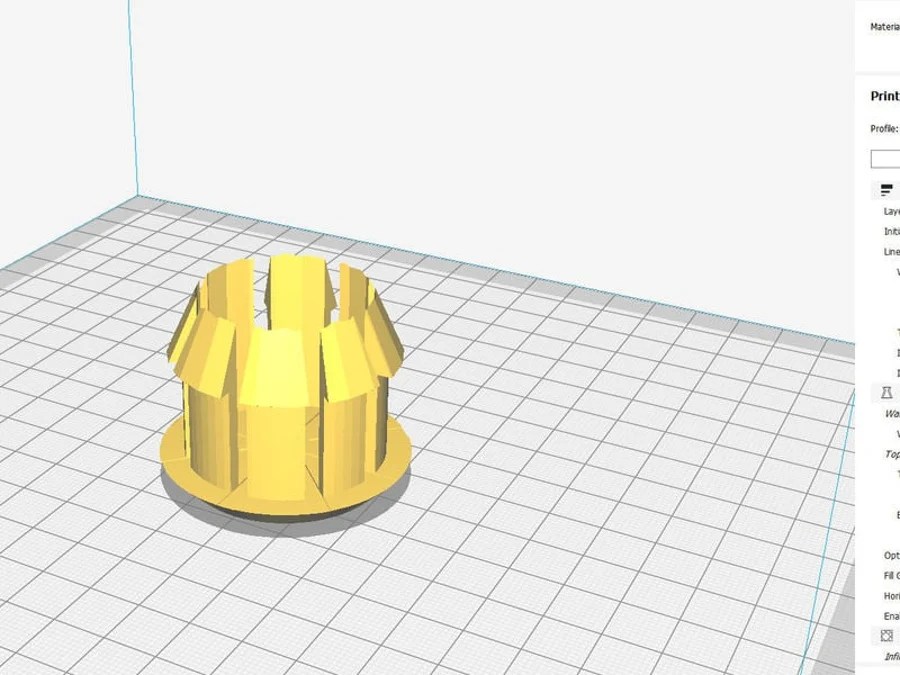 It affects not only the strength of the model, but also the appearance: the lower this speed, the smoother the walls will be.
The standard value is 80 mm/s, it only affects the strength of the model
Usually set from 20 to 40 mm/s, the quality of the upper layer of the model depends on it: the lower the value, the smoother the cover.
All of the above parameters are selected experimentally. Usually there is a simple rule: higher speed - lower quality. Therefore, do not try to find the ideal value for all situations. It is better to find values for fast printing, quality printing, and an average that will be used for most models.
Check settings
The last step in setting any of the above parameters will be to check the result. If you have written parameters in firmware or saved them in EEPROM, you can use the M503 command. It will display all printer settings on the computer. To test the settings in practice, you can print several test models:
Classic Benchy
Simple calibration cube
Calibration cat
On each of the above models, defects will be clearly visible, if they still remain after the mechanics are adjusted.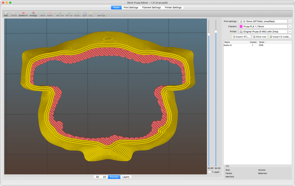
3D printer problems and settings, how to improve the quality of 3D printing
Problems and settings of a 3D printer, how to improve the quality of 3D printingAll reviews Lessons Interesting Wiki 3D Models Problems Reviews Video
12/09/2021
Lessons
Direct Feed vs. Bowden Bowden: What's the Difference and Which is Better?
Direct and Bowden extruder: what is the difference and which is better?...
10/28/2021
Lessons
The price of plastic for a 3D printer why are they expensive? It's just plastic!
To maintain constant, stable and better quality, an industrial...
10/28/2021
Tutorials
Practical guide for printing gears on a 3D printer
This material is a general guide for designing and printing on...
10/28/2021
Lessons
Meshmixer - tutorials, lessons, video instructions
If you haven't used Meshmixer before, you might also be interested...
10/28/2021
Lessons
Raft "Rafts", Brim "fields" and Skirt "skirts" - why they are needed and how to use them in 3D printing
Raft "Rafts", Brim "fields" and Skirt "skirts" » – In the community...
10/28/2021
Lessons
How to unravel a spool of filament if it gets tangled or knots
A terribly tangled spool of filament can completely stop any printing process.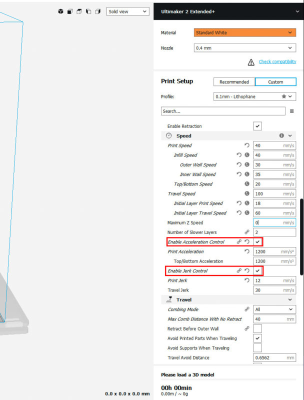 ..
..
10/28/2021
Tutorials
How to dry PLA, ABS and Nylon filament if the plastic has absorbed moisture, here's how to save a wet spool
Moisture from the air can easily destroy your 3D printing filament,...
10/28/2021
Lessons
PETG vs PLA: What's the difference? We explain on the fingers
PETG, and PLA are plastics of the polyester group. Like...
10/28/2021
Tutorials
5 Easy Tips for PETG 3D Printing and 3D Printer Settings
How to succeed in PETG 3D printing? Here are our five simple tips...
10/28/2021
Lessons
Carbon Fiber for 3D Printer
Recently, a number of 3D printing material manufacturers announced that...
1 2 3 … 6
Request a call back
Telephone
By clicking on the button, you agree to the privacy policy
Item added to cart
Go to cart
Product added to comparison
Compare products
Cannot compare more than 4 products
Invoice or quotation request
Organization name:
Your e-mail
Your phone
Name of contact person:
Legal address:
Comment:
By clicking on the button, you agree to the privacy policy of
Goods on the way, find out when the delivery is
Your name:
Your e-mail
Your phone
By clicking on the button, you agree to the privacy policy of
Contact us
How to call
By phone +7(495)155-45-19.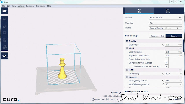 Your call will be answered by an answering machine. We won't call back if you don't speak up. Each request is processed, we contact clients in accordance with requests. Prepare the information you want to report, send it to the answering machine and we will call you back. We kindly request: do not be silent and do not hang up, this is just an answering machine. 🙂 Other most effective ways to get in touch:
- Write to Telegam @techno3dru
- Write to Whatsapp +74951554519
- Write Email [email protected]
Is the product in stock
On the product page, under the product name, there are 3 statuses:
- In Stock - We have this item in stock. Make a purchase with the Buy button.
- Pre-order - goods on the way, delivery soon. Find out about delivery times by clicking on 'Delivery times' or make a purchase using the Buy button.
Learn more