3D printer scheme
CREATE Education Loan Scheme | CREATE Education Project
We want to inspire and empower all young people to be creative, innovative and develop skills for the future by providing cutting-edge technologies to teachers and educators.
CREATE Education’s Mission
Accessibility is at the core of CREATE Education. We know that before embedding new technologies, teachers and educators want to be sure that they are easy to use, quick to set up, and engaging to their pupils.
That is why we offer a range of 3D printing, scanning, and forming technologies on our loan scheme. Our Loan Scheme means that you can trial these technologies within your school or organisation for a period of 5 weeks, whilst allowing you to complete projects and measure real results.
The 3d printer was amazing. I could not believe that I could design something online and then 45 minutes later it was in my hands. It’s like magic!
Student Quote
What can I loan?
You can loan:
- Dremel 3D45 Printer
- Ultimaker 2+ Connect 3D Printer
- Mayku Vacuum Former
- Einscan 3D Scanner
Along with the loan of the Dremel 3D45 or Ultimaker 2+ Connect, you will also get a free roll of filament, meaning that you can get to work on your project straight away, without paying out any more money.
If you loan a Mayku Vaccuum Former, individually or as part of a bundle, we will provide you with some sheets to get you started.
Apply Now
Having the 3d Printer in the school provided the pupils with a real sense of awe and wonder. They saw how a design online can be sliced and printed into a 3d model. Staff and pupils all enjoyed seeing the printer in action and loved having something purposeful from the experience!
Mr Hibble, Mellor Primary School
Our Loan Scheme is very popular and although we have several 3D Printers, 3D Scanners, and Vacuum Formers available to support the scheme, we may not have a machine available immediately. If you are planning to trial this technology through a future project, please contact us so that we can advise on availability and schedule a potential date for the loan period. If you have any questions regarding the loan scheme or if you require the printer for a longer or shorter time, please contact Jess Perry on 01257 01257 228393 or email j. [email protected].
Loan Bundles
You can loan our technology items individually, but for no extra cost to your organisation, we offer a loan bundle whereby you can loan a Mayku FormBox and 3D Printer together for the 5 week period, allowing you to unlock the full potential of these amazing technologies.
When you apply, just check the loan bundle option to reserve your Mayku FormBox and 3D printer together.
Apply Now
We cannot recommend the the CREATE Education Project highly enough! The children in our primary school have benefitted from learning real-life skills that have helped to increase engagement in STEM across the board from boys and girls to high attainers and low. We’ll definitely be wanting to be part of this again for future cohorts and would urge other schools to take part too!
Mr Pheby, Primary Teacher.
Here to fully support you
As well as your loan machine and consumables (if it is a 3D printer) you will also receive full support to get you started.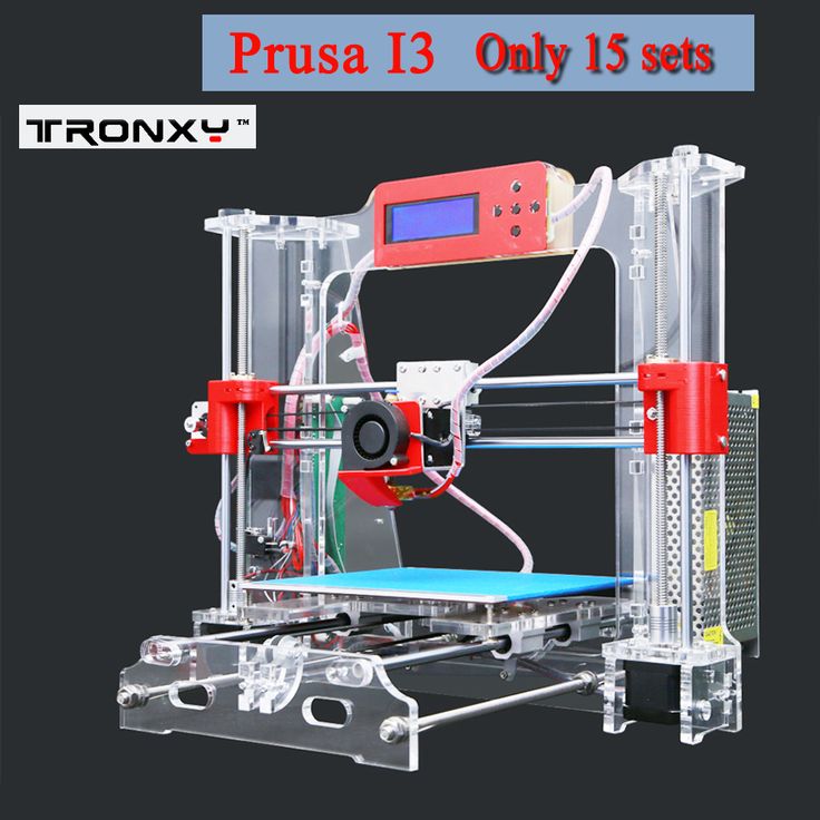 This includes:
- A virtual ‘set up’ session with a CREATE Education staff member to take you through the machine and ensure it is working.
- Access to a virtual ‘project ideas’ session delivered by a CREATE Education staff member to help provide practical ideas in how to get the most out of having the machine and your loan.
Their loan scheme for 3d printers is simply phenomenal and has been a great help to my organisation. I would definitely recommend it to anybody with an interest in 3D printing. From top to the bottom, the staff are truly amazing and are always willing to give advice/help as well as provide resources.
Nile Henry, Create Ambassador
How to apply
Follow these 3 simple steps below to reserve your loan machine today!
- Read the terms and conditions of the loan scheme. If you agree to these, fill in the online loan agreement form below.
- Once you have completed the online form, we will get back to you to confirm the details of your loan including key information such as:
- Start and end date when you will receive your machine.
- An opportunity to arrange a virtual 1:1 set up call with one of our support team to ensure your machine is working when it arrives.
- A link to an introductory webinar where our team member Sonya Horton will introduce you to the 3D printing process, the software and guide you through some exciting projects that you could use and incorporate into your delivery over the course of the 5 week loan with your young people.
- Further project ideas via our resources and blog for additional ideas.
- Arrange for the deposit to be paid to CREATE Education ahead of the loan period start date.
Apply Now
Terms and Conditions of the Loan Scheme
I understand that I must:
- Complete the Loan Scheme registration form in full and submit it.

- Arrange payment of the deposit and delivery charge (so we can ship to your organisation) – this must be received in advance of your loan scheme start date.
To ensure the refund of your deposit and to support our wider work in making 3D Printing and technologies accessible to all, we ask that the following be completed by your organisation.
- If you loan a 3D printer or scanner, you must provide a time for CREATE Education to meet with you and your Headteacher/SLT to discuss your experiences further and consider the permanent implementation of 3D printing/scanning into your organisation to ensure long-term access and sustainability for your young people.
- The machine must be returned in good condition by the return date outlined in your confirmation email.
- Complete the CREATE Education survey with participating young people – we can share the responses with you.
- Showcase your work by writing a case study which shares your experiences in your organisation and the outcomes achieved.
Once completed we shall arrange the refund of your deposit.
What to do once you have received your Printer
When your machine arrives, carefully un-package it and keep all packaging safe for return postage.
Create your projects and have fun exploring the capabilities of the 3D printer, 3D Scanner, or Vacuum Former with your young people.
If you have any technical problems contact our support team at [email protected] or call directly on 01257 276 116 option 2.At the end of your loan period, package up the machine in its original packaging and return it to us. We will send you an email in advance of this date as a reminder. Make sure you complete the case study and the surveys to get your deposit back!
Apply Now
Stereolithography (SLA) 3D Printing Guide
Stereolithography (SLA) 3D printing is the most common resin 3D printing process that has become vastly popular for its ability to produce high-accuracy, isotropic, and watertight prototypes and end-use parts in a range of advanced materials with fine features and smooth surface finish.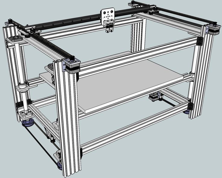
In this comprehensive guide, learn how SLA 3D printers work, why thousands of professionals use this process today, and how SLA printers can benefit your work.
White Paper
Looking for a 3D printer to realize your 3D models in high resolution? Download our white paper to learn how SLA printing works and why it's the most popular 3D printing process for creating models with incredible details.
Download the White Paper
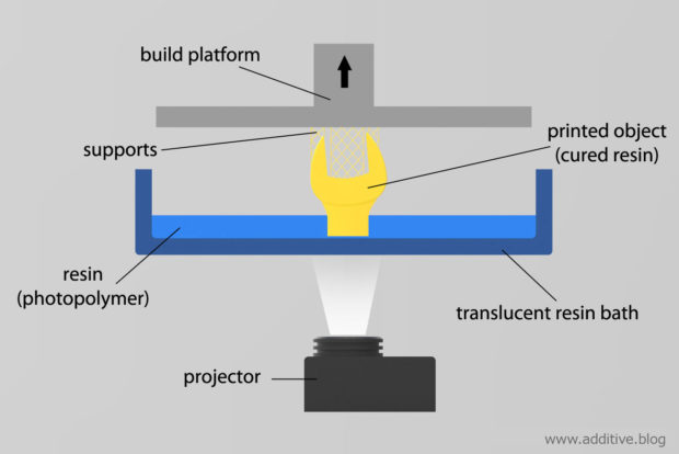
Stereolithography belongs to a family of additive manufacturing technologies known as vat photopolymerization, commonly known as resin 3D printing. These machines are all built around the same principle, using a light source—a laser or projector—to cure liquid resin into hardened plastic. The main physical differentiation lies in the arrangement of the core components, such as the light source, the build platform, and the resin tank.
Watch how stereolithography (SLA) 3D printing works.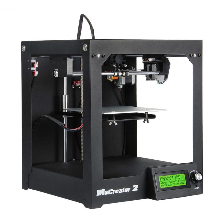
SLA 3D printers use light-reactive thermoset materials called “resin.” When SLA resins are exposed to certain wavelengths of light, short molecular chains join together, polymerizing monomers and oligomers into solidified rigid or flexible geometries.
A graphic representation of the basic mechanics of stereolithography (SLA) 3D printing.
SLA parts have the highest resolution and accuracy, the sharpest details, and the smoothest surface finishes of all 3D printing technologies, but the main benefit of the stereolithography lies in its versatility.
Material manufacturers have created innovative SLA resin formulations with a wide range of optical, mechanical, and thermal properties to match those of standard, engineering, and industrial thermoplastics.
Advancements in 3D printing continue to change the way businesses approach prototyping and production. As the technology becomes more accessible and affordable and hardware and materials advance to match market opportunities and demands, designers, engineers, and beyond are integrating 3D printing into workflows across development cycles. Across industries, 3D printing is helping professionals cut outsourcing costs, iterate faster, optimize production processes, and even unlock entirely new business models.
Stereolithography 3D printing in particular has undergone significant changes. Traditionally, SLA 3D printers have been monolithic and cost-prohibitive, requiring skilled technicians and costly service contracts. Today, small format desktop printers produce industrial-quality output, at substantially more affordable price points and with unmatched versatility.
Compare stereolithography 3D printing to two other common technologies for producing plastic parts: fused deposition modeling (FDM) and selective laser sintering (SLS).
Sample part
See and feel Formlabs quality firsthand. We’ll ship a free sample part to your office.
Request a Free Sample Part
See how to go from design to 3D print with the Form 3+ SLA 3D printer. This 5-minute video covers the basics of how to use the Form 3, from the software and materials to printing and post-processing.
Use any CAD software or 3D scan data to design your model, and export it in a 3D printable file format (STL or OBJ). Each SLA printer includes software to specify printing settings and slice the digital model into layers for printing. Once setup is complete, the print preparation software sends the instructions to the printer via a wireless or cable connection.
More advanced users may consider specifically designing for SLA, or taking steps like hollowing parts to conserve material.
After a quick confirmation of the correct setup, the printing process begins and the machine can run unattended until the print is complete. In printers with a cartridge system, the material is automatically refilled by the machine.
An online Dashboard from Formlabs allows you to remotely manage printers, materials, and teams.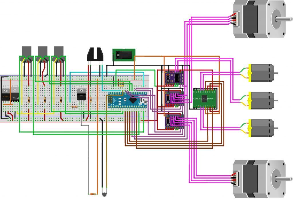
Once the printing is completed, parts require rinsing in isopropyl alcohol (IPA) to remove any uncured resin from their surface. After rinsed parts dry, some materials require post-curing, a process which helps parts to reach their highest possible strength and stability. Finally, remove supports from the parts and sand the remaining support marks for a clean finish. SLA parts can be easily machined, primed, painted, and assembled for specific applications or finishes.
Post-curing is particularly important for functional resins for engineering, and mandatory for some dentistry and jewelry materials and applications.
Webinar
In this webinar, Matt Lewis and Ricky Hopper walk you through an overview of the improved SLA line, and give a hands on demo of the new products.
Watch the Webinar Now
Engineers, designers, manufacturers, and more choose SLA 3D printing for its fine features, smooth surface finish, ultimate part precision and accuracy, and mechanical attributes like isotropy, watertightness, and material versatility.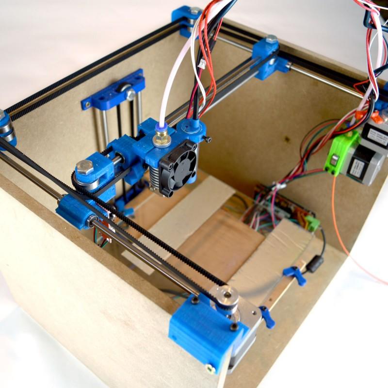
Because 3D printing creates parts one layer at a time, completed prints may have variations in strength based on orientation of the part relative to the printing process, with different properties in X, Y, and Z axes.
Extrusion-based 3D printing processes like fused deposition modeling (FDM) are known for being anisotropic due to layer-to-layer differences created by the print process. This anisotropy limits the usefulness of FDM for certain applications, or requires more adjustments on the part geometry side to compensate for it.
Read our in-depth guide about FDM vs. SLA 3D printers to learn how they compare in terms of print quality, materials, applications, workflow, speed, costs, and more.
In contrast, SLA resin 3D printers create highly isotropic parts. Achieving part isotropy is based on a number of factors that can be tightly controlled by integrating material chemistry with the print process. During printing, resin components form covalent bonds, but layer to layer, the part remains in a semi-reacted “green state. ”
”
While in the green state, the resin retains polymerizable groups that can form bonds across layers, imparting isotropy and watertightness to the part upon final cure. On the molecular level, there is no difference between X, Y, or Z planes. This results in parts with predictable mechanical performance critical for applications like jigs and fixtures, end-use parts, and functional prototyping.
SLA printed parts are highly isotropic compared to those produced with fused deposition modeling (FDM).
Because they are isotropic, SLA printed parts like this jig from Pankl Racing Systems can withstand the variety of directional forces they undergo during high stress manufacturing operations.
SLA printed objects are continuous, whether producing geometries with solid features or internal channels. This watertightness is important for engineering and manufacturing applications where air or fluid flow must be controlled and predictable. Engineers and designers use the watertightness of SLA printers to solve air and fluid flow challenges for automotive uses, biomedical research, and to validate part designs for consumer products like kitchen appliances.
OXO relies on the watertightness of SLA printing to create robust functional prototypes for products with air or fluid flow, like this coffee maker.
Industries from dental to manufacturing depend on SLA 3D printing to repeatedly create accurate, precise components. For a print process to produce accurate and precise parts, multiple factors must be tightly controlled.
Compared to machined accuracy, SLA 3D printing is somewhere between standard machining and fine machining. SLA has the highest tolerance of commercially available 3D printing technologies. Learn more about understanding tolerance, accuracy, and precision in 3D printing.
The combination of the heated resin tank and the closed build environment provides almost identical conditions for each print. Better accuracy is also a function of lower printing temperature compared to thermoplastic-based technologies that melt the raw material. Because stereolithography uses light instead of heat, the printing process takes place at close to room temperature, and printed parts don't suffer from thermal expansion and contraction artifacts.
An example from the dental industry comparing a scanned component with the original CAD geometry, demonstrating the ability to maintain tight tolerances across an SLA printed part.
Low Force Stereolithography (LFS) 3D printing houses the optics inside a Light Processing Unit (LPU) that moves in the X direction. One galvanometer positions the laser beam in the Y direction, then directs it along across a fold mirror and parabolic mirror to deliver a beam that is always perpendicular to the build plane, so it is always moving in a straight line to provide even greater precision and accuracy, and allows for uniformity as hardware scales up to larger sizes, like Formlabs larger format SLA printer Form 3L. The LPU also uses a spatial filter to create a crisp, clean laser spot for greater precision.
The characteristics of individual materials are also important for ensuring a reliable, repeatable print process.
Formlabs Rigid Resin has a high green modulus, or modulus before post-curing, which means it’s possible to print very thin parts with precision and a lower chance of failure.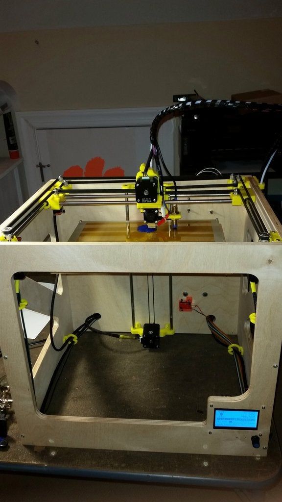
SLA printers are considered the gold standard for smooth surface finish, with appearances comparable to traditional manufacturing methods like machining, injection molding, and extrusion.
This surface quality is ideal for applications that require a flawless finish and also helps reduce post-processing time, since parts can easily be sanded, polished, and painted. For example, leading companies like Gillette use SLA 3D printing to create end-use consumer products, like 3D printed razor handles in their Razor Maker platform.
Leading companies like Gillette use SLA 3D printing to create end-use consumer products, like the 3D printed razor handles in their Razor Maker platform.
Z-axis layer height is commonly used to define the resolution of a 3D printer. This can be adjusted in between 25 and 300 microns on Formlabs SLA 3D printers, with a trade-off between speed and quality.
In comparison, FDM and SLS printers typically print Z-axis layers at 100 to 300 microns.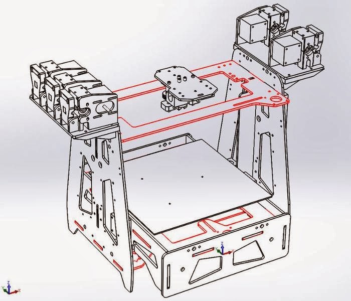 However, a part printed at 100 microns on an FDM or SLS printer looks different from a part printed at 100 microns on an SLA printer. SLA prints have a smoother surface finish right out of the printer, because the outermost perimeter walls are straight, and the newly printed layer interacts with the previous layer, smoothing out the staircase effect. FDM prints tend to have clearly visible layers, whereas SLS has a grainy surface from the sintered powder.
The smallest possible detail is also much finer on SLA, given 85 micron laser spot size on the Form 3+, in comparison with 350 microns on industrial SLS printers, and 250–800 micron nozzles on FDM machines.
While FDM 3D printed parts tend to have visible layer lines and might show inaccuracies around complex features, parts printed on SLA machines have sharp edges, a smooth surface finish, and minimal visible layer lines.
SLA resins have the benefit of a wide range of formulation configurations: materials can be soft or hard, heavily filled with secondary materials like glass and ceramic, or imbued with mechanical properties like high heat deflection temperature or impact resistance. Material range from industry-specific, like dentures, to those that closely match final materials for prototyping, formulated to withstand extensive testing and perform under stress.
Rigid 10K Resin is a highly glass-filled material for industrial parts that need to withstand significant load without bending, including applications like injection molding.
In some cases, its this combination of versatility and functionality that leads to companies to initially bring resin 3D printing in-house. After finding one application solved by a specific functional material, it’s usually not long before more possibilities are uncovered, and the printer becomes a tool for leveraging the diverse capabilities of various materials.
For example, hundreds of engineers in the Design and Prototyping Group at the University of Sheffield Advanced Manufacturing Research Centre (AMRC) rely on open access to a fleet of 12 SLA 3D printers and a variety of engineering materials to support highly diverse research projects with industrial partners like Boeing, Rolls-Royce, BAE Systems, and Airbus.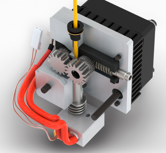 The team used High Temp Resin to 3D print washers, brackets, and a sensor mounting system that needed to withstand the elevated, and leveraged Durable Resin to create intricate custom springy components for a pick and place robot that automates composites manufacturing.
Engineers at the AMRC use a fleet of 12 SLA 3D printers and a variety of engineering materials to print custom parts for diverse research projects, like brackets for a pick and place robot (top), and mounts for sensors in a high-temperature environment (bottom).
Interactive
Need some help figuring out which 3D printing material you should choose? Our new interactive material wizard helps you make the right material decisions based on your application and the properties you care the most about from our growing library of resins.
Recommend Me a Material
SLA 3D printing accelerates innovation and supports businesses across a wide range of industries, including engineering, manufacturing, dentistry, healthcare, education, entertainment, jewelry, audiology, and more.
Rapid prototyping with 3D printing empowers engineers and product designers to turn ideas into realistic proofs of concept, advance these concepts to high-fidelity prototypes that look and work like final products, and guide products through a series of validation stages toward mass production.
Learn More
Manufacturers automate production processes and streamline workflows by prototyping tooling and directly 3D printing custom tools, molds, and manufacturing aids at far lower costs and lead times than with traditional manufacturing. This reduces manufacturing costs and defects, increases quality, speeds up assembly, and maximizes labor effectiveness.
Learn More
Digital dentistry reduces the risks and uncertainties introduced by human factors, providing higher consistency, accuracy, and precision at every stage of the workflow to improve patient care. 3D printers can produce a range of high-quality custom products and appliances at low unit costs with superior fit and repeatable results.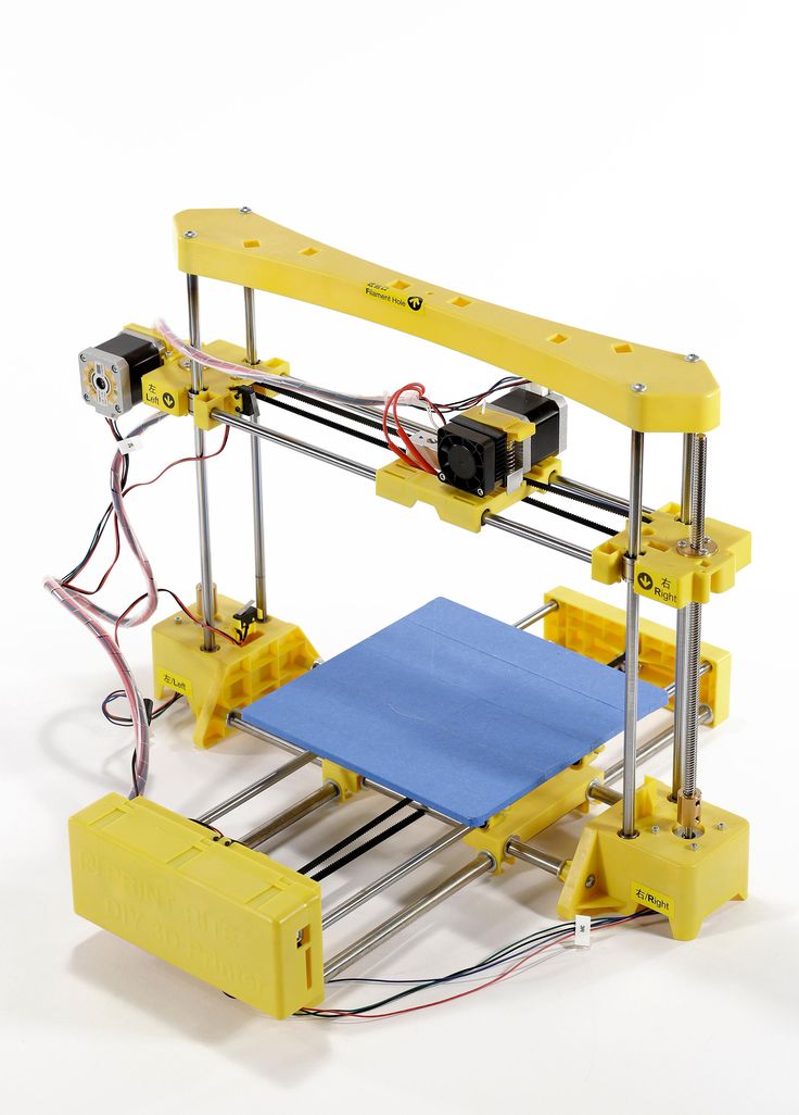
Learn More
Affordable, professional-grade desktop 3D printing helps doctors deliver treatments and devices customized to better serve each unique individual, opening the door to high-impact medical applications while saving organizations significant time and costs from the lab to the operating room.
Learn More
3D printers are multifunctional tools for immersive learning and advanced research. They can encourage creativity and expose students to professional-level technology while supporting STEAM curricula across science, engineering, art, and design.
Learn More
High definition physical models are widely used in sculpting, character modeling, and prop making. 3D printed parts have starred in stop-motion films, video games, bespoke costumes, and even special effects for blockbuster movies.
Learn More
Jewelry professionals use CAD and 3D printing to rapidly prototype designs, fit clients, and produce large batches of ready-to-cast pieces.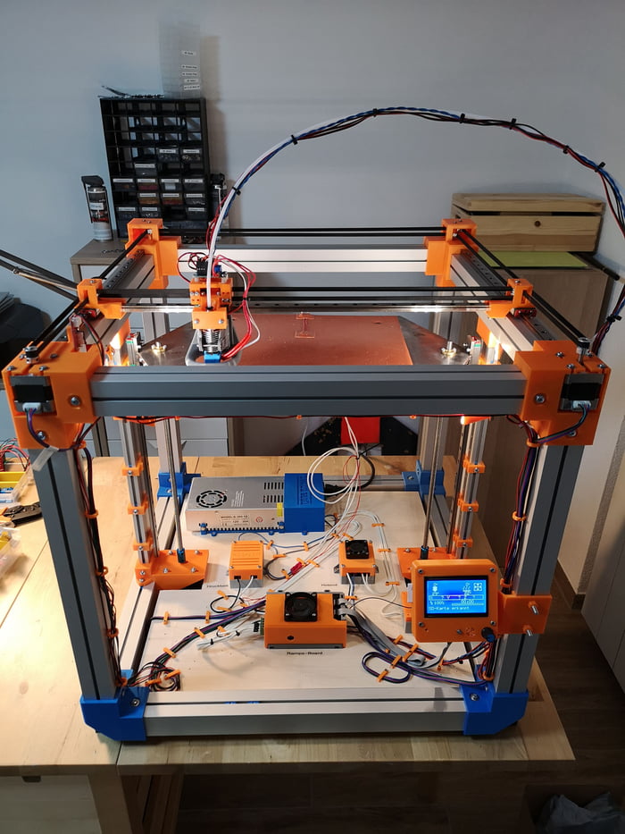 Digital tools allow for the creation of consistent, sharply detailed pieces without the tediousness and variability of wax carving.
Learn More
Hearing specialists and ear mold labs use digital workflows and 3D printing to manufacture higher quality custom ear products more consistently, and at higher volumes for applications like behind-the-ear hearing aids, hearing protection, and custom earplugs and earbuds.
Learn More
Many companies start using 3D printing via outsourcing to service bureaus or labs. Outsourcing production can be a great solution when teams require 3D printing only occasionally, or for one-offs that require unique material properties or applications. Service bureaus can also provide advice on various materials and offer value-added services such as design or advanced finishing.
The main downsides of outsourcing are cost and lead time. Often, outsourcing is a gateway to bringing production in-house as needs ramp up.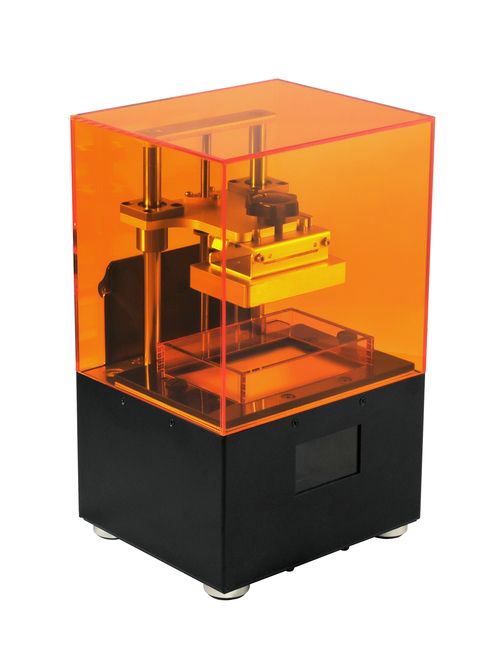 One of the greatest benefits of 3D printing is its speed compared to traditional manufacturing methods, which quickly diminishes when an outsourced part takes multiple days or even weeks to arrive. With growing demand and production, outsourcing also rapidly becomes expensive.
Because of the rise of affordable industrial-quality 3D printing, today, more and more companies choose to bring 3D printing in-house right away, vertically integrating into existing shops or labs, or in the workspaces of engineers, designers, and others who could benefit from translating digital designs into physical parts or who are involved in small batch production.
Small format, desktop SLA 3D printers are great when you need parts quickly. Depending on the number of parts and printing volume, investment into a small format 3D printer can break even within months. Plus, with small format machines, it’s possible to pay for just as much capacity as a business needs and scale production by adding extra units as demand grows. Using multiple 3D printers also creates the flexibility to print parts in different materials simultaneously. Service bureaus can still supplement this flexible workflow for larger parts or unconventional materials.
Interactive
Try our interactive ROI tool to see how much time and cost you can save when 3D printing on Formlabs 3D printers.
Calculate Your Savings
Fast turnaround time is a huge advantage to owning a desktop 3D printer. When working with a printing bureau, lead times, communication, and shipping all create delays. With a desktop 3D printer like the Form 3+, parts are in-hand within hours, allowing designers and engineers to print multiple parts in one day, helping to iterate faster and drastically reduce product development time and quickly test mechanisms and assemblies avoid costly tool changes.
Owning a desktop 3D printer results in significant savings over 3D printing service bureaus and traditional machining, as these alternatives rapidly becomes expensive with growing demand and production.
For example, to fulfill tight production deadlines, a process engineer and team at Pankl Racing Systems introduced SLA 3D printing to produce custom jigs and other low-volume parts directly for their manufacturing line. While in-house SLA was initially met with skepticism, it turned out to be an ideal substitute to machining a variety of tools. In one case, it reduced lead time for jigs by 90 percent—from two to three weeks to less than a day—and decreased costs by 80-90 percent.
| Cost | Lead Time | |
|---|---|---|
| In-House SLA 3D Printing | $9–$28 | 5–9 hours |
| CNC Machining | $45–$340 | 2–3 weeks |
| Outsourced 3D Printing | $51–$137 | 1–3 weeks |
Pankl Racing Systems significantly reduced lead times and costs by 3D printing custom jigs in-house.
With small format machines, it’s possible to pay for just as much capacity as a business needs and scale production by adding extra units as demand grows. Using multiple 3D printers also creates the flexibility to print parts in different materials simultaneously.
The Design and Prototyping Group at the University of Sheffield Advanced Manufacturing Research Centre (AMRC) runs an open-access additive manufacturing station with a fleet of 12 Form 2 stereolithography (SLA) 3D printers for hundreds of engineers working on diverse projects across the site.
Formlabs offers two high precision SLA 3D printing systems, a growing library of specialized materials, intuitive print preparation and management software, and professional services—all in one package.
To continue exploring SLA 3D printing, start with feeling the quality of SLA for yourself: Request a free sample 3D printed part in your choice of material to be mailed straight to your door.
Request a Free Sample Part
3D printing for the newest ones. From A to Z. Kinematics.
In this article, we will understand what 3D printing is and what the kinematics of 3D printers are.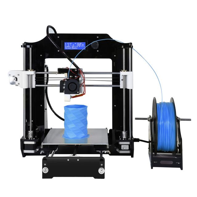
1. 3D printing. What does she taste like?
There are a lot of printing technologies, from FDM (FFF), which is used by more than 90% of printers on this portal, to SLA / DLP / LCD (with photopolymers) and SLS / SLM (powder sintering using powerful lasers)
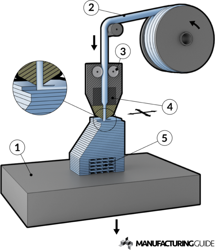
At the initial stage, we are interested in FDM - layer-by-layer deposition of a molten rod. The picture below shows the hot end (Hot end) - that part of the 3D printer extruder where the rod is melted.
The plastic rod is fed through the Teflon tube and radiator into the thermal barrier, and through it into the heating block. It melts there and exits through the nozzle. The nozzle has a certain diameter, which is marked on it.
It is often made of brass, as the material is inexpensive and easy to process. The accuracy of printing depends on the nozzle. The smaller the nozzle, the more threads fit into one mm.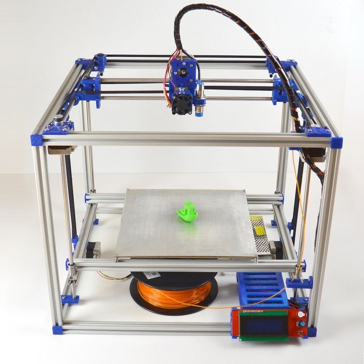
Heater and thermistor provide feedback for temperature control and regulation. That is, the voltage supply to the heater depends on what temperature the thermistor shows, and the processor compares it with the set one.
Next we see the heating block. A nozzle is screwed into it on one side, and a thermal barrier on the other.
The thermal barrier is used to minimize the heating of the plastic above the thermoblock.
[IMG]http://3d-makers.nethouse.ru/static/img/0000/0002/6151/26151635.2ofdbr37y8.W665.jpg[/IMG]
Most often made of stainless steel. It has a lower thermal conductivity than conventional, unalloyed steel. To prevent the rod from melting above the thermal block, a radiator is screwed on top of the thermal barrier and blown by a cooler. Everything is quite simple.
It is very common for melted plastic to leak through threads.
This means that the nozzle has not pressed the thermal barrier in the heater block. Therefore, when disassembling and assembling the hot end, we first screw the thermal barrier into the heating block, and then press it with a nozzle. If, when you twist the nozzle, there is a gap between the end of the nozzle and the heating block, then this is normal, the gap in order to press the thermal barrier with the nozzle.
In order to feed the bar at the right time and in the right place, a feeder is needed, that is, a bar feeder.
Sometimes it is performed combined with a hot end, and then this type of extruder (this is all together a hot end + feeder) is called a direct, that is, a direct feed, without tubes.
The same feeder is made separately, and the bar is fed through a fluoroplastic tube. Such a system is called bowden.
This is to lighten the moving part. In terms of positive aspects and disadvantages - each design undoubtedly has them.
Direct extruder:
1. Advantages:
a) More reliable due to fewer plastic feed connections;
b) Less picky about the materials it prints on, in particular rubber-based rubber is problematic to print on bowden extruders;
2. Disadvantages:
a) Large weight, due to this, during acceleration / deceleration, small ripples can be observed on the surface of the part;
b) Dimensions. They greatly affect the plot area. Let's say, like in the picture above, a direct with 4 colors would be very huge. And for Bowden, this is just right.
Bowden extruder:
1. Advantages:
b) The coil does not twitch after the model, otherwise, when the coil turns with the direct are entangled, we will get a skip of steps, since the carriage will pull the coil along with it.
2. Disadvantages:
a) Retract settings (pulling the rod back during idle movements so that the molten plastic does not ooze out of the nozzle while expanding) is more difficult, since the rod is smaller than the inner diameter of the tube, it tends to stretch;
b) It is more difficult than on direct to select all gaps in order to print with various flexible plastics.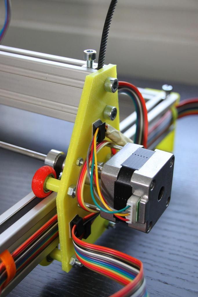 Everyone who says that printing on Bowden is impossible with flexible plastics is blatantly lying. I am typing. And quite successfully.
Now we go directly to the mechanics and its calibration.
Part 2. Mechanics. What, how and what pulls?
There is a very limited number of kinematic schemes for which the firmware is written, and which work out movements quite tolerably.
Consider everything, from the most common:
1. Design and kinematics from Joseph Pryusha (no need to read Prus, Prasha and so on, this is the name of a person, after all).
Movement along each of the axes is provided by its own independent motor. Movement along the Z axis (up and down) is provided with the help of 2 motors and with the help of a kinematic screw-nut pair. M5 studs are often used; recently, screws with trapezoidal threads have been increasingly installed.
Here is a trapezoidal screw.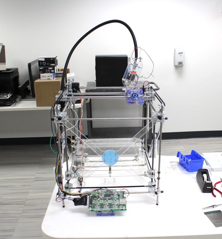 How studs with metric threads look I will not apply.
The only thing I will explain about moving along the studs and trapeziums is that for the production of trapeziums they take a calibrated rod and roll it between rollers at an angle. Get helical grooves. This method, a priori, gives better quality and step accuracy than building studs of far from the highest quality.
To connect 2 motors to one axle (and 1 connector) at the same time, the following scheme is used.
Connection in series, 2 wires soldered and the rest crimped. You can ignore the colors, the main thing is that the windings ring. A and B are windings, and 1 and 2 are terminals.
Advantages of this kinematics:
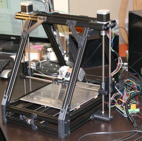
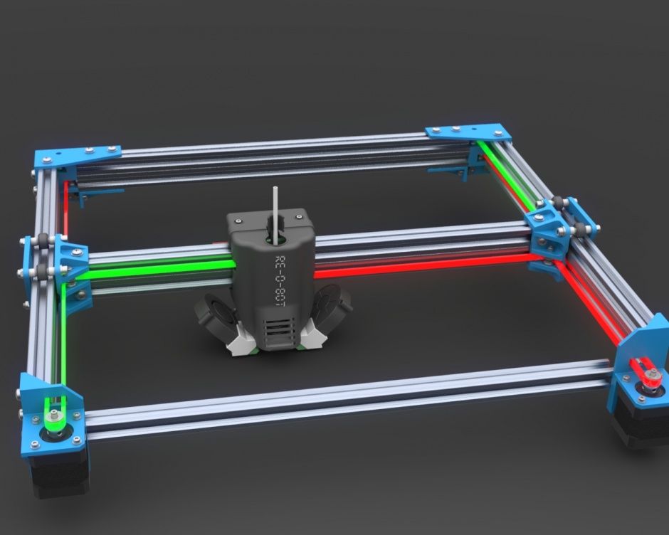
1) Independent movement of each axis. It is easy to catch to understand which axis skips steps. Kinematics migrated to printers from CNC milling, so many manufacturers make desktop milling machines on it, instead of an extruder they offer to install a laser for engraving or cutting, a spindle for milling boards, an extruder for chocolate or even dough to bake pancakes.
Pictured above is a ZMorph printer. It can be used as a printer (with one or two extruders), as an engraver (Dremel machine), as an engraving laser, and so on. A small presentation video.
Milling machine with this kinematics. I note that for milling it is necessary to use a screw-nut pair to move, and not belts, they are not designed for such loads.
Chocolate and pancake printers according to your design. It is worth noting that it is not recommended to use chocolates like Alenka or Babaevsky, since they already contain cocoa butter and during processing (melting and hardening) the result is unpredictable.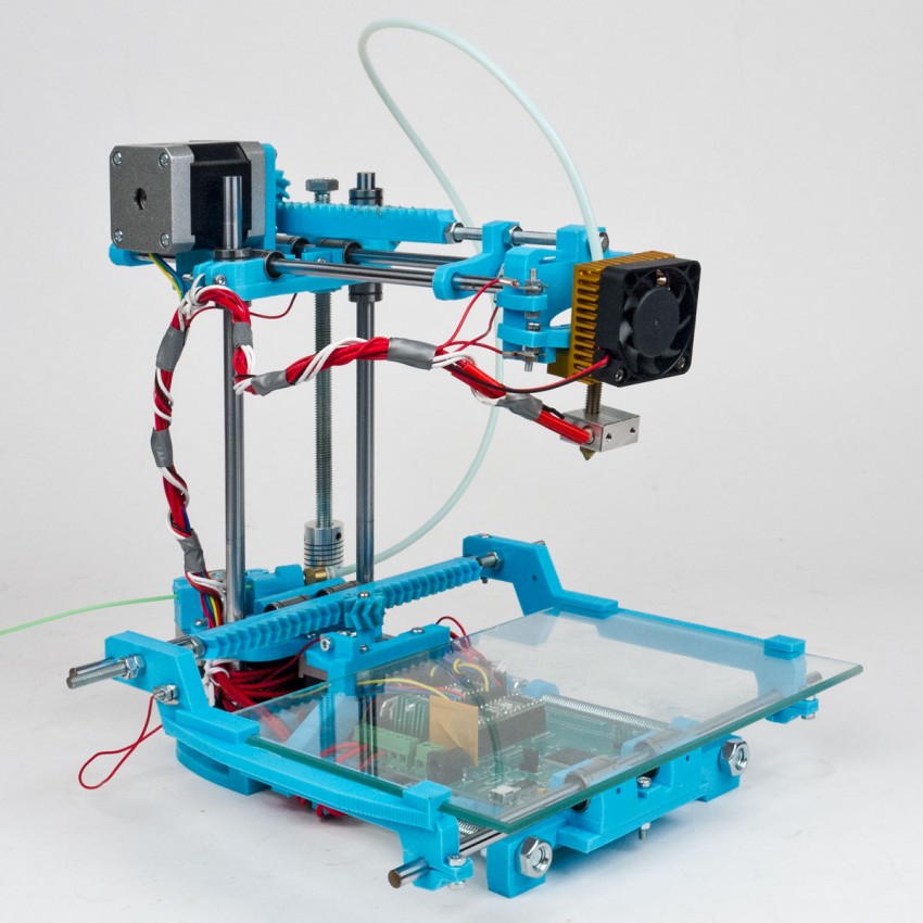 It is necessary to use chocolate in galettes, such as the Belgian Callebaut, as it does not contain cocoa butter, and must be added for the final filling. For this type of chocolate, each pack has a graph of its crystallization. It is desirable to take the oil in powder form. For more information, I recommend Google about tempering chocolate.
2) The kinematics are as easy as two fingers. Its very easy to assemble. Many even collect on old DVD drives.
3) Easily changed to suit your needs, the size of the extruder is also of little importance, as it protrudes forward and does not interfere with the movement of other parts. Many people put a second extruder, or make the nozzles swing so that the nozzles of one extruder do not remain on the part when printing with the second nozzle.
Therefore, for this kinematics, there are a huge number of extruder variations, for every taste, on a very famous site.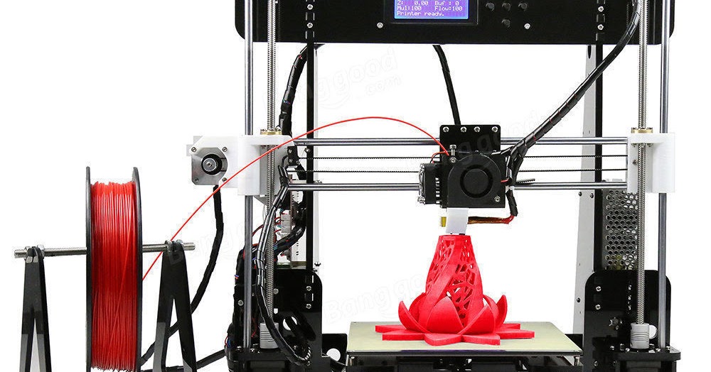
Disadvantages of this kinematics:
1) Complicated calibration. Yes, since the table 'jumps', it is difficult to print with high quality, because the part + table, with a sharp change in the direction of movement by inertia, tend to go further. Ugly print artifacts are obtained. And for high-quality printing, you need a small speed. In general, it all depends on the frame. My first printer was a Chinese pryusha. With acrylic frame.
Acrylic is not very hard. And as you know, the rigidity of the printer, like the CNC, is the most important thing. And it was possible to print more or less qualitatively at speeds of 40-50 mm / s. Then I transplanted it to a steel frame from MZTO.
And after that, without loss of print quality, I was able to print at speeds up to 100 mm / s.
2) Delamination. Due to the open case and the constantly moving platform, hot air, one might say, is constantly blown away, and by cooling the part excessively with drafts, we increase the already large shrinkage of nylons, abs and other capricious plastics.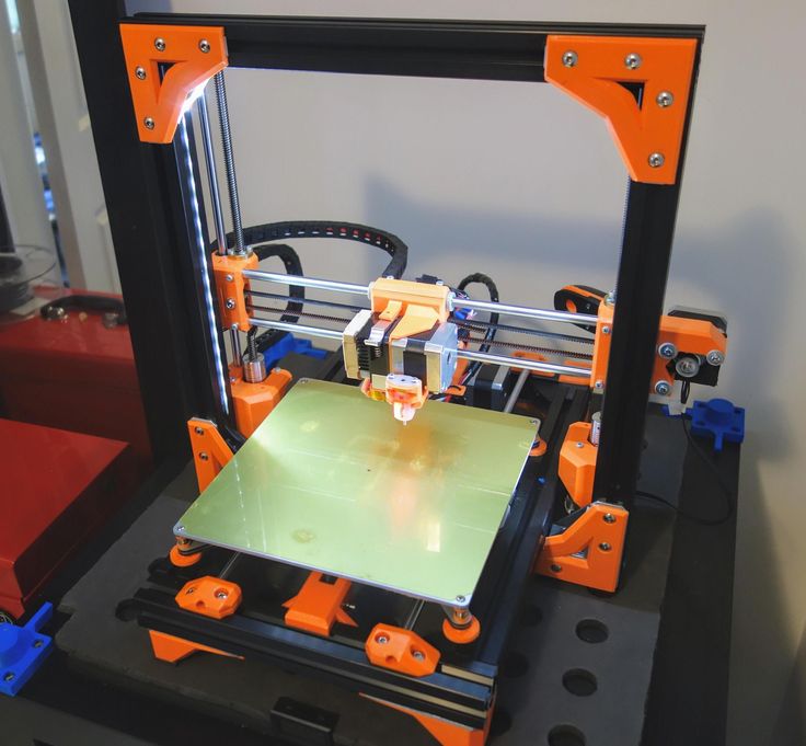 Someone sews a fur coat for a fabric printer, and someone is content with boxes.
But the goal, as always, is the same - to reduce the effect of drafts on the shrinkage of the part.
Key points for correct calibration of printers with this kinematics:
1) Place the printer on a level surface. Preferably horizontal. This requires a bubble level. Next, set the level of the position of the X axis.
2) Transfer to the home position. It is done either in the printer menu with the Home / Home command, if you are printing from a computer, then either with the G28 command in the command line, or with special buttons with the house icon.
Next, tighten the table screw so that the nozzle touches the glass. It did not press on the glass, but touched. We look at the light and twist. After that, move the extruder to another corner with the arrows in + X, + Y from the PC, or through menu
Turn the screw in the same way until it touches the nozzle.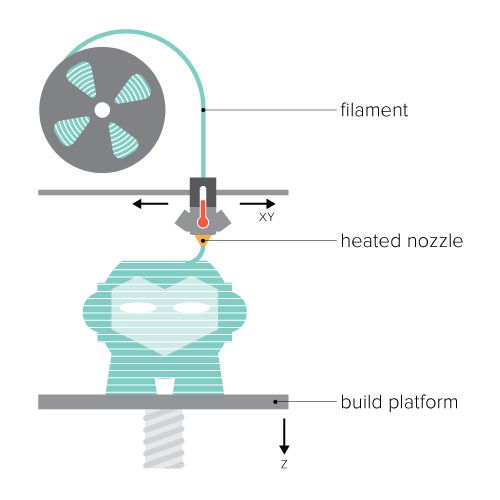 And repeat the operation for the remaining points.
I will try to save you from mistakes. In the photo of the printer above, the glass on the table is fastened with as many as 8 clamps. And it is quite possible that there will be a hump in the center. To avoid such problems, the glass should be fixed with 3 clamps. The plane is built, as is known from descriptive geometry, by 3 points. And calibration will be easier in this case. Just tighten the screw over the limit switch in Z.
For the nozzle to touch the glass in the middle of the side with 1 clamp. Then we distill the hot end into the corner where there is another clamp, tighten the table screw, and repeat the operation with another angle.
Regarding wobble.
All sorts of anti-wobble systems such as installing a bearing in the upper support do not work.
Just because putting 4 far from perfectly even cylinders in perfect parallel and in the same plane is an unrealistic task.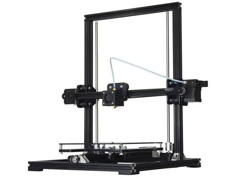 Especially on a flimsy acrylic frame with printed details. Therefore, if we take the straightness of the shafts as a constant, and set them parallel on the frame (purely hypothetically), and release the screws (from below the coupling for attaching to the motor) and nuts for attaching the X axis. Due to their curvature, the screws will spin like a mixer, but on printing will not be affected.
Otherwise, the design will work on who will be stronger in terms of bending resistance. And it will turn out far from a flat wall. Do you need it?
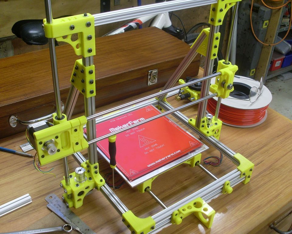
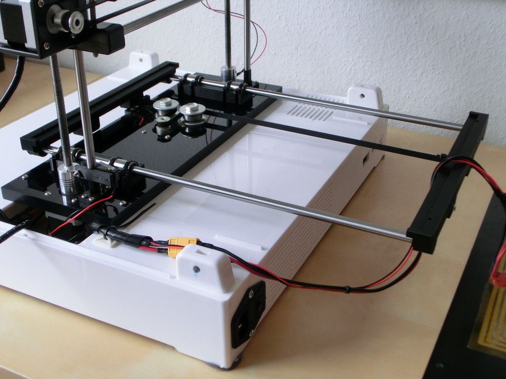
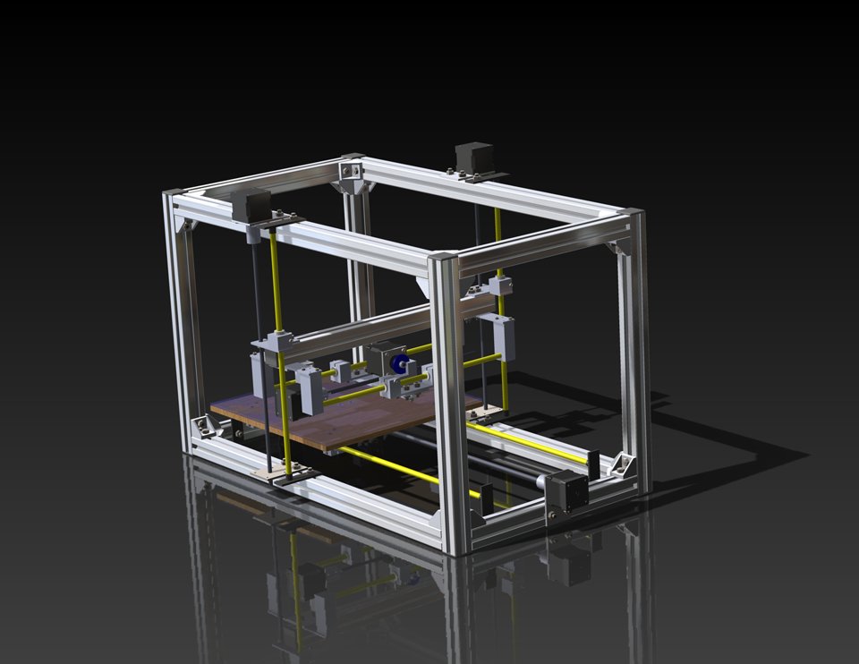
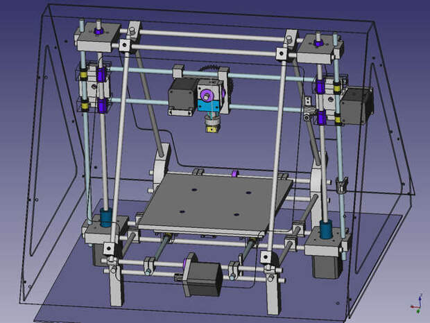
2. Kinematic design of Felix printers.
There are many such printers, such ones are made by MZTO (mz3d.ru), already mentioned by Felix. In fact, the kinematics are the same as those of the Prusa. axes independent of each other. Only now the table does not travel along one axis, but along two at once. Along the Z axis, and along the Y axis.
The design of the table is something like this.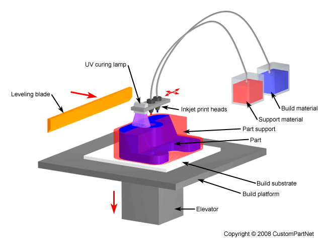
A platform rides on the Z shafts. The engine is on the back. The table moves along the rails with the help of a belt. The hotend moves only along one axis. The design is very funny, since the table weighs much more than the hotend, and they try to move it along 2 axes at once.
Advantages of this kinematics:
1) There is no second motor along the Z axis. There is no notorious wobble simply because there are 2 shafts and 1 propeller. The screw should also not be fixed from above. If it's not a ball screw.
Ball screw is a separate issue. If we take a high-quality ball screw, say, from the same Hiwin, then it is manufactured according to at least the 7th accuracy class (if rolled, and if polished, then the class is even higher) and must be installed in bearing supports. On the drive side, there are 2 back-to-back angular contact bearings, and on the other end, a radial with a loose fit to compensate for thermal expansion.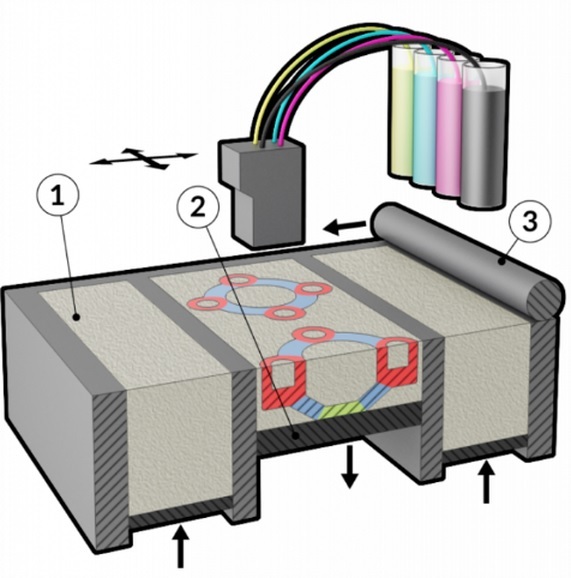
The purpose of mounting a ball screw is to ensure movement accuracy. If it is installed incorrectly, money is wasted, and the accuracy will not be higher than a screw-nut pair with a trapezoidal thread. For FDM, trapezoidal accuracy is more than enough.
2) Plenty of space for a direct extruder. As in the previous kinematics, there is room for creativity, to select the one and only extruder that you like.
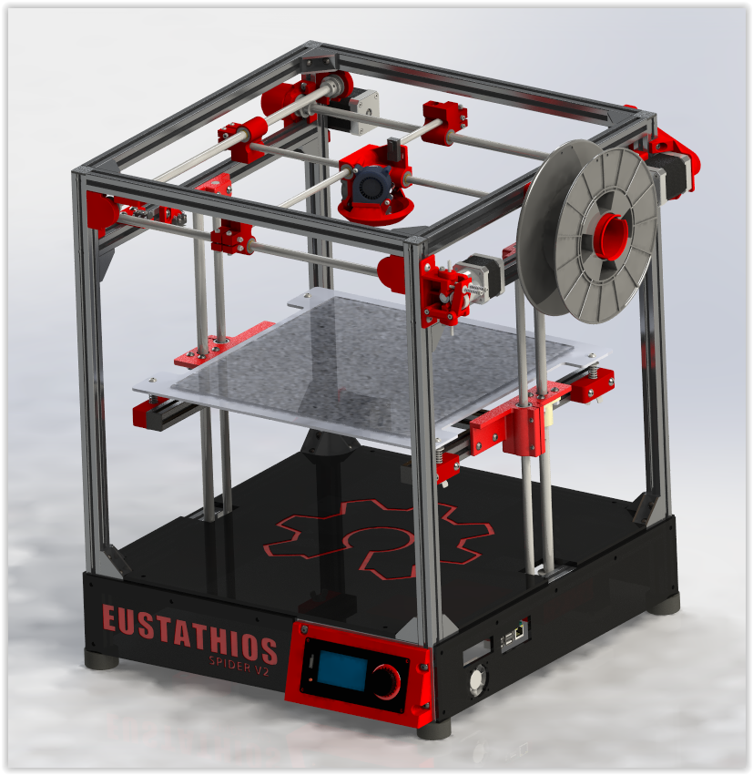
3) Rigid frame. It is possible to make a normal frame. Rigid, durable. Yes, even cast iron. The guys from Felix decided not to bother their heads and sculpt from an aluminum profile. MZTO went further, bent the steel sheet. And the shelf for the installation of the table was milled from a sheet of aluminum.
4) If we take the design of Felix on the profile, then by replacing a pair of pieces of the profile and the Z screw, you can increase the print area.
Just be sure to add stiffness.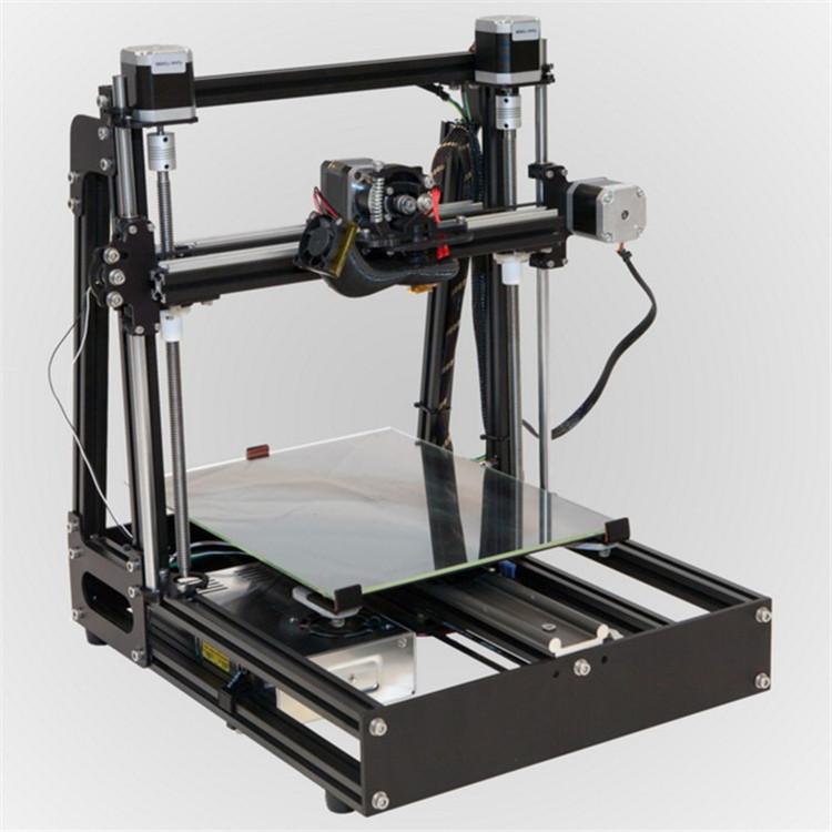 And it will turn out like a miracle of design thought. Big, meaningless and merciless.
Kinematic disadvantages:
1) Undoubtedly large twitching masses. The table back and forth, and if you turn on the movement along Z during idle movements (Z-hope), then there will be a disco.
2) There is no way to make him a normal heat chamber. The table moves back and forth and the temperature gradient simply blows away. Hence the problems when printing with nylons or ABS. Small drafts in the room will easily show you where the crayfish hibernate, how the material shrinks.
The calibration of the table of this printer is similar to the calibration of the Prusa table, only slightly simpler. It is easier due to the fact that you do not need to level the X-axis, it is automatically set when assembling the frame. We bring the nozzle to the table and twist the lambs.
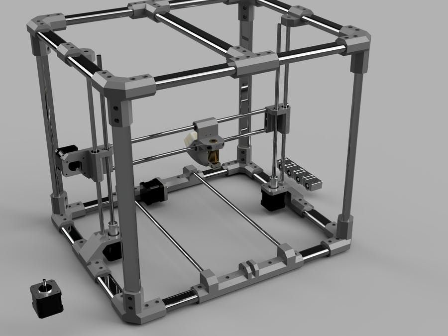
3. Ultimaker kinematics.
One of the most common variations of Cartesian kinematics.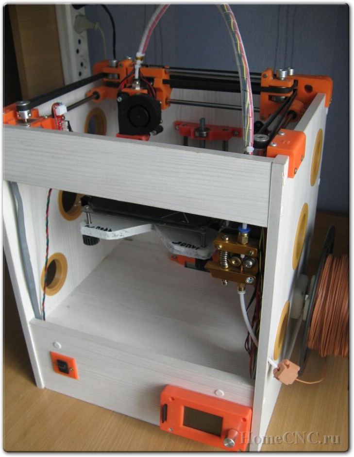
There are not very many such printers, but they do exist. Variation from Zortrax deserves attention. A variant of the same Raise is closer to the classics.
Zortrax has twin shafts, the reason is simple - they have a direct extruder with a full size Nema 17 motor. Raise Dual has a double direct extruder, so the classic 6 mm shafts are replaced by 8 mm. And the total weight of the 'head' is almost 900 grams.
Kinematics built entirely on shafts. They act both as guides and as pulleys. Kinematics also refers to Cartesian kinematics with independent movement along each axis by its own motor. Very picky about the straightness of the shafts. If you use curved shafts, you can get very funny artifacts on the walls of models. And they will be on all 3 coordinates. Most often it looks like a different thickness of the first layer and small waves along the walls. Therefore, all the salt and the high price of the original Ultimaker is only in high-quality components. Namely, in straight shafts. The belts are often used as ring belts, which simplifies their tensioning system, since it is important that all 4 belts are equally tensioned.
Advantages of this kinematics:
1) The table only moves along one axis. vertical. And the temperature gradient in no way suffers from this. The table is cantilever, so it is desirable to provide stiffeners or take this into account with the thickness of the table.
The metal fold on the table acts as a stiffener.
Many Chinese clones are equipped with such stiffening ribs for the table.
2) Despite the seeming complexity of the kinematic scheme, it is simple and each axis moves with its own motor.
3) The body is closed, which protects against drafts, and therefore delamination. Some put an acrylic door to heighten the effect.
Disadvantages of kinematics:
1) For good printing, it is not enough to buy a pack of even rollers.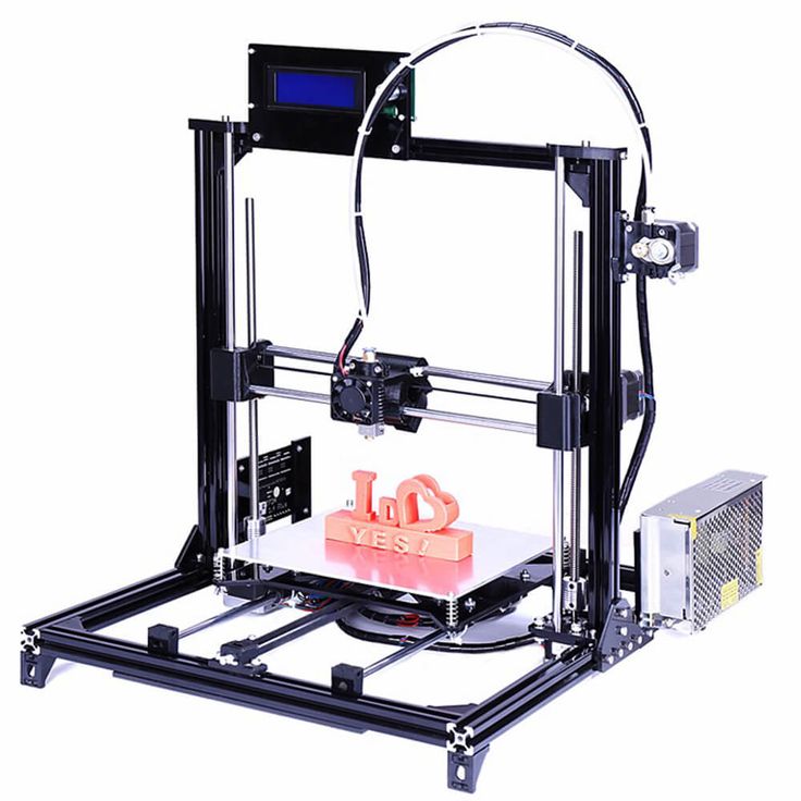 Collecting all these shafts correctly together is another task. At the same time and buy good bearings. Not that, Chinese junk, which is often sold on Ali, but normal bearings. If the bearings that are placed in the housing rotate poorly, the print will be jerky and with a shift in the layers. The consequences can be asked from Vanya (Plastmaska). Also, when buying leopard bushings, brass bearings with graphite inserts, be prepared for the fact that they will play. And if there is a backlash, the whole structure will knock.
And also, the Chinese like to push brass instead of bronze. And with even wear of brass and graphite, there will be an oily sticky black film on the shafts, which will make the movements harder. Ilya (tiger) offers good bushings. He also wrote about these difficulties.
2) All shaft parallels must be set correctly. I suggest using this device.
4 shafts that go along the walls of the body automatically stand up correctly, but it is important to set the crosspiece correctly in order to get angles 90 degrees in the XY plane.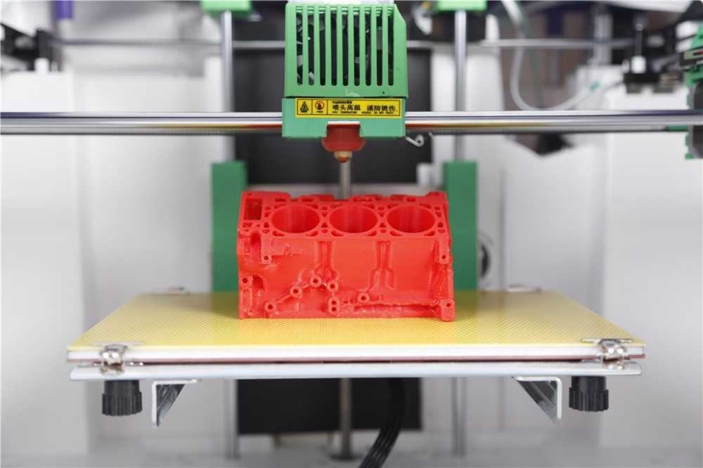
3) The design does not provide for an increase in the printable area with a couple of profile pieces, so the size of the hotend matters. Direct is difficult to put, but you can if you want.
Calibrating the table couldn't be easier. The table is often on 3 attachment points. Move the hot end by 3 points and turn the thumbs.
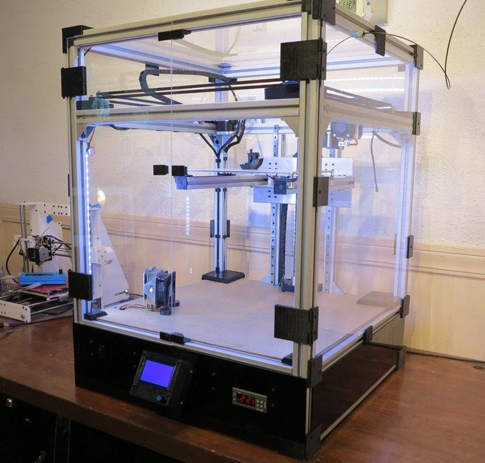
4. Kinematics used by Makerbot.
Also very widespread. In particular, printers from Makerbot, BQ, BCN3D, Magnum, magnum clone Zenit and quite tolerable makerbot replicas Flashforge and Hori work on this kinematic scheme.
In this case we have independent movement of each of the axes, with a Z table and all the resulting sides.
The main disadvantage is that the engine hangs on one side of the rolling beam, creating a kind of imbalance. This shortcoming was compensated in a two-extruder version - BCN3D Sigma. There, each bowden head has its own engine to move along the beam. And they are installed at the edges of the beam and balance each other.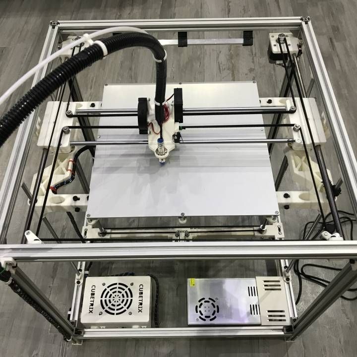 For uniform movement of each of the edges of the beam, 2 shafts, pulleys and belts are used. Belts must be tensioned equally.
Advantages of kinematics:
1) Independent movement of each axis.
2) Z-moving table. The temperature gradient does not suffer from 'blowing'.
3) Enclosed housing. If not closed, then there is a quite normal chance from the point of view of aesthetics to close it.
4) Scalable kinematics possible. Various BigREPs and others with 1m print areas use exactly this kinematics, as various H-bot/CoreXYs will ring like hell due to the presence of 4-5m belts and their stretching during accelerations.
Disadvantages of kinematics:
1) Unbalanced masses on the moving beam, hence the maximum print speed, with acceptable quality no more than 60-80 mm/s. Some manage to balance them and it is not so noticeable.
2) Bulky structures on the shafts to avoid imbalance during movements.
3) Make sure that the belt tensions on the right and left are the same.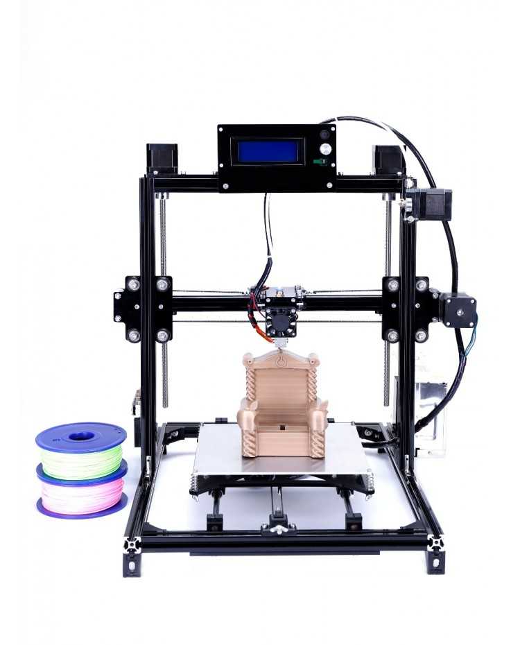
4. H-bot/CoreXY kinematics.
Next in distribution. Also Cartesian. Two motors are stationary, but move the carriage along the rails with one long piece of belt, or with two, but shorter. The math is more complicated than the previous ones, as it is necessary to synchronize the rotation of both motor rotors. That is, to move along each axis, you need to rotate both motors, and to move diagonally, only 1.
[IMG]http://www.doublejumpelectric.com/projects/core_xy/pics/hbot.svg[/IMG]
In fact, the mathematics for rotating motors is the same, but the implementation in mechanics is different. One of the biggest disadvantages of the H-bot over the CoreXY is that the belt tends to rotate the beam as it moves.
In the picture on the left, this is noticeable, the forces on the right and the forces on the left create a torque. Therefore, to implement this kinematics, the rigidity of the kinematic scheme is necessary. Most often it is implemented in rails.
With rigid beam. Some do, of course, on the shafts, but in the end - this is not a fountain.
And then they realize this and move to the rails.
For they are both easier to assemble and set up, and it is not necessary to invent carriages so that the shafts do not need to be fixed well.
CoreXY, unlike the H-bot, is driven by two belts.
And so, for ease of understanding, I will describe the positive and negative aspects of each variation of this kinematics.
H-bot.
Advantages:
1) Only one belt is needed, and the scheme provides for its operation without twisting.
2) It is more convenient to tension one belt than 2, so only one normal tensioner is needed in this scheme.
Even so.
Disadvantages:
1) The belt tends to stretch over time, and since the amount of stretching directly depends on the length, it is necessary to monitor its tension. Otherwise, you will get ugly waves on the surface before the stops.
With a loose belt tension, the carriage will have this play.
2) It is necessary to set the rollers strictly perpendicular to the XY plane, since if the roller is slightly skewed, the belt will be eaten against the roller shoulders. And we will get such a bullshit.
Tested in the skin and ZAV printer. Therefore, I always recommend that the rollers be fixed normally, and not cantilevered, in order to avoid bending the roller axis from belt tension.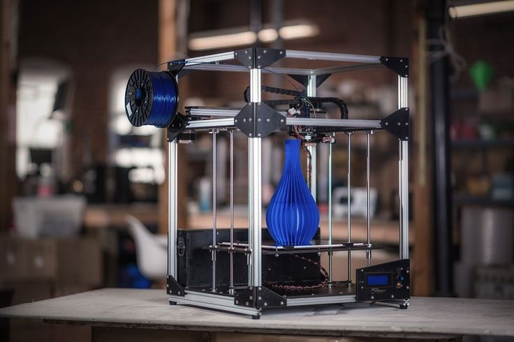
3) Complicated mathematics, due to which at speeds above 100 mm/s there may be problems with the lack of resources of 8 bit boards.
CoreXY.
Advantages:
1) Two short pieces of belt. They are easier to find than one long one.
2) The forces balance the beam, but do not tend to turn it, so these kinematics can also be assembled on shafts.
Disadvantages:
1) There are schemes with belt twisting and belt transition from one level to another - this is not very pleasant for a belt. Especially when one belt rubs against another. This moment is on video.
:{}
2) The difficulty of tightening the belts. They must be tensioned equally, otherwise the tension forces will tend to turn the carriage.
3) Complexity of assembly and development. It is necessary to maintain the verticality of the rollers, relative to the horizontality of the platform for installing motors and rails. A slight misalignment of the rollers will cause the belt to tend to slide down the roller, and if it rests against the shoulder of the roller, it will creak, if the shoulder is large, and if it is small, it will try to drive into it, as in the photo from the h-bot description .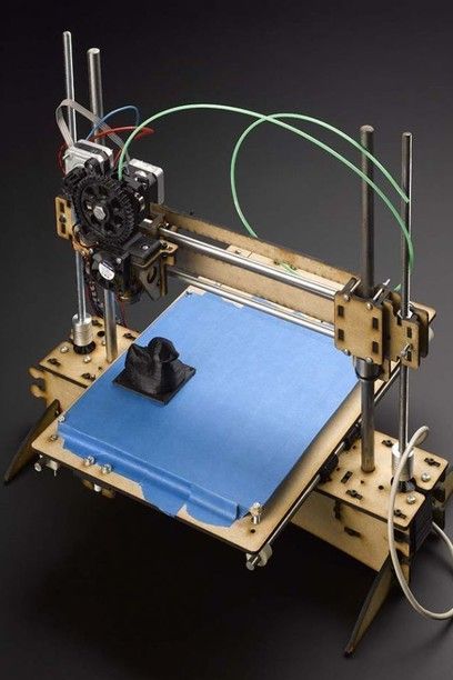
The general disadvantage of kinematics is poor scalability. That is, it is very problematic to set such a kinematics for a print area larger than 300 * 300 simply because of the elongation of the belt during printing. For small printers with high print speeds - one of the best kinematics.
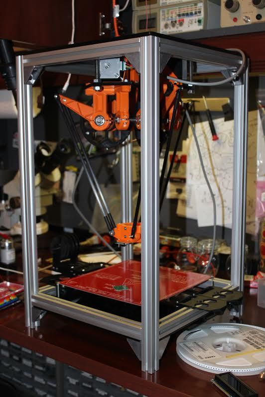
5. Delta kinematics.
The kinematics are based on the movements of the delta robot.
Only the hot end is installed instead of grippers. It has its own set-up problems, but it can take a very long time to print. It is rare when direct extruders are installed, since the effector (a platform for installing a hot end) is often mounted on magnets and it is necessary to unload it as much as possible. But in order to reduce the length of the tube (more specifically, the effect of the length of the tube on the print quality due to the correct adjustment of the retracts (pulling the plastic rod back to reduce its leakage from the expansion)) on the print quality, the extruder is hung on the same carriages, but on separate hangers.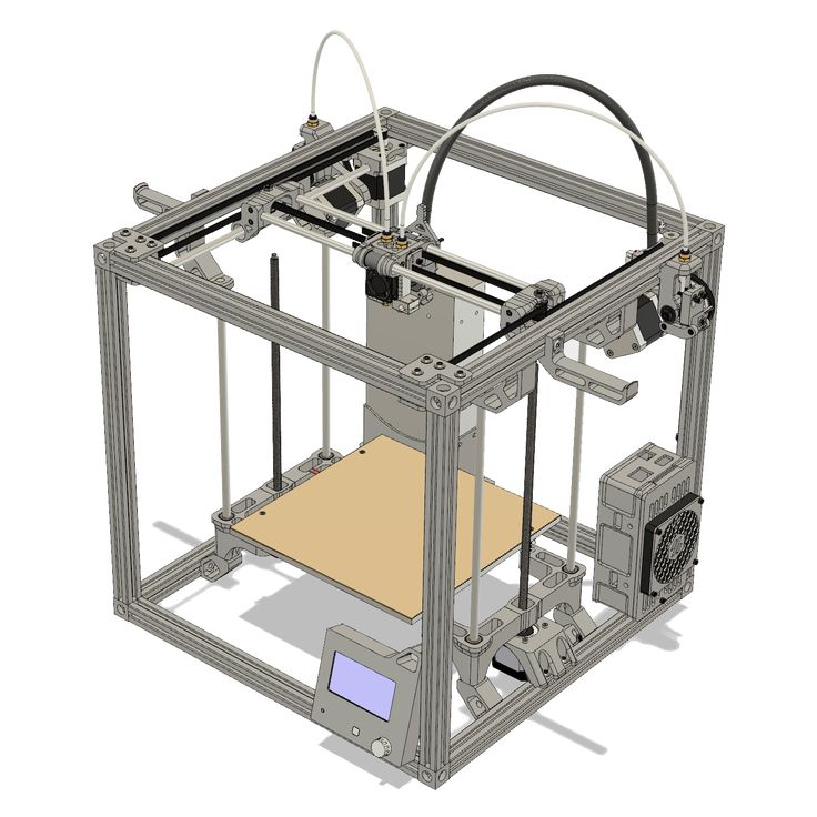 This reduces the length of the bowden tube and increases print quality.
Advantages:
1) Easy to customize. To increase the height, it is enough to buy 3 pieces of a longer profile, and increase the maximum height in the settings.
2) Takes up little space. It is more often high than bulky in length and width, due to this compactness.
3) If you make a light effector (carriage on which the hot end is installed), then you can achieve high speeds without losing print quality.
4) Vertical movement is the same as XY movement. Thus, there is no sticking of linear bearings on the table crossings, as in Cartesian printers, no extra motors rolling on the beam...
5) The absence of protrusions makes it possible to close the housing and stiffen the frame.
6) The aesthetic part - it's more interesting to stick to the work of the delta.
Disadvantages:
1) Difficult mathematics of movements, it is recommended to install 32-bit boards at once.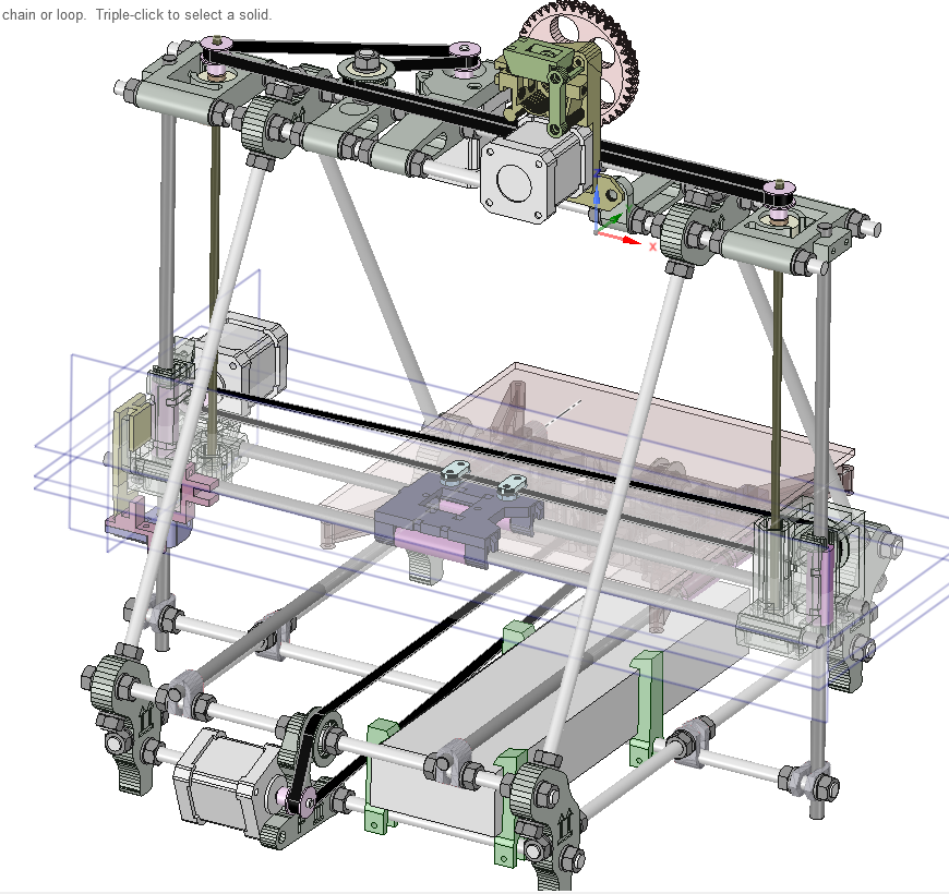
2) Complicated setting. A common problem in tuning is to remove the so-called 'lens', because each rod rotates with a radius, and if the tuning is incorrect, your printed plane will be either a convex or concave lens.
3) It is difficult and expensive to make a rigid frame, so that it would not dangle from the constant jerking of the carriages.
4) Difficulty installing a direct extruder. It turns out to be heavy, and since many deltas are made on magnets, it will not be possible to accelerate. Although, there is one neat and easy solution - installing a ready-made direct extruder with a gearbox. Like E3D Titan Aero or Bondtech BMG.
5) Parts precision problems - any unevenness and misalignment will be visible even if they are on the same axis. And they add up along the axes.
To sum up , do you want a small printer (not larger than 300*300 mm) with nimble kinematics? Then you should go to Ultimaker or H-bot/CoreXY.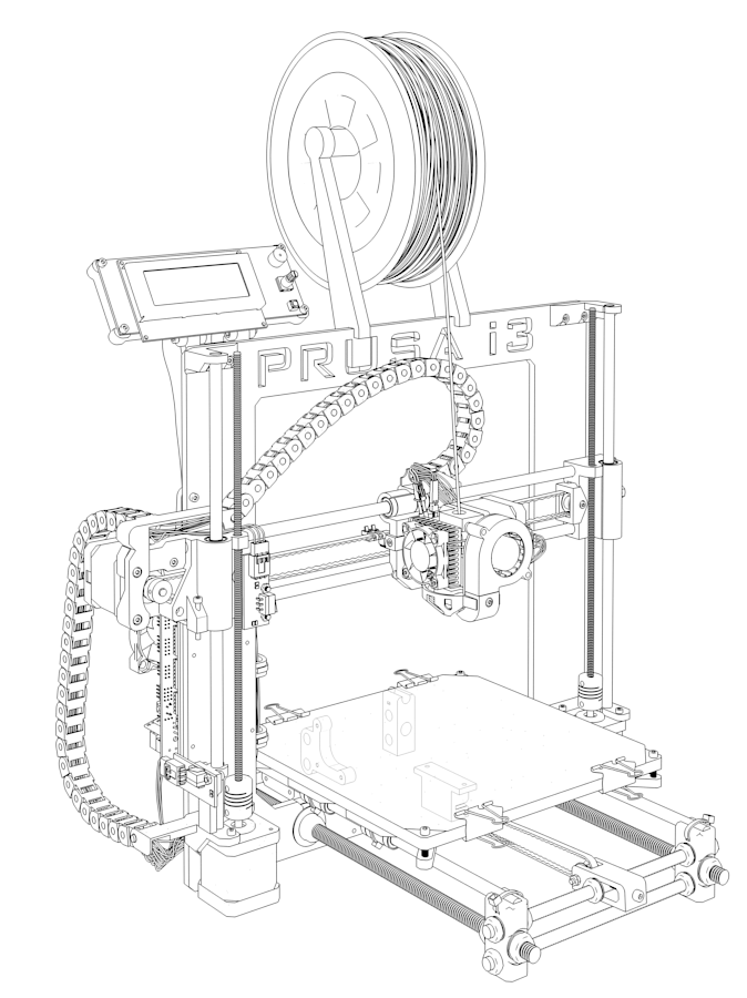 Need a printer with a large printable area or 2 independent extruders? Then to Makerbot. If you print vases, hookahs and sufficiently high details - delta. For everything else there is a classic - Prusa. Experiments with double carriages, chocolate, engravings? Yes, anything. And most importantly - cheap.
You can even screw on 4 colors.
Kinematics of 3D printers: what are the best types
Kinematics of 3D printers - which device to choose?
The print quality of a 3D printer and how it works depends on several factors. One of the important indicators is kinematics. This article discusses its main types and their features.
- What is the kinematics of 3D printers?
- Types and types of kinematics
What is the kinematics of 3D printers?
Each 3D printer has its own kinematics.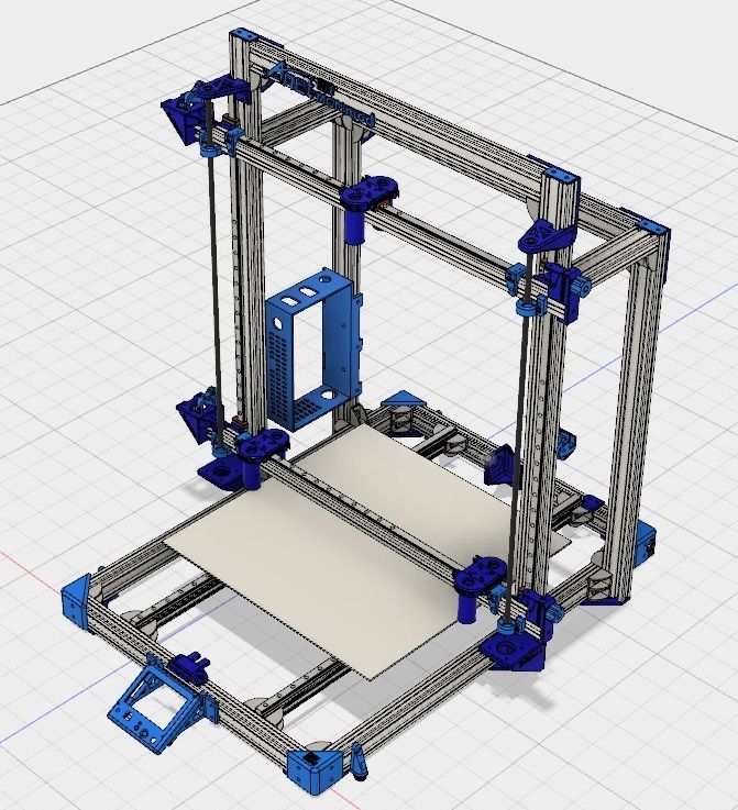 Models are equipped with a platform and an extruder. These parts move in a certain direction relative to each other. Kinematics in such a device means the scheme along which the extruder and platform move.
Types and types
There are five types of 3D printer kinematics. The principle of operation of the device and the method of processing the workpiece depend on their features.
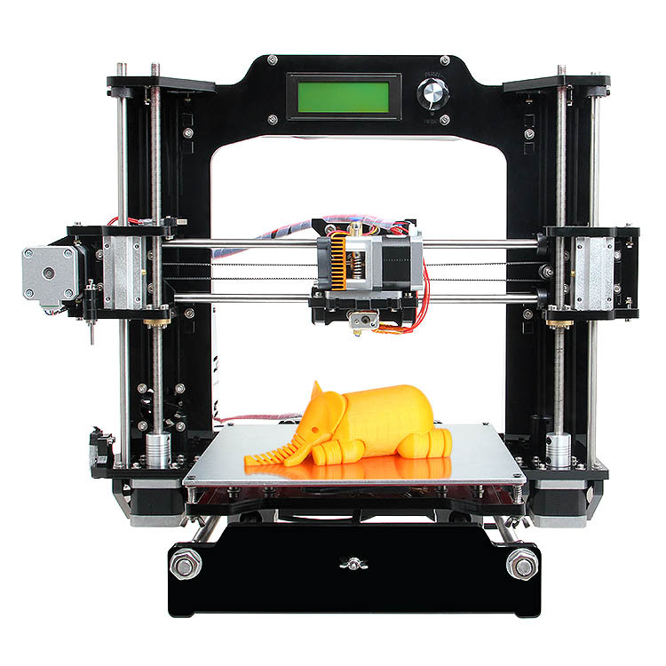
Cartesian 3D printers
The most common are 3D printers with Cartesian kinematics. They are based on the Cartesian coordinate system, they work in the X, Y and Z axes. They set the coordinates by which the print head changes position relative to the platform. The printhead has limitations in terms of movement in three axes.
- The extruder moves up when the platform moves in the horizontal X or Y axis.
- The platform moves up in the Z axis, the extruder can move in the horizontal directions at this moment.
- The platform moves along one of the axes in height, the extruder rises along the other axis.
- The platform is static and does not move, the extruder moves in all three axes.
- The extruder moves along the coordinates in height, and the platform moves along the X and Y axes.
The most common options during operation are the first and second.
Cartesian kinematics has a number of advantages.
- This is a simple motion pattern suitable for hobby printing. Many budget models work on its basis.
- The printer can be produced in any dimensions, if necessary, it is upgraded.
- Consumables are freely available. Users are offered a large number of materials and colors.
- The printers can be shipped unassembled. This feature allows beginners in the world of 3D printing to understand the principle of the mechanism.
- Devices based on the Cartesian system, suitable for mass production of parts. They are designed to create blanks of different sizes.
Among the shortcomings of printers built on the principle of three coordinate systems, there are two factors:
- models are bulky, after assembly they take up a lot of space on the desktop;
- The print speed is slow.
Cartesian kinematic printers suitable for hobby printing. They help beginners understand the process of work and learn how to create models.
Example of printing on a device with Cartesian kinematics.
Varieties of Cartesian kinematics CoreXY and H-Bot
The CoreXY has two feed belts, while the H-Bot has only one, but it is long - this is the main difference between the two varieties. The common feature in these devices based on Cartesian kinematics is that the platform moves only along the Z axis. The horizontal X and Y axes are moved by a pair of motors mounted on the frame.
Two motors are responsible for movement along the horizontal axes, one motor along the vertical axes. Such kinematics is common not only in amateur printers, but also in professional ones.
CoreXY and H-Bot based 3D printers are more expensive than conventional Cartesian models. For the production of their cases, a metal alloy or composite materials are used. Rail guides unleash the potential of high-quality printing. This kinematics allows you to achieve good detail with fast printing.
The advantages of CoreXY and H-Bot are:
- high print speed;
- quality detailing of models;
- professional grade use.
But not without drawbacks:
- H-Bot is not implemented on steel shafts;
- it is necessary to constantly monitor the tension of the belt so that there is no play;
- high cost of instruments;
- belts can wear out quickly if they rub against neighboring objects during operation, this factor must be taken into account during operation;
- the pulleys on which the belts move must be located strictly perpendicular to each other.
Cartesian kinematic printers are widely used in various industries. They are distinguished by high print detail, a durable metal case, and high-quality components.
Help! Cartesian kinematics allows you to create detailed objects at high speed.
Delta Printers
Delta kinematic printers differ from their competitors in a number of ways. The table remains stationary, and three fixed axes are used to move the print head at once. In such devices, there is no division into the X, Y and Z axis. To move the carriage sideways, you need to lower one axis, and raise the rest.
Help! In the production of 3D printers, the Delta kinematics has not yet found wide distribution. This is a promising direction, which is currently being developed by developers.
Already existing delta printers offer the following advantages.
- Small dimensions. Devices do not take up much space on the desktop, they are tall, but not wide.
- High print speed. Models can process 300–400 mm/s.
- A new approach to blank making. The equipment does not print using the same technology as Cartesian. It is interesting to watch the process of processing the model.

Deltas also have a few drawbacks.
- Calibration complexity. A lens is formed on the printed surface, due to which it is impossible to fully calibrate the printing process. This is the main factor slowing down the mass introduction of kinematics.
- Poor accuracy. High print speeds sacrifice accuracy. All axes perform small movements, errors occur.
- Computing power requirements. Deltas are equipped with 32-bit boards, which is why they do not support interaction with 8-bit systems.
- The frame must be rigid. This is necessary to avoid backlash, deviations and distortions.
- Not all extruders will fit. Deltas have weight restrictions, so direct type extruders are not allowed.
Printing accuracy remains high.
On deltas, you can build high-quality vertical models, even with large dimensions. There are no protruding parts on the body, which allows you to independently increase its rigidity.
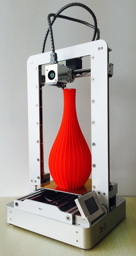
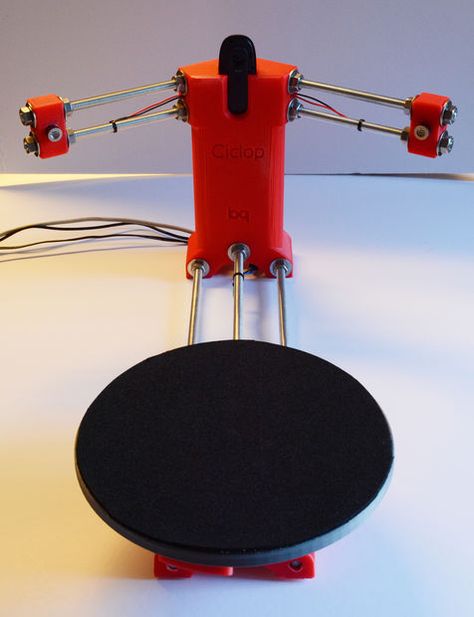
Polar
The polar kinematic scheme is represented by only one company - Polar. The essence of this technology lies in the fact that it does not have positioning along the X, Y and Z axes. The position of the extruder is set by the angle and radius. The platform of polar 3D printers is round in shape, it moves only along the horizontal axis and only rotates in a circle. The extruder moves up and down.
The advantages of 3D printers based on polar kinematics are:
- the ability to create large objects;
- high energy efficiency;
- material savings;
- small dimensions.
But there are also disadvantages:
- low print accuracy, which was started by Polar representatives;
- platform does not warm up during operation;
- material restrictions - ABS plastic cannot be processed.
Polar printers are less accurate than Cartesian and Delta printers. The manufacturer recommends using such models for educational purposes; they are not yet suitable for professional printing.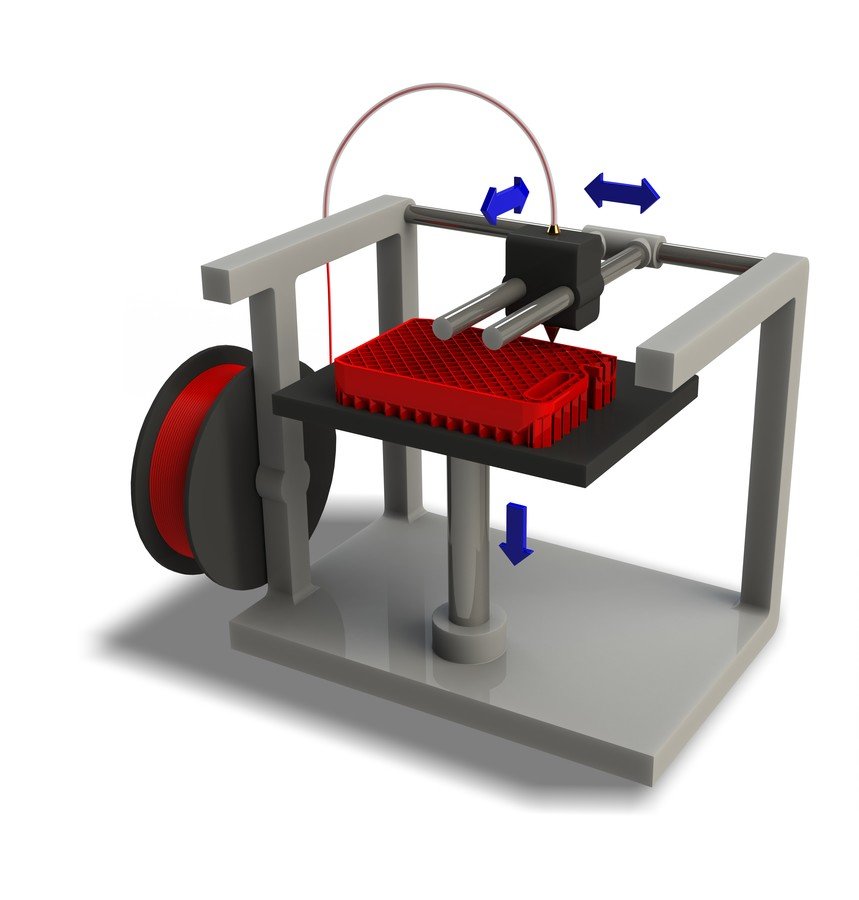
Printing example shows that accuracy cannot be achieved. All features are blurred, the figure lacks sharpness and clarity.
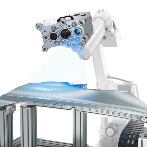
With robotic arms
Printers with robotic arms are a design with a mechanically programmable extruder gripper arm. This is a multifunctional robot: it can carry out welding, painting, milling, etc.
The extruder can move in different directions: in layers, along complex paths in three dimensions, at different angles. Thanks to this set of functions, it is possible to create complex designs.
The main advantages are:
- versatility: the device can perform several types of tasks when replacing the extruder;
- are suitable for industrial applications: you can print large objects with almost no size restrictions.
But there are also disadvantages:
- low accuracy: such equipment is inferior to Cartesian kinematics;
- large size: devices take up a lot of work surface space.

These models are not suitable for professional 3D printing. They can be considered as an object for a hobby or a tool for it. For industrial purposes, such devices work only when high precision in the execution of parts is unimportant.
SCARA
SCARA (Selective Compliance Articulated Robot Arm) is a kinematics based on horizontal rotation of the platform. The movement is achieved by the articulation of the linkage mechanism.
These instruments are highly accurate and repeatable, and operate with a minimum of noise and vibration. SCARA also surpassed the Cartesian models in terms of processing detail: the difference is that the former work noticeably faster.
Advantages of such kinematics:
- print accuracy;
- high workpiece processing speed;
- small dimensions and weight.
But there are also disadvantages:
- stiffness restrictions in the area of the X and Y axes;
- high cost;
- is not the widest area of use.
SCARA kinematic devices are devices that combine the functions of a 3D printer and a manipulator. Device actions are programmed through software or an installed mobile application.
The choice of kinematics for 3D printers depends on the requirements for technology and application.
- Cartesian kinematic models remain the most common. They combine high accuracy, good speed, small dimensions. They can be used for amateur 3D printing. They work in a Cartesian coordinate system, the platform and the extruder move along the X, Y, Z axes.
- CoreXY and H-Bot are varieties of Cartesian kinematics. They are highly detailed blanks, suitable for professional use. Their disadvantage is the complexity in the process of operation. The user must constantly ensure that the belts do not come into contact with foreign objects and are well tensioned.
- Delta printers are uncommon models whose weak point is print accuracy. In the process of working with the device, there are problems with calibration, as well as with the choice of extruder.