3D printer parameters
Optimization of 3D Printing Process Parameters of Polylactic Acid Filament Based on the Mechanical Test
On this page
AbstractIntroductionMethods and MaterialsResultsConclusionData AvailabilityConflicts of InterestAcknowledgmentsReferencesCopyrightRelated Articles
The main objective of this research study is to optimize the printing parameters that can be used in the FDM (fusion deposition modeling) production method to obtain the lowest production time and best printing parameter of PLA (polylactic acid) filament with the tensile test. The printing parameter that can be used in FDM machines such as extruder temperature, bed temperature, layer height, printing speed, travel speed, infill, and shell count is taken into account for optimization. In addition, the tensile specimens from ASTM (American Society for Testing and Materials) D638 standard were manufactured by PLA filament with the above-modified printing parameters. The best printing parameters for PLA products were found by the time recorded during production and tensile test results after production. Thus, through this research, one can find the best PLA filament printing parameters and their timing.
1. Introduction
Additive manufacturing (AM) attracts attention in various fields of manufacturing sectors for producing slightly more difficult geometrical designs products. Moreover, AM has been considered by researchers in recent decades and can be future manufacturing technology instead of the CM (conventional manufacturing) method and digital data alone are considered sufficient in AM to produce an object. Digital data are converted to STL (standard triangle language) and sliced by slicing software and fed as input to a 3D printer machine, and the 3D printer generates the given input data layer-by-layer as the final product. It can easily produce the final products with less wastage and in a very short time [1–3].
Earlier researchers described AM-based types, characteristics, policies, presence, and potential in the market in [4–9]. Some studies show that manufacturers focus only on production costs and time. Various tactics are employed for this. The PLA filament that can be used in FDM machine attracts the attention of the manufacturers due to its low cost and high availability.
Therefore, this research study aims to determine the best printing parameters of PLA filament based on production time and tensile test (mechanical property). A large number of previous researchers have experimented with 3D-printed material. Fragassa et al. [10] explored the properties of four photopolymer resins. This research ensured the physical characteristics and nominal mechanical properties of tensile and bending strength. However, the authors of this study recommend personal evaluation when considering other characteristics.
According to Talic et al. [11], ABS (acrylonitrile–butadiene–styrene) and PLA filament are considered the most popular filament in the field. PLA filament has slightly higher strength and stiffness compared to ABS filament. PLA filament is also considered to be slightly easier to print and PLA filament as a good alternative to ABS filament in a material extrusion method. It has been considered by previous researchers [12–14].
Today, PLA filament is utilised in a variety of applications, and its availability in the market is substantial. Sugarcane and maize starch are the two primary components used in the production of PLA filament, a type of biodegradable thermoplastic. Therefore, neither the consumers nor the environment are harmed by it in any way [15–17].
Polyether-ether-ketone (PEEK) has been considered by earlier researchers as an alternative to PLA filament and ABS filament [18]. But this is not immediately useable on the 3D printing machine.
Finally, Galeta et al. [19] explored the tensile strength influence of processing factor in the 3D printing model on their research.
2. Methods and Materials
In this test, the minimum production time is first calculated by modifying several printing parameters of the FDM machine that can be used in AM and creating tensile specimens for the same ASTM D638.
This research study calculates the breaking point, true strain at maximum load, and true strain at break percentage of the five tensile specimens produced. For this, the previously mentioned printing parameters such as extruder temperature, bed temperature, layer height, print speed, travel speed, and shell count are taken into account. Flash forge for slicing software and Botzlab Wanhao Duplicator 4S were used as the manufacturing machine.
The procedure for producing ASTM D638 tensile specimens is as follows:(1)Designing model by solid works SP2.0(2)Converting solid works the SP 2.0 model in to STL file (a standard format for 3D printers)(3)During the .STL conversion, the printing parameters given in Table 1 are taken into account by change common for all 5 tensile specimens(4)Creating a 3D physical model by the FDM machine(5)The making time of each specimen is given in Table 1 (ensure the slicing software time and actual time).
2.1. Printing Parameters in Additive Manufacturing
The printing parameters are commonly considered in 3D printing by previous researchers, as given in Table 1. The extruder temperature was found to be above 200°C as the melting point of the PLA filament by previous researchers [15–19].
The extruder temperature used in this research study is a minimum of 200°C and a maximum of 219°C. The bed temperature used is a minimum of 0°C and a maximum of 50°C. An initial layer height of 0.12 mm to a maximum of 0.23 mm was used during production. Printing speeds ranging from a minimum of 30 mm/s to a maximum of 75 mm/s are used. Extruder travel speeds range from a minimum of 60 mm/s to a maximum of 90 mm/s.
Infill (pattern/density (%)) is considered as the most important printing parameter in 3D printing in optimization. Hexagonal pattern (15%) for specimen I, line pattern (15%) for specimen II, triangle 35° pattern (30%) for specimen III, 3D infill pattern (20%) for specimen IV, and triangle 55° pattern (35%) for specimen V as infill in this research study have been used.
Finally, the shell count is used as a minimum of 2 and a maximum of 3 in the optimization parameter.
2.2. Tensile Specimens ASTM D638
The design was first selected for ASTM [20] standards D638 type 5 polymers that can be used to determine the mechanical properties of the selected PLA material, and this is shown in Figure 1.
Figure 2 shows 5 tensile specimens generated by different printing parameters. The Boltzlab Wanhao Duplicator 4S, the most popular FDM machine on the market, has been used in this research to produce these tensile specimens, and this is shown in Figure 3.
3. Tensile Test
An Instron 5980 series tensile testing machine was used at 5 mm/min. The tensile testing machine setup is shown in Figure 4, and Figure 5 shows the failure of the tensile specimen.
3.1. Braking Point
Table 2 provides the braking points of the specimens. The minimum specimen II is 0.24185 and the maximum specimen III is 0.98919 braking.
3.2. True Strain at Maximum Load
The minimum specimen IV is calculated to be 0.08958 and the maximum specimen I is calculated to be 0.10823. This is given in Table 3.
3.3. Tensile Strain Brake Percentage
The maximum tensile strain percentage is calculated as specimen III and the minimum tensile percentage is calculated as specimen V and is given in Table 4. The load-extension diagrams of each tensile specimen are shown in Figures 6–10.
3.4. Load-Extension Diagrams
The tensile load-extension curve of specimen 1 is shown in Figure 6. Figure 6 shows that specimen I can withstand weighs up to 750 N and shows the extension up to 13.56%.
The tensile load-extension curve of specimen II is shown in Figure 7. Figure 7 shows that specimen II can withstand weighs up to 650 N, and it shows an extension up to 10.909%.
The tensile load-extension curve of specimen III is shown in Figure 8. It shows that specimen III can withstand weighs up to 650 N and shows the extension up to 13.850%
The tensile load-extension curve of specimen IV is shown in Figure 9. It shows that specimen IV can withstand weighs up to 550 N and shows the extension up to 10.974%.
The tensile load-extension curve of specimen V is shown in Figure 10. It shows that specimen V can withstand weighs up to 650 N and shows the extension up to 10.311%.
4.
 Results
This experimental investigation describes the best printing parameters of PLA filament. Table 1 provides the printing parameters and the time it took to produce the specimen. Specimen IV has the shortest time (8 minutes), and next, the specimen V can be produced in 9 minutes. Then, specimen III takes 10 minutes. Specimen I produced in 12 minutes and specimen II in 18 minutes.
Figure 11 shows the printing time of each specimen and specimen II except all the specimens as below the average time. The average time is calculated for conclude normal or least time of making anything, and this practice is also followed in manufacturing sectors. The average time is calculated by the following equation.
The load extrusion diagram also describes the maximum weight of the specimen. From this, specimen I withstands weighs 750 N, and the specimen II, III, and V withstand weighs 650 N and the specimen IV withstand 550 N. Figure 12 shows the tensile strength of each specimen.
According to specimen III, tensile strain percentage withstands high extrusion based on 13.850%. Also, specimen I withstands the extrusion to 13.573%, specimen IV to 10.974%, specimen II to 10.979%, and specimen V to 10.311%.
The main purpose of this research is to select an optimal slicing/printing parameter according to the short time and tensile properties. It basically considers less time specimens such as specimens IV, specimen V, specimen III, and specimen I.
Then, on the basis of the tensile test of these four specimens, the specimen I withstands 13.573% longer extension and withstands the weighs 750 N than specimen III, specimen IV, and specimen V.
Therefore, the printing parameters of specimen I are selected as the best one for the PLA filament. Thus, the extruder temperature is 200°C, the bed temperature is 50°C the layer height is 0.18 mm, the printing speed is 60 mm/s, and the travel speed is 80 mm/s. The most important printing parameter is infill pattern hexagonal and infill density 15%, and the shell count is chosen to be 2.
5. Conclusion
Nowadays, manufacturers are trying to produce more finished products in less time. There are many tactics used to do this. This research study aims to determine the best printing parameter for PLA filament based on time and tensile test. For this purpose, 5 ASTM D638 tensile specimens were manufactured with PLA filament with the help of the modern 3D printer, and the tensile test was performed on it. On basis of time, specimen IV, specimen V, specimen III, and specimen I are less than specimen II.
Only the production time of the specimen was taken into account in this research study. This is because the time to change is often determined when slicing the model produced by the slicing software. Thus, the time available after slicing the model by the slicing software is sometimes subject to change.
Then, based on the tensile test, compared to specimen IV, specimen III, and specimen V, specimen I withstands more weight and moderate extension. So, the printing parameter of specimen I is said to be the best printing parameter at the end of this research.
The continuation of this research is to produce homogeneous specimens that are identical to the printing parameters of future selected specimens and to analyze microstructures based on temperature.
Data Availability
The data used to support the findings of this study are available from the corresponding author upon request.
Conflicts of Interest
The authors declare that they have no conflicts of interest.
Acknowledgments
The authors thank Dr. G. Viswanathan, founder, VIT University, for the constant encouragement and motivation in publishing this article and the lab in-charges and technical assistants of additive manufacturing laboratories and tensile testing, VIT Vellore, for the facility provided to carry out this research work.
References
L. F. C. S. Durão, R. Barkoczy, E. Zancul, L. Lee Ho, and R. Bonnard, “Optimizing additive manufacturing parameters for the fused deposition modeling technology using a design of experiments,” Progress in Additive Manufacturing, vol.
 4, no. 3, pp. 291–313, 2019.
View at:
Publisher Site | Google Scholar
L. Berrocal, R. Fernández, S. González et al., “Topology optimization and additive manufacturing for aerospace components,” Progress in Additive Manufacturing, vol. 4, no. 2, pp. 83–95, 2019.
View at:
Publisher Site | Google Scholar
J. M. Hamel, C. Salsbury, and A. Bouck, “Characterizing the effects of additive manufacturing process settings on part performance using approximation-assisted multi-objective optimization,” Progress in Additive Manufacturing, vol. 3, no. 3, pp. 123–143, 2018.
View at:
Publisher Site | Google Scholar
ASTM International Designation, Standard Terminology for Additive Manufacturing Technologies, ASTM International Designation, West Conshohocken, PA, USA, 2012.
Wohlers Report 2021, 3D Printing and Additive Manufacturing, State of the Industry, Annual Worldwide Progress Report, Wohlers Associates, Fort Collins, CO USA, 2021.
I. Gibson, D. W. Rosen, and B. Stucker, Additive Manufacturing Technologies, Springer Science, Berlin, Germany, 2015.
E. Grenda, Printing the Future, the 3D Printing and Rapid Prototyping Source Book, Castle Island Company, Arlington, TX USA, 3rd edition, 2005.
Y. K. S. S. Rao, C. S. Dhanalakshmi, D. K. Vairavel et al., “Investigation on forestry wood wastes: pyrolysis and thermal characteristics of Ficus religiosa for energy recovery system,” Advances in Materials Science and Engineering, vol. 2022, Article ID 3314606, 9 pages, 2022.
View at:
Publisher Site | Google Scholar
N. Grujović, J. Borota, M. Šljivić, D. Divac, and V. Rankovi, “Art and design optimized 3D printing,” in Proceedings of the 34th International Conference on Production Engineering, Niš, Serbia, 2011.
View at:
Google Scholar
C. Fragassa, G. Minak, and E. Poodts, Mechanical characterization of photopolymer resins for raid prototyping, paper presented at the 27th Danubia- Adria Symposium on Advances in Experimental Mechanics, 2010.
A. Talić, A. Durmić, M. Šljivić, and M. Stanojević, “The process of developing conceptual design of a product using rapid prototyping technology,” in Proceedings of the 18th International Research/Expert Conference TMT, Budapest, Hungary, 2014.
View at:
Google Scholar
S. Ahn, M. Montero, D. Odell, S. Roundy, and P. K. Wright, “Anisotropic material properties of fused deposition modeling ABS,” Rapid Prototyping Journal, vol. 8, no. 4, pp. 248–257, 2002.
View at:
Publisher Site | Google Scholar
I.
 Gibson, D. W. Rosen, and B. Stucker, Additive Manufacturing Technologies (Rapid Prototyping and Direct Digital Manufacturing), Springer Science, Berlin, Germany, 2010.
F. W. Liou, “Rapid prototyping and engineering applications (A toolbox for prototype development),” Rapid Prototyping Processes: Liquid-Based, Solid Based, Powder Based, CRC Press, Boca Raton, FL, USA, 2008.
View at:
Google Scholar
R. Rangaraj, S. Sathish, T. L. D. Mansadevi et al., “Investigation of weight fraction and alkaline treatment on catechu linnaeus/Hibiscus cannabinus/sansevieria ehrenbergii plant fibers-reinforced epoxy hybrid composites,” Advances in Materials Science and Engineering, vol. 2022, Article ID 4940531, 9 pages, 2022.
View at:
Publisher Site | Google Scholar
D. M. Bigg, “Mechanical properties of particulate filled polymers,” Polymer Composites, vol.
 8, no. 2, pp. 115–122, 1987.
View at:
Publisher Site | Google Scholar
B. Rašuo, Aircraft Production Technology, Faculty of Mechanical Engineering, University of Belgrade, Belgrade, Serbia, 1995.
W. Wu, P. Geng, G. Li, D. Zhao, H. Zhang, and J. Zhao, “Influence of layer thickness and raster angle on the mechanical properties of 3D-printed PEEK and a comparative mechanical study between PEEK and ABS,” Materials, vol. 8, no. 9, pp. 5834–5846, 2015.
View at:
Publisher Site | Google Scholar
T. Galeta, I. Kladaric, and M. Karakas, “Influence of processing factors on the tensile strength of 3Dprinted models,” MTAEC9, vol. 47, no. 6, p. 781, 2013.
View at:
Google Scholar
K. C. Sekhar, R. Surakasi, D.
 P. Roy et al., “Mechanical behavior of aluminum and graphene nanopowder-based composites,” International Journal of Chemical Engineering, vol. 2022, Article ID 2224482, pp. 1–13, 2022.
View at:
Publisher Site | Google Scholar
Copyright
Copyright © 2022 S. Raja et al. This is an open access article distributed under the Creative Commons Attribution License, which permits unrestricted use, distribution, and reproduction in any medium, provided the original work is properly cited.
What are the optimal shell and infill parameters for FDM 3D printing?
How do shell and infill properties impact the performance and cost of FDM 3D printing? It turns out these parameters have more of an effect than you may realize, so learning to optimize these features will improve the performance of your FDM custom parts while reducing manufacturing costs.
The majority of FDM 3D-printed parts are not printed solid. Printing solid parts requires high amounts of material and longer print times, resulting in high costs. To optimize the printing process most parts are printed with solid shells and filled with infill. Shells and infill play an important role on the quality, appearance and function of FDM printed parts.
This article will discuss the difference between shells and infill and how shells and infill can be employed to optimize a design. To level up your design skills for 3D printing, check out this comprehensive one-pager with all of Hubs' top design rules .
What are the major components of an FDM 3D print?
A standard FDM print can be broken down into 4 sections: shells, bottom layers, top layers and infill.
-
Shells: The walls of the print that are exposed to the outside of the model
-
Bottom layers (a type of shell): The part of the print that is exposed to the outside of the model, facing the build plate
-
Top layers (a type of shell): The parts of the print that is exposed to the outside of the model, facing upwards, towards the nozzle.
 Typically this surface will have the best surface finish
 -
Infill: The internal structure of the print
The parameters of these sections can each be altered to optimize a design.
These are the four sections of an FDM print that designers can alter if need be.What are shells in FDM 3D printing?
Shells are the number of layers on the outside of a print. For FDM printing, shells are always the first areas to be printed per layer. Let’s unpack several key design considerations for optimizing shells.
-
Strength can be added by increasing the shell thickness. This allows for a slightly more robust print without having to increase the amount of material used for infill. Most slicer programs allow shell thickness to be adjusted even allowing areas of high stress to be customized with a high shell density offering localized areas of high strength.
-
If you plan on finishing a print by using sanding or chemical smoothing, increasing shell thickness is often necessary. This is because post-processing methods reduce the thickness of the surface of the model.
-
Any increase in the number of shells also increases the amount of time and material required to print the model. This will augment the overall cost of your custom parts.
Shells typically consist of a specified number of nozzle diameters. It’s always good to design shells with multiple nozzle diameters to prevent forming voids in the print. Most shells are printed with a thickness of 2 nozzle diameters (usually this corresponds to 0.8 mm).
Designing walls with multiple nozzle diameters eliminate spacing in wall features, which makes your custom parts stronger.
What is infill for FDM 3D printing?
Objects printed with prototyping FDM technology are rarely completely solid.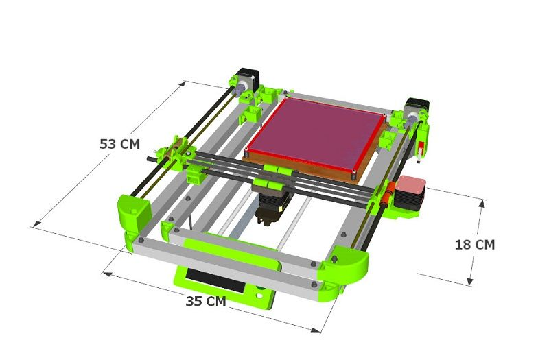 Typically, the inside of an FDM print is composed of infill, which have varying structures and shapes that can affect the print time, weight, strength and flexibility of 3D-printed components.
By default, most FDM slicer programs will produce parts with 18% to 20% infill, which is perfectly adequate for most 3D printing applications (using FDM). This infill percentage generally allows for faster and more affordable print runs.
Infill percentage
The strength of a design is directly related to a 3D-printed part’s infill percentage. A part with 50% infill compared to 25% is typically 25% stronger while a shift from 50% to 75% increases part strength by around 10%.
Infill percentages for FDM 3D printing can range from 18% and 20% (left) to 50% (middle) and 75% (right).Understanding the application of a final printed part allows a designer to specify the optimal infill percentage.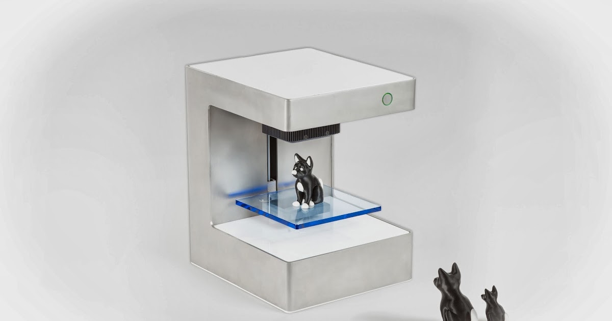 A prototype where the form is important can be printed with very low infill, which results in significant cost and time savings, whereas a bracket that will experience loading will need a higher infill percentage.
As mentioned above, the standard 18% to 20% that most FDM printers use as a default should be acceptable for most applications, though feel free to speak with a Hubs engineer for other potentially more robust infill options.
Feature strength
Infill also plays a critical role in how extended/protruding features are connected to a model. Snap-fit connections are a good example of this. The base of a snap-fit connection is often a weak point.
With a low infill density (20%), the cantilever is much more likely to break as the short extruded clip is only connected to the body of the print by a small cross-sectional area. Increasing the infill percentage means that more of the body of the print is connected to the cantilever, thereby increasing the strength of this connection.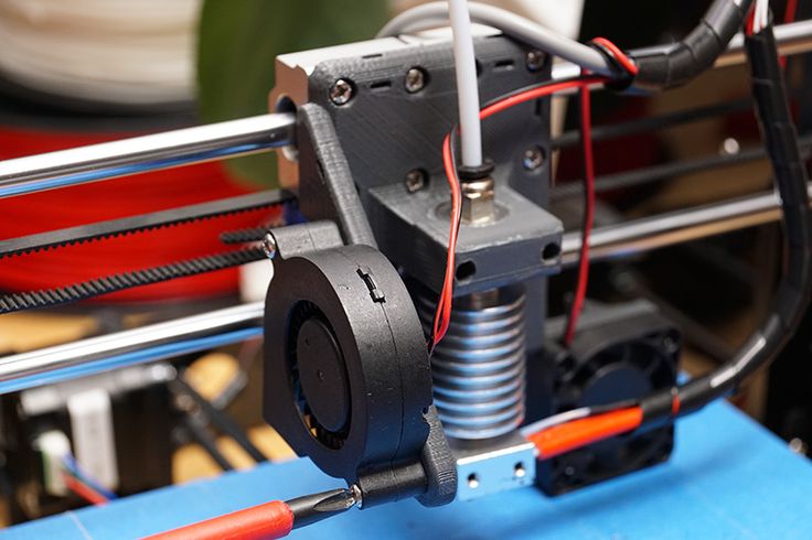
Screwing, tapping or bolting
An important factor to remember when choosing the infill percentage of your 3D-printed parts is whether you’ll need to drill holes or place screws into the component.
Consider a print with low infill that is going to be drilled and then screwed to another surface. Often the drill holes will go through the top and bottom layers of the print and miss the infill of the model, creating a very weak connection. For these applications, a higher infill is desirable (50% minimum).
Connections that utilize clearance holes and bolts are better suited to parts with a low infill percentage. The shells, walls, and infill offer good compressive strength providing better anchoring of the part.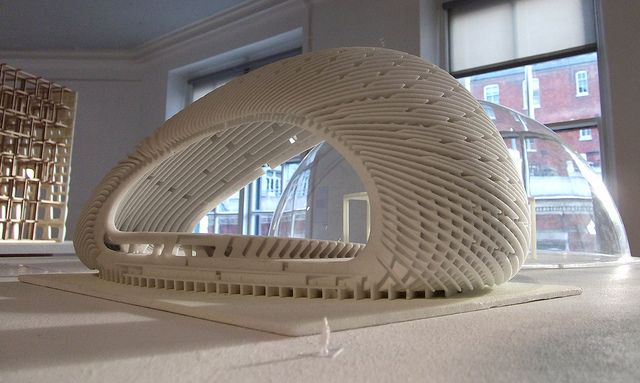
Infill geometry
For a standard FDM print, the machine will add the infill structure as an angled hatch or a honeycomb shape. Let's look at the four most common infill geometries and their optimal uses.
Rectangular - This is the standard infill pattern for FDM 3D prints. It's strong in all directions and is reasonably fast to print, and requires the printer to do the least amount of bridging across the infill pattern.
Triangular or diagonal - This geometry is used when strength is needed in the direction of the walls. Triangles take a little longer to print.
Wiggle - This geometry allows the model to twist or compress, as well as be softer.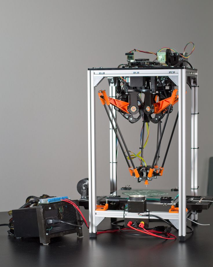 It can be a good choice, particularly with a soft rubbery material or softer nylon.
Honeycomb - This is one of the more popular infills. It's quick to print and is very strong, providing strength in all directions.
New to 3D printing or need a comprehensive refresher?
Get our guide to 3D printing
What are the best practices for setting shell and infill parameters?
Designing parts for FDM 3D printing involves a lot of steps, and it's easy to forget certain factors and features. Choosing the right infill percentages and geometries, and optimizing the use of shells, will definitely improve how your custom parts turn out.
-
Remember to take into account the application of the parts you're sourcing. This will affect the shell thickness and infill percentage you need to set. Increases in shell thickness and infill percentages lead to higher strength but also longer print times and augmented costs.
-
Design shells with multiple nozzle diameters.

-
If you need to place screws in a part, increase the shell thickness or infill percentage to improve anchoring. If this isn't feasible (or possible), consider using clearance holes and bolting with washers.
-
For cheaper rapid prints, rectangular infill is optimal thanks to its swifter print speed. Honeycomb or triangular infills boost part strength compared to rectangular geometries, so use either of these two if higher strength is critical to your part's functionality.
Curious about the cost of FDM 3D printing?
Our online FDM 3D printing service Upload a CAD file for a free, instant quote
Ready to transform your CAD file into a custom part? Upload your designs for a free, instant quote.
Get an instant quoteWhat do the characteristics of a 3D printer mean?
As I wrote the other day, I am currently writing a book on choosing a 3D printer.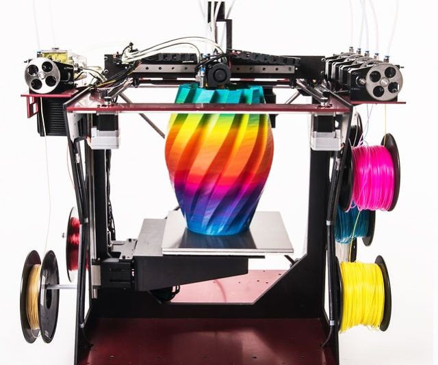 The working title is 'How to choose a 3D printer' In it I will tell you what to pay attention to first of all for a beginner. And what does this or that parameter mean. What are the schemes of 3D printers. And a lot of what is scattered over various discussions. Here the information will be compiled in one place. The book will be FREE, with free distribution.
Below is a draft of one chapter in which I will look at what the individual characteristics of 3D printers, which are published by equipment manufacturers and sellers, mean. nine0003
Using the Zenit 3D printer as an example, let's take a look at the 3D characteristics and I'll explain what they mean.
· Printable area: 240 x 215 x 230 mm
One of the main parameters. Tells us what is the maximum size we can print a part. In fact, the printable area is usually slightly smaller. And in reality, details of this size are not printed. Typically, a part can be larger than one of the sizes. But here we must understand that we can place the part diagonally on the desktop. Therefore, the maximum length of a part is usually limited by the length of the table diagonal. Although in some cases it is possible to connect a third dimension. But here we must already take into account the direction of the layers. nine0003
· X, Y axis positioning accuracy: 0.04mm
An important parameter that affects print quality. This is how accurately the printer can position the extruder over the printable area. Achieved with good mechanics. Tensioned belts. And greased guides.
· Positioning accuracy of the Z axis: 0.01mm
Also an important parameter that affects the quality. It depends entirely on the implementation of movement along the Z axis. There are different implementation options. We will consider them later. nine0003
Filament diameter: 1.75 mm
Parameter that tells us about the consumables used by the 3D printer. Now, in fact, there are two sizes of filament: 1.75 mm and 2.85 (3.00) mm.
1.75mm is now the most common. Such plastic is used by most 3D printers. All new materials first appear in this diameter.
2.85mm or 3.00mm older size. It is now used in 3D printers, Ultimaker clones and various homemade products. The original Ultimaker uses a diameter of 2.85mm. 3.00mm plastic is usually produced by "non-mainstream" manufacturers. And it is used in clones and DIYs. nine0003
There is no significant difference in usage between these standards. The only thing is that for 1.75mm there are more types of media offered for printing. Basic ABS, PLA plastics for both standard sizes are in stock.
There are also technical differences in the extruder scheme used. The so-called Bowden extruder is more adapted to the "thick" plastic 2.85 (3.00) mm. This is one of the reasons why 2.5mm filament is used in Ultimaker 3D printers equipped with similar extruders. nine0003
Nozzle diameter, mm: 0.3
Everything is simple here. The thinner the nozzle, the more accurately we can print the part. In theory. In fact, a thinner nozzle is prone to clogging. And starting with a diameter of 0.2 mm, this can be a serious problem.
The second reason is that as the nozzle diameter decreases, the print time increases. Here the dependence is linear - the smaller the diameter of the nozzle - it is necessary to go through more layers and passages in order for the walls to have sufficient strength. nine0003
As a result, the most common nozzles are 0.3-0.4 mm in diameter. They achieve decent accuracy. And the print time is quite adequate.
Larger diameter nozzles 0.5-1.0mm are commonly used in printers with a large printable area. With them, a speed is achieved that is more important when printing large parts than the quality of printing small parts of a model.
In most printers, the nozzles can be changed and the correct diameter can be used for the job. But in fact, by setting 0.3-0.4mm you will close 95% of all possible tasks.
· Layer height : 50 to 150 microns
Many manufacturers declare layer heights of even less than 50 microns.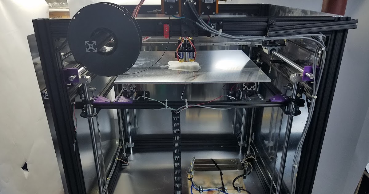 This is 0.05mm. For most, the lower limit is 50-100 microns. Here you need to understand - the thinner the layer, the more the printing time increases. That is, a part with a layer of 0.05 mm will be printed at least twice as long as a part with a layer of 0.1 mm.
Therefore, for most applications, a lower limit of 0.1mm or 100 microns is more than sufficient. nine0003
As for the upper limit of the thickness, there is also a dependence here. For high-quality printing, it is necessary that the layer thickness be no more than 0.5-0.6 of the nozzle diameter. That is, for a nozzle diameter of 0.3 mm, the optimal upper limit of the thickness, as indicated here, is 150 microns or 0.15 mm.
· Print speed: 40-150 mm/s
Print speed is a relative term and is usually achieved on large straight parts. The print speed is uneven and depends on many parameters. And the more complex the model, the slower the print speed. The average speed of most printers lies in the region of 50-100mm/sec.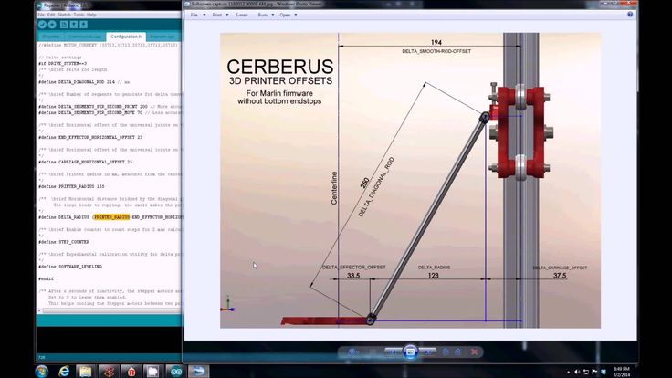 If a printer can't print simple parts well at 50mm/sec with standard PLA or ABS, there's something wrong with it. nine0003
As I said, super quality is usually achieved at 30-40mm/sec. This speed is selected either manually in the settings or the slicer itself (print preparation program) itself reduces the speed to adequate values.
· Maximum print head speed: 300mm/s
Parameter that affects print speed. It is indirectly related to the overall print speed.
Demonstrates the maximum speed at which the extruder can move "idle". In theory. nine0003
· Heated table: Yes
Another important option that caused a lot of copies to be broken. The presence of a heated table allows you to use almost all available materials for printing. First of all, with a large shrinkage. For example, one of the two most common materials is ABS. But here is a nuance ... Now there are quite a lot of materials that replace ABS in many tasks. If you do not plan to use such plastic, then you can get by with a table without heating.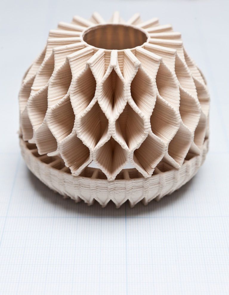 Conclusion - a table with heating is certainly better than without heating. But if you do not plan to use ABS in your tasks, then you can safely do without it. nine0003
· Number of printheads: 1
Most 3D printers have one extruder and this is also usually sufficient for the vast majority of applications. The second extruder makes it possible to use the dissolved material to create supports. For example, HIPS or PVA.
You can also print in two colors. But it almost didn't work out. And apart from demonstrating the possibilities, it is usually not seriously used.
In general, two-material printing got its momentum after the introduction of the PRO250 printer from PICASO. It uses an extruder with JetSwitch rotary nozzles. It allows you to achieve high-quality printing with two materials. And most importantly, he dramatically reduced the printing time with two materials. The fact is that when printing with two materials, when the extruders are located next to each other, you have to build an additional technological “tower” next to the part.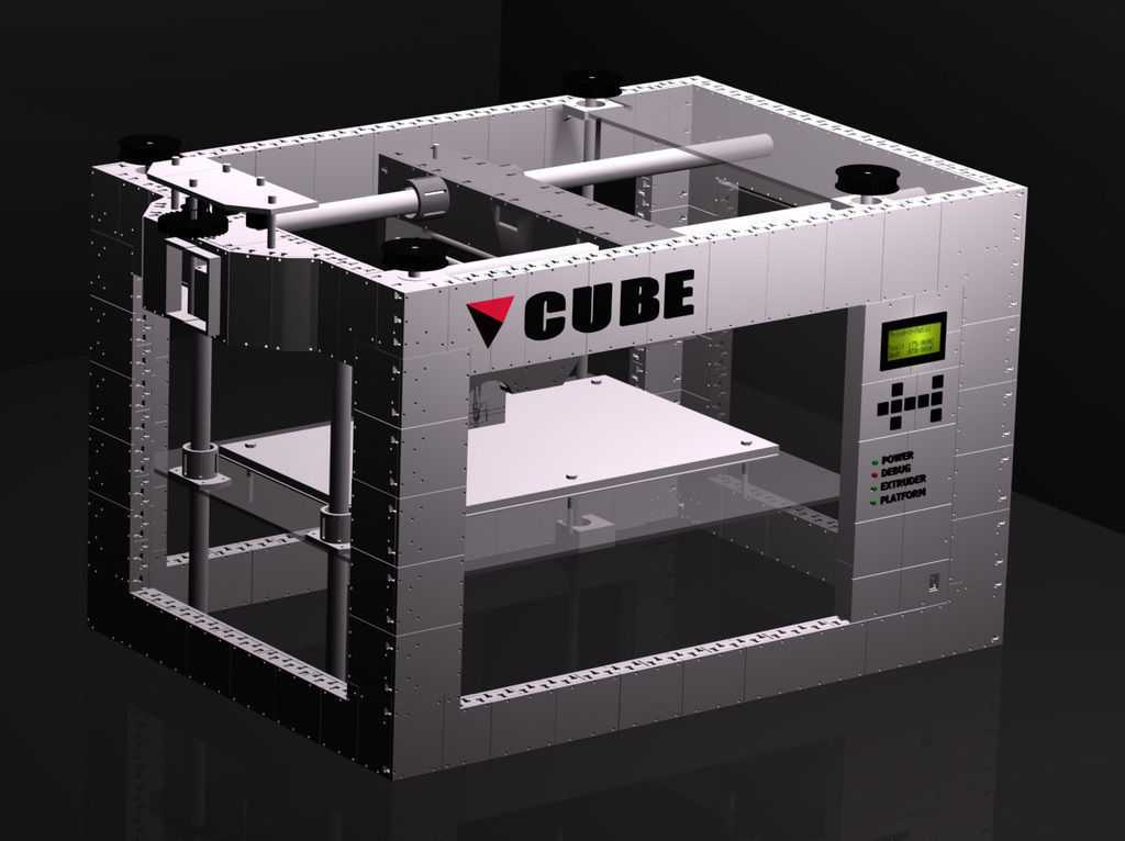 This leads to a significant increase in print time. Switching between extruders can take several minutes. nine0003
So if you don't need to print complex models, then you probably won't need a second extruder.
· Software : RepetierHost, Slic3r, Cura
With the exception of some 3D printers with their own software, most can work with universal programs. Both paid and free. These are Cura, RepetierHost, Slic3r, Simplify3D and many others.
Computer connection: USB
Most 3D printers connect to a computer using USB. Although more and more new models are appearing that also support connecting to the network using WiFi or Ethenet.
· SD card printing: Yes
This is the more important setting. Almost all printers have it. But there are still printers that cannot print from Flash or SD cards.
Why is this necessary? If possible, start printing using such memory cards. Printing via USB can lead to marriage. The fact is that the USB interface is quite dependent on the speed of the computer.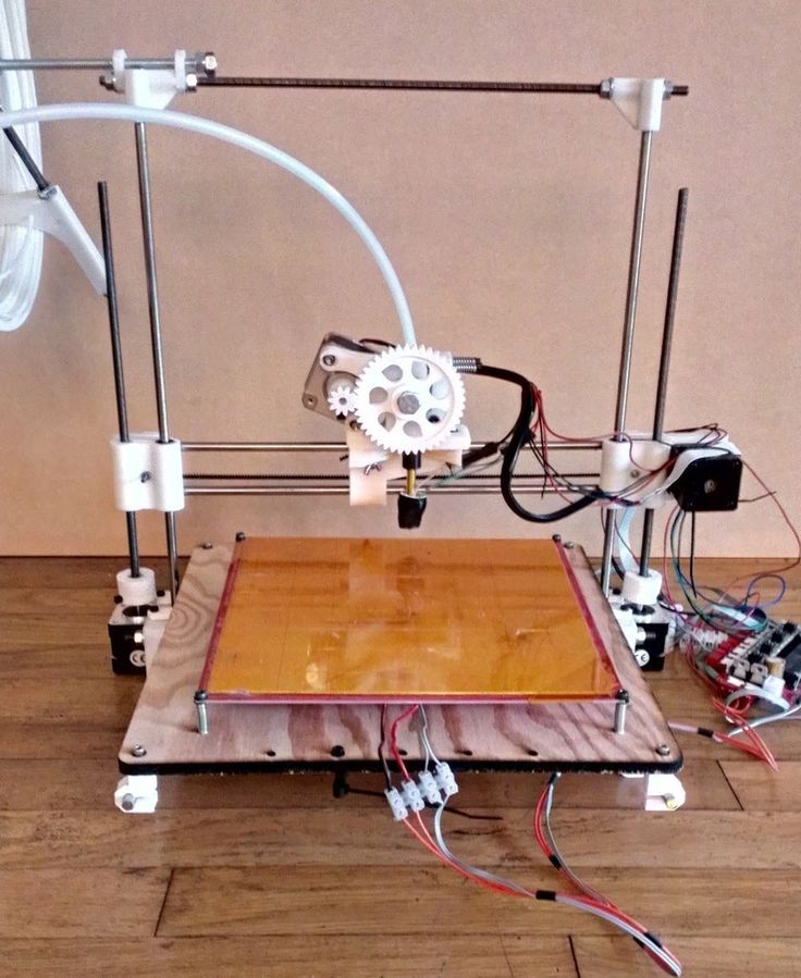 And if you load your computer with a “heavy” program at the time of printing, it is possible to “hang” it, which will lead to marriage. nine0003
· Dimensions: 460x360x370 mm
The parameter is only important for understanding where you can place the equipment.
· Weight : 20 kg
The same - it will help you choose a place for the printer. Although it’s probably clear that it’s not worth putting 20kg on a flimsy stool.
· Warranty: 3 years
Everything is clear here too. The bigger the guarantee, the better. Most printers now have a warranty of around a year. This, of course, is about printers bought in Russia, and not purchases from Ali. Some models have a two-year warranty. Or as in this case, even for three years. nine0003
Beaver everyone!
All current news from me in social networks.
My Instagram Like I'm on VKontakte If you like it, press "thumbs up".
3D printing in plastics, basic parameters
Plastics such as ABS and PLA have long been and will continue to be the most popular materials for 3D printing for a long time.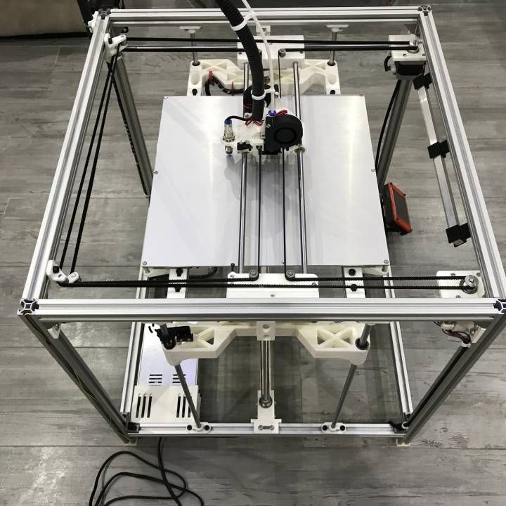 The main reason is their affordability in conjunction with relatively high strength characteristics compared to other materials. In this article, we will not delve into the reasons for the popularity of the plastics described above, fully describe their characteristics, or delve into the features of 3D printing technology. Here we want to highlight the effect of print settings/parameters and the position of the part on the printing platform, when printing with FDM (FFF) technology, on the final strength of the product. nine0003
You can learn about how a 3D printer works here, about 3D printing technologies (including FFF, FDM) and how they differ, here.
The strength characteristics of a 3D model can be affected by 3 main factors: layer thickness, filling and orientation of the model relative to the printing platform.
Layer Thickness
Layer Thickness is a configurable parameter that determines how much vertically (Z-axis) the furnace head moves when moving to the next 3d print layer. There are 4 standard sizes: 0.1, 0.15, 0.2 and 0.3 mm. There are smaller values, but, frankly, with a standard 0.4 mm nozzle, they make no sense (there will be no noticeable difference in quality). There are larger sizes, but they require a larger diameter nozzle. The typical value for this parameter with a typical 0.4 mm nozzle is 0.2 mm (200 microns). nine0003
First of all, it is worth mentioning that the layer thickness directly affects the surface quality (this is especially noticeable on surfaces slightly deviated from the horizontal or vertical), the lower the layer height, the higher the surface quality. This of course will depend on the type of printer, speed settings, etc., but we will not go into this. The higher the layer thickness, the correspondingly lower surface quality, while a simple transition from 0.2 to 0.3 mm will be noticeable. nine0003
Next, it is worth mentioning that the higher the layer height, the faster the printing and, accordingly, the less it costs. So 0.1 from 0.2 differs in speed by 2 times and in cost by 1.5-1.7 times.
And finally - strength. Without going into technical justifications, let's just say that the greater the thickness of the layer, the greater the overall strength of the product.
Infill
Infill in 3D printing with plastic is a configurable parameter that controls the amount of material and voids inside the outline of the model. nine0175 The outline of the model (default 1.2 mm) is the wall separating the outer space from the interior of the model. Since the printable models have a closed volume, when the print is finished, the interior space is completely hidden.
By default, the parameter is set to 12.5% (12.5% - material, 87.5% - void), which creates the required minimum strength. The higher the infill, the greater the weight and printing time of the model, and, accordingly, the cost.
For printing on plastics, you can choose any infill from 10 to 100%. It is better not to choose more than 90% to keep the minimum headroom for depreciation. Many tests have proven that 90% filling is stronger than 100%. The presence of free space inside adds additional strength under dynamic loads and object operation in changing conditions (for example, cooling-heating), due to the ability of the material to absorb into empty space. Moreover, 100% filling has a negative effect on the quality of the surface: small excesses appear on it plastic.
The relationship between filling and strength is simple: the higher the filling, the higher the strength. It is also worth remembering: the higher the filling, the greater the cost. nine0003
Location of the part on the printing platform
The location of the part on the working platform is controlled by the 3D printer operator and can significantly affect both the strength and the quality of the surface of certain areas. In some cases, this parameter is unregulated, since the very shape of the model dictates the only correct location.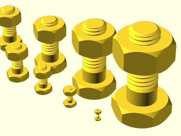 For example, a thin plane with a small relief on one side (a plate with letters) should not lie on a plane (and not stand on an edge) so that the letters are directed upwards. nine0003
One can probably write a separate article about the location of the part, since the quality of the surface from different sides will largely depend on the shape of the model and the presence / absence of support. To do this, you need to understand the principle of operation of the FDM (FFF) technology, you can find it here.
Effect of location on strength. For example, let's take a 10/10/1 cm parallelepiped. When printing "lying down" (the 10/10 cm plane is placed on the platform), the layers are located along the main plane. When printing "on edge" (plane 10/1 cm), the layers are arranged across the main plane. The strength of the model across the main plane will differ up to 6 times. (layers along the plane, the model is stronger). nine0003
Accordingly, when 3D printing, it is necessary to take into account which parts of the product should have greater strength and position the model accordingly.