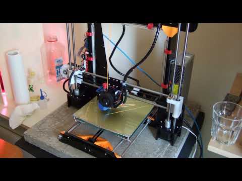
3D printer in action time lapse
How to create beautiful 3D print timelapse videos
We’re often asked how to make great looking time-lapses with a digital camera and our Original Prusa i3 3D printers. While OctoLapse is a good solution for some users, we’re using something a bit more special – a custom-made remote trigger, which is controlled by the Einsy RAMBo board. It’s not too difficult to make one and we’ll show you how to get started. However, if you would like something simpler and solder-free, wait until next week – we will show you how to make a Bluetooth shutter compatible with pretty much all modern smartphones.
WARNING: THIS METHOD REQUIRES YOU TO SOLDER A CUSTOM CABLE TO CONNECT A CAMERA TO YOUR 3D PRINTER – THERE’S A CHANCE OF POSSIBLE DAMAGE TO YOUR DEVICES IN CASE OF INCORRECT WIRING/CONNECTIONS!
A bit of theory
To record a timelapse of a print, a couple of things are needed:
- Original Prusa i3 MK3/S or MK2S / 2.
5 / 2.5S 3D printer
- A digital camera with a port for a remote trigger (power adapter recommended)
- Video editing software
- Custom-made cable (see below)
Our solution has some pretty good features: the cable can be made with just a few basic (and cheap) components, so it can be tailor-made to suit your setup perfectly. We’re using custom G-code to move the extruder aside and push the print bed all the way forward to have those clean, nice-looking shots. The cable is essentially a remote camera trigger, which is controlled by activating a pin on the Einsy / mini RAMBo. There’s one downside: remote shutters differ based on the camera manufacturer, so every cable will be slightly different depending on the camera model. The main difference is usually the connector, the way how the wires are connected and the voltages for the focus and shutter functions.
Some cameras have proprietary connectors, which usually means that you need to buy a pre-made remote trigger, disassemble it and modify it.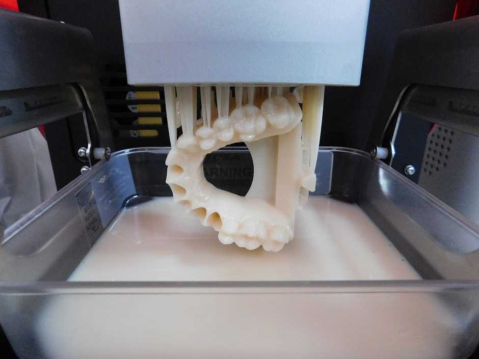
We’re using Panasonic Lumix digital cameras, so the sample cable described in this article is meant to be used with a Lumix camera. However, you can find a comprehensive list of popular camera brands at www.doc-diy.net along with diagrams depicting the parts required for making these cables. The way it works is pretty basic: three wires are all you need – ground, focus, and shutter. Once you connect the focus or shutter wire to the ground, the camera will perform the required action.
How a Lumix remote shutter works (by Doc-diy.net)
Making a cable for a Lumix camera
All cables will have two input wires: +5V and ground. We’re using a Toshiba TLP621 transistor as a switch to activate a separate trigger circuit, and an LED to check whether there’s power on the input pin. The “U2” part on the right is actually a 4-segment 2.5mm jack that will be plugged into the camera. The complete diagram is below:
If you decide to solder your own cable for a different type of camera, the parts to the right from the TLP621 will be different (namely R3, R4, R5, and U2).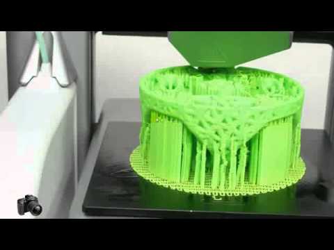
Here’s a complete list of all required parts for Lumix cameras:
- 2x jumper wire with a male connector – for MK3/S
- 2x jumper wire with a female connector – for MK2.5/S
- 2x 68k resistor
- 1x 2.2k resistor
- 1x 470 resistor
- 1x 1k resistor
- 1x LED
- 1x Toshiba TLP621 or another optocoupler with the same parameters
- 1x cable with a 2.5mm 4-segment jack (we recommend buying a 2.5mm jack with a cable already soldered to it for easier setup)
The total price for the needed parts is roughly 5-7 USD, but the overall price will be a bit higher since many of the parts can be bought only in larger quantities. You can even buy pretty good sets of various types of that part, so you have some extra stuff for future projects. 🙂
- Jumper Wire Set
- Resistor set
- LEDs
Connecting the cable to the MK3/S
We have designed the cable to fit the Raspberry Pi W Zero port on the Einsy RAMBo motherboard. As long as you are not using the RasPi, the port is free (and if you have a RasPi Zero, you are most likely going to use the OctoLapse plugin anyway).
There are two ways how to connect the wires to the RasPi port – either from inside the case or from the back. The choice is yours. We found it to be a bit easier to remove the back door from the case and connect the wires from the back. Just remember to do this when the printer is turned off!
Please refer to the illustrations below to learn how to connect the wires correctly
It’s always better to test the cable before you connect it to the camera. Simply run the modified G-code without the camera connected – the blinking LED will tell you whether the connections work.
Connecting the cable to MK2S / 2.5 / 2.5S
As described in the previous chapter, our solution is designed to work with the MK3/S primarily, since the cable is connected to the Raspberry Pi port, which is not present on older Mini RAMBo motherboards. With a very limited selection of pins, the easiest option is to disconnect the filament sensor and plug the timelapse cable in its place – see the illustration below.
Remember that you will need to use the latest MK2.5 firmware for the M42 Gcode to work!
This also means that the cable is connected to a different pin than in the case of MK3/S – it’s P20 instead of P73, so the G-code you’ll find in the next chapter needs to be modified. We’ll show you how.
Preparing the G-code
The best way how to create fluid timelapse is to take a picture after each layer. This is done by adding a piece of custom code to every layer change. Slic3r PE can do this for you.
The code we’re talking about is this (for MK3/S):
;AFTER_LAYER_CHANGE
G1 X5 Y205 F{travel_speed*60} ;Move away from the print
G4 S0 ;Wait for move to finish
G4 P500 ;Wait for 500ms
M42 S255 P73 ;Trigger
G4 P200 ;Wait for 200ms
M42 S0 P73 ;Untrigger
G4 P500 ;Wait for 500ms
;[layer_z]
In case you have an MK2. 5/S, you need to change the pin number to P20:
;AFTER_LAYER_CHANGE
G1 X5 Y205 F{travel_speed*60} ;Move away from the print
G4 S0 ;Wait for move to finish
G4 P500 ;Wait for 500ms
M42 S255 P20 ;Trigger
G4 P200 ;Wait for 200ms
M42 S0 P20 ;Untrigger
G4 P500 ;Wait for 500ms
;[layer_z]Let’s take a look at each step:
G1 X5 Y205 F{travel_speed*60} – this code tells the extruder to move all the way to the side and the print bed to move all the way forward
G4 S0 – waits until these moves are finished
G4 P500 – wait 500 milliseconds
M42 S255 P73 – M42 G-code activates pin 73 (P73) with 5V. S0 = 0V, S255 = 5V. Since we’re using fixed (manual) focus, we don’t need to worry about focusing the camera first
G4 P200 – wait 200 milliseconds
M42 S0 P73 – disabling (S0) pin 73, aka “untrigger”
G4 P500 – wait 500 milliseconds
After these actions are performed, the printer returns the extruder and print bed back to the original position and continues the print. This procedure won’t affect the look of the model in any way.
Adding custom G-code is easy. Open Slic3r PE, go to the “Printer Settings” tab and look for “Custom G-Code” section. Add the code above into the “After layer change G-code” textbox and save the profile as something easy to remember – e.g. Original Prusa i3 MK3S Timelapse. It’s advised to save this as a new printer profile, because when you slice an object with these settings, it will always perform the “move to the side” action after each layer, no matter whether a camera is connected or not. This, of course, makes the printing times noticeably longer.
Once you have the custom G-code implemented, you can slice the object as usual – you can choose any layer height or material.
Keep in mind that printing objects with the timelapse mode on will extend the print time noticeably.
Setting up the camera and preparation of the timelapse
To make a good looking timelapse video means first and foremost to ensure stable lighting conditions in the environment. If you have the printer located in a room where there’s a lot of sunlight and the lighting conditions change during the day (and people are often using light switches at night), the timelapse video will be extremely inconsistent.
A good solution is to place the printer in a dedicated room with minimum “traffic”. Sunblinds on a window are recommended. Set up artificial lights, so the 3D printer is nicely lit – we are regularly using “arch lamps” such as this one: https://www.thingiverse.com/thing:3469190 It’s easy to print and it creates some really good lighting conditions. And by the way, if you want to learn more about 3D printing and LED lights, check out our previous article!
Mount your digital camera on a tripod, change the focus mode to manual and push the print bed all the way forward – this will be the position where the printer will move the print bed during timelapse videos. Don’t zoom all the way in – you can easily do that in post-production.
Set up the camera and get it ready for shooting single photos (not a video). Keep in mind that longer prints can take many hours to complete, so using a power adapter is a good option. Otherwise, you may run out of batteries before the print finishes.
Turning photos into a timelapse
There’s a number of ways how to turn hundreds or even thousands of pictures into smooth videos. Most of them require a professional video editing software (such as Adobe Premiere Pro or DaVinci Resolve) and you can find plenty of tutorials for these programs online.
However, there’s a nice little app available for Windows directly on Microsoft Store. It’s called Time Lapse Creator, it has a simple interface and it’s completely free.
Time Lapse Creator is free and has an easy-to-use interface
Basically, all you need to do is to click the Select Photos Folder button and point the app to the folder where the timelapse photos are stored.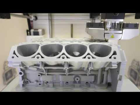 The length of the video is controlled by the number in the TimeSpan (ms) field – the number tells the app how long a single image should be displayed. Lower numbers will lead to faster speeds. Once you’re happy with the result, press the Save Video button to save the video as an MP4 file.
Other solutions
Using a DSLR camera and a custom-made cable turned out to be our favorite way of capturing timelapse prints. However, we understand that some users don’t have a digital camera, or don’t know how to solder. In our next article, we will show you some other solutions on how to create a print timelapse – with a regular smartphone and no soldering whatsoever. Stay tuned and don’t forget to share your timelapses on social media. Also, check out our Weekly Prints page where we publish new timelapse videos every week!
Learn How to Make a 3D Print TimeLapse – Phone or Camera – 3D Printerly
Many people wonder how to create those awesome timelapse videos that they may have seen online, and it isn’t as hard as you think. If you want to learn how to make some cool 3D print timelapse, you are in the right place.
Keep on reading through this article to learn how the experts make time lapses that you can be proud of.
How to Make Smooth 3D Printing Time lapse with a Phone or Camera
To make a timelapse you’ll need a digital camera or phone, a printer, a remote shutter, a mount to hold the remote shutter, a trigger, and video editing software.
First, you will need to set up your printer, preferably in a dark area in your workstation. This is because it is more controlled and will prevent flickering.
Next, you need to print the mount that will hold your shutter in place if you’re using a digital camera or earphones if you’re using a smartphone for taking photos. You also need to print the trigger that will be placed on the print head.
Mount all the printed parts onto your printer. Position the remote shutter for the camera on the 3D printed mount. For the smartphone, position the earphones on its 3D printed headphone mount.
Mount the trigger in the right place on the print head so it can move and press the shutter or the button on the earphones each time it goes to the stop position.
Place the camera or smartphone, whichever is taking the timelapse, in a suitable position. There should be no obstructions so it can take the photos seamlessly.
On the printers LCD, determine where the exact position the print head should be in (the stop position) before any photo is taken. Calibrate the printer to a position where the trigger mounted on the extruder clicks the remote shutter or button on the headphones.
Inject the correct gcode into your slicing software to enable the print head to stop after every layer is completed in order for a photo to be taken. The gcode also specifies your 3D print timelapse interval.
The end result will be a compilation of photos that you can stitch together using a video editing software to turn your still photos to a timelapse video.
For a more detailed explanation you can check out this video.
In this method, you get your 3D printer timelapse using a Raspberry Pi and the OctoPrint software.
OctoPrint is a remote control and monitoring software that you can install on Raspberry Pi. On the other hand, OctoLapse is a plugin that creates stabilized time lapses of your 3D printer in action.
First, download the latest OctoPi program and install it to your Raspberry Pi. Connect the Raspberry Pi to the 3D printer via USB and power it.
Install the OctoLapse plugin by clicking on the Octoprint settings icon, navigating to the plugin manager and installing it. You will need to restart the OctoPrint software before you can start using the Octolapse plugin.
Get a webcam e.g. a Raspberry Pi camera and hook the other side of its cable to the Raspberry Pi to get a working webcam stream.
3D print a camera stand, glue it to a sturdier pedestal and position the camera properly to get a good stream image. Also, adjust the focus of the camera.
You can adjust the OctoLapse 3D printing settings, to set your desired 3D print timelapse interval.
Upload the gcode locally to the OctoPrint software and hit print. You will notice that the OctoLapse 3D printing software will work fine. It will move the print head and bed to a fixed position after every layer for the camera to take a picture.
After the print is complete, the OctoLapse 3D printing software spats out a complete video file that you can download.
For a more detailed explanation of using OctoPrint to create 3D printing time lapses, have a look at this video.
How to Use Resinlapse to Make Resin Time Lapses
Filament 3D printers get most of the attention with time lapses because they have had more time to be fine-tuned, though resin time lapses are starting to make their way into the field.
One of the simplest ways that you can capture a high quality resin 3D print timelapse is to use a product called Resin Lapse, made by Uncle Jessy, a well-known YouTuber.
You can find the Resin Lapse product on Uncle Jessy’s Resin Lapse Big Cartel page for just $20 at time of writing.
Along with the Resin Lapse, you’ll need your resin 3D printer of course, along with a camera that supports a TRS shutter release and a decent video editing software.
You’ll usually find that most Canon cameras have this needed shutter release.
To start off, you need to take the photosensitive end of the resin lapse and insert it into an opening on your resin 3D printer. This is to enable it to trigger the camera to take a photo each time a layer of your print is processed.
Next, you insert the other end of the resin lapse cable into your camera. Place the camera in a stable position where it can capture the perfect view during the printing process.
After getting everything into place, start your resin 3D printer. Each time your printer finishes a single layer, the camera takes a picture. This process is perfectly synchronized.
You can then use a video editing software to stitch the images together to form a Resin lapse.
Example of video editing software that people use? Should be in the video guide I’m guessing.
To get a more detailed explanation of this process check out this video.
Best Camera for Time LapsesCanon EOS 77D
This camera is a beast when it comes to creating smooth time lapses.
The Canon EOS 77D has an optical viewfinder which enables you to view what you want to photograph exactly as the camera sees it in different lighting conditions. You can view your 3D prints with minimal lag and glare because this camera gets it in focus quickly.
When it comes to capturing images, the canon EOS 77D offers high speed continuous shooting. It can capture as much as 6 frames per second. It will not miss any moment in your 3D printing process.
It has HDR movie and timelapse movie modes. The latter takes photos for a long period of time and stitches it together to form a single high-speed video.
The former captures under-exposed and exposed images and blends them into a more detailed video. This feature will ensure that the timellapse on your 3D printer, whether it’s a Prusa or Ender 3D printer be excellent.
If you don’t have a workstation with optimal lighting conditions, then the anti-flicker shooting function will come in handy. It will enable you to take continuous shots without disparities in color or exposure since the camera compensates for flickering light.
For powering the camera, you have a DIGIC 7 image processor which will provide high quality and detailed results even in bad lighting conditions.
One satisfied customer from Amazon was impressed with how fast the camera captured images. She said that she was able to take 10-12 shots of her kids in a few seconds by just pressing the shutter quickly.
Another user ranked the Canon 77D over the Nikon especially when it comes to the autofocusing system. This enable to capture detailed images of his car without any flickering.
An Amazon user gave it a five-star feedback and said that it had a better sensor, resolution and CPU as compared to other cameras in the market. One person even won awards through using this camera, so that definitely counts for something!
You can get the Canon EOS 77D from Amazon today.
three and a half houses in four days / Sudo Null IT News Photo: 3dprintingmedia.network
One 3D printed house per day
Visitors to the Bautec International Building Exhibition, held from 18 to 21 February 2020 in Berlin, were given a unique opportunity to see the process of creating a residential building in one day thanks to 3D printing technology. Danish 3D printing construction company COBOD has teamed up with PERI Group on an ambitious project to demonstrate how a 3D construction printer can print a house in less than 24 hours. nine0005
During the exhibition, COBOD and PERI successfully printed 3.5 houses of 64 square meters each. The fourth house was not completed because the partners also had to create two 3D printed logos for the Bautec exhibition. Overall, COBOD claims that 3D logo printing is equivalent to printing 8 square meters of a house per hour.
Visitors to Bautec could watch the BOD2 large format printer in operation from 9:00 am to 5:00 pm. Time-lapse video from each press day is now available for those who were unable to attend the event in person. nine0005
Henrik Lund-Nielsen, COBOD CEO:
“By demonstrating the possibilities of real-time 3D printing, we wanted to prove that our BOD2 3D printing technology is ready for the global market, because it has enough quality, speed, reliability and stability to run smoothly, hour after hour, day after day, and with incredible productivity that surpasses traditional construction methods.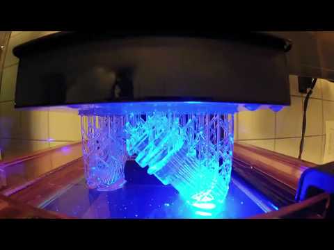 We planned to print 4 small houses in 4 days, and we almost reached our goal. Every day we printed one small house, but on the last day, at the request of the exhibition organizers, we decided to print a couple of company logos on a large scale, which subsequently did not allow us to complete the construction of the last, 4th house. nine0004
With a modular print design up to 15m wide and 10m high, the BOD2 3D printer has an unlimited build length, allowing it to build full-featured homes on site. For the Bautec show, partners COBOD and PERI installed a relatively small BOD2 configuration, measuring 5×5×5 meters, which is smaller than the rest of the BOD2 printers that COBOD sold to various customers.
Source: 3dprintingmedia.network
In terms of speed, the BOD2 is theoretically capable of printing up to 100 cm/sec, but due to the limited materials available for building 3D printing and the complexity of pumping mechanisms, the printer can only print at speeds of 40 cm/sec. At the COBOD exhibition, they refused to demonstrate the maximum speed for safety reasons.
Tilmann Auch, COBOD Product Development Engineer:
“Of course, we would like to show people a more powerful 3D printer for construction, but full-fledged printing on the exhibition site turned out to be impossible for several reasons. Therefore, we could only print small houses with a perimeter of 4 × 4 meters and with one bedroom. As for speed, here we have already limited ourselves. During the Bautec exhibition, we printed at a speed of no more than 25 cm/sec. This is due to EU requirements for machinery and robotics, which require the construction of a protective fence around the printer if we decided to print faster. We certainly didn't want to put up a fence at the show, as that would prevent visitors from seeing the printer in action." nine0004
Despite the limitations, COBOD and PERI were able to successfully print houses within the first three days, demonstrating the technology's ability to build the walls of a small house in about eight hours. At this printing speed, a 150-square-meter house can be reproduced in less than 24 hours, according to COBOD representatives.
Dr. Fabian Meyer-Brötz, leader 3D Printing Department at PERI Group:
“At Bautec, we proved to visitors that with a minimum number of workers, we can print houses with rounded walls at an average speed of 8 m2 per hour. It is important to note that these possibilities for creating arbitrary shapes allow not only to embody any imagination of the architect, but also to increase the functionality of the walls, to create improved designs of buildings and houses. We are not aware of any other technology that could provide the same result.” nine0004
The German construction company PERI Group has been investing in COBOD projects for a long time. In 2018, the company acquired a minority stake in COBOD, and in April last year, PERI Group was named the official distributor of the COBOD construction 3D printer.
Source: 3dprintingmedia. network
Learn more about 3D printing in the construction industry from our articles:
0006 Printing houses on a 3D printer in Russia, China and other countries,
Spetsavia: Russian building 3D printers and
Robotics in construction.
Comparison of 3D printing technologies: FDM, SLA and SLS
Additive manufacturing or 3D printing reduces costs, saves time and expands the technological possibilities in product development. 3D printing technologies offer versatile solutions for applications ranging from rapid concept and functional prototypes in the field of prototyping to fixtures and clamps or even final parts in manufacturing. nine0005
Over the past few years, high resolution 3D printers have become more affordable, more reliable and easier to use. As a result, more companies have been able to use 3D printing technology, but choosing between different competing 3D printing solutions can be difficult.
Which technology is right for your needs? What materials are available for her? What equipment and training is needed to get started? What are the costs and payback? nine0005
In this article, we take a closer look at three of today's most well-known plastic 3D printing technologies: Fused Deposition Modeling (FDM), Stereolithography (SLA), and Selective Laser Sintering (SLS).
Choosing between FDM and SLA 3D printer? Check out our detailed comparison of FDM and SLA technologies.
Download this high resolution infographic here.
VIDEO MANUAL
Can't find the 3D printing technology that best suits your needs? In this video tutorial, we compare Fused Deposition Modeling (FDM), Stereolithography (SLA), and Selective Laser Sintering (SLS) technologies in terms of the top factors to consider when purchasing. nine0005
Watch Video
Fused Deposition Modeling (FDM), also known as Fused Filament Manufacturing (FFF), is the most widely used form of 3D printing at the consumer level, fueled by the rise of consumer 3D printers. On FDM printers, models are made by melting and extruding a thermoplastic filament, which the printer's nozzle applies layer by layer to the model being built.
The FDM method uses a range of standard plastics such as ABS, PLA and their various blends. It is well suited for making basic experimental models, as well as for quickly and inexpensively prototyping simple parts, such as parts that are usually machined. nine0005
FDM models often show layer lines and may have inaccuracies around complex features. This sample was printed on a Stratasys uPrint FDM industrial 3D printer with soluble support structures (price starting at $15,900).
FDM printers have the lowest resolution and accuracy of SLA or SLS and are not the best option for printing complex designs or parts with complex features. Surface quality can be improved by chemical and mechanical polishing processes. To address these issues, industrial FDM 3D printers use soluble support structures and offer a wider range of engineering thermoplastics, but they are also expensive. nine0005
FDM printers do not handle complex designs or parts with complex features well (left) compared to SLA printers (right).
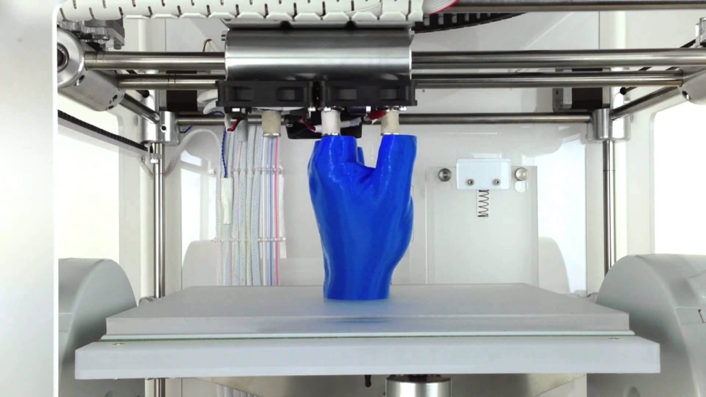
Invented in the 1980s, stereolithography is the world's first 3D printing technology and is still one of the most popular technologies among professionals today. SLA printers use a process called photopolymerization, which is the conversion of liquid polymers into hardened plastic using a laser.
See stereolithography in action.
Models printed on SLA printers have the highest resolution and accuracy, the sharpest detail and the smoothest surface of all plastic 3D printing technologies, but the main advantage of the SLA method is its versatility. Materials manufacturers have developed innovative formulas for SLA polymers with a wide range of optical, mechanical and thermal properties that match those of standard, engineering and industrial thermoplastics. nine0005
Models created with SLA technology have sharp edges, a smooth surface and almost invisible layer lines. This sample was printed on a Formlabs Form 3 Desktop Stereolithographic 3D Printer (price starting at $3499).
SLA is an excellent option for making highly detailed prototypes that require close tolerances and smooth surfaces such as molds, templates and functional parts. SLA technology is widely used in industries ranging from engineering and design to manufacturing, dentistry, jewelry, modeling, and education. nine0005
White Paper
Download our in-depth white paper to learn how SLA printing works, why thousands of professionals use it today, and how this 3D printing technology can be useful in your work.
Download white paper
free sample
Experience Formlabs print quality firsthand. We will send a free 3D printing sample directly to your office.
Request a free sample
Selective laser sintering is the most common additive manufacturing technology used in industry.
Selective Laser Sintering (SLS) 3D printers use a high power laser to sinter fine polymer powder particles. The unsprayed powder supports the model during printing and eliminates the need for special support structures.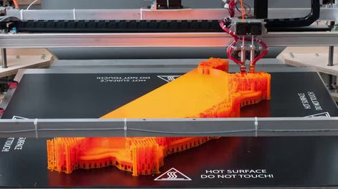 This makes SLS ideal for complex geometries, including internal features, grooves, thin walls, and negative taper. Models produced using SLS printing have excellent mechanical characteristics: their strength can be compared with the strength of injection molded parts. nine0005
Models created with SLS technology have a slightly rough surface, but almost no visible layer lines. This sample was printed on the Formlabs Fuse 1 SLS workshop 3D printer (price starting at $18,500).
The most common material for selective laser sintering is nylon, a popular engineering thermoplastic with excellent mechanical properties. Nylon is light, strong and flexible, resistant to impact, heat, chemicals, UV radiation, water and dirt. nine0005
Due to the combination of low part cost, high productivity and widely used materials, SLS is a popular method of engineering functional prototyping and a cost effective alternative to injection molding in cases where production runs are limited.
White Paper
Looking for a 3D printer to create durable, functional models? Download our white paper to learn how selective laser sintering (SLS) technology works and why it is popular in 3D printing for functional prototypes and end-use products. nine0165
 nine0172
 Either way, you should choose the technology that best suits your business. Prices have dropped significantly in recent years, and today all three technologies are offered in compact and affordable systems.
3D printing costing doesn't end with initial equipment costs. Material and labor costs have a significant impact on the cost of each part, depending on the application and production needs. nine0172
INTERACTIVE
Try our interactive ROI tool to see how much time and money you can save by printing with Formlabs 3D printers.
Calculate savings
FDM, SLA and SLS printed ski goggle frame prototypes (left to right).
We hope this article has helped you narrow down your search for the 3D printing technology best suited to your needs.