Diy fast 3d printer
Best DIY 3D Printer Kits & Build Plans 2022
Building your own DIY 3D printer can be an affordable option to get started 3d printing as well as a learning experience as one gets familiar with the mechanics or the nuts and bolts of a 3D printer. You learn how it works and how to fix it when it breaks. Building a 3d printer is more challenging than buying a completely assembled machine that’s ready to print. In this article, we review the best DIY 3d printers and list some of the options available. Here’s a guide for the list of considerations when planning your 3d printer build.
- Documentation & Assembly Guides
- DIY Kits vs Pre-Assembled 3D Printers
- Self-Source Parts vs DIY Kits
- Documentation
- Community
- Build Volume
- 3D Printer Kinematics
Table Of Contents
- DIY 3D Printer Build Advantages
- DIY 3D Printer Build Disadvantages
- DIY 3D Printer Kits vs Pre-Assembled Printers
- Complete 3D Printer Kits vs Open Source Build Plans
- Self-Source Parts
- Advantages of Building Your Own 3D Printer
- Challenges In Building Your Own 3D Printer
- Open-Source 3D Printers & Build Plans
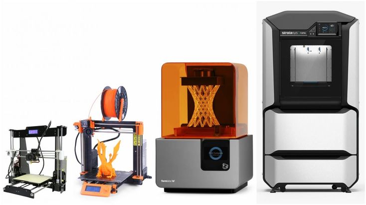
- 3D Printer Kits vs Pre-Assembled
- Complete 3D Printer Kits
- Self Sourced DIY 3D Printer Plans
- Railcore II 300ZL
- Pros & Cons
- Hypercube Evolution – H.
E.V.O.
- Voron 2.4
- Rat Rig V-Core 3
- The Evolution of The RepRap Project
- Self-Source Parts vs DIY Kits
- Cantilever Bed vs 3-point Bed Leveling
- Lead Screw vs Ball Screw vs Belt Drive
- Lead Screw vs Belt
- Lead Screw Pitch & Required Torque
- Build volume
- Rods vs Linear Rails
- White Knight: DIY Conveyor Belt 3D Printer
- Best Large DIY 3D Printers 2022
- Modix BIG-40
- Raise3D Pro2 Plus
- BigRep – STUDIO G2
- Piper 2: Piper 3D Printers Made From Conduit Pipe
- Gantry 3D Printer Design – Reducing Moving Mass
- Large Scale 3D Printing vs Batch Printing
DIY 3d printer plans make it easier to get started and are a great option for beginners who want to learn how the mechanics work. The kits usually come with everything you need such as tools, parts, and instructions which take out some of the guesswork when building your printer.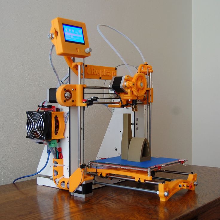
Building a printer can be challenging and time-consuming. There are many things that can go wrong, so it’s important to have some experience with building or repairing electronic devices before starting this project. Also, you may not have all the parts you need, which could lead to delays in printing.
DIY 3D Printer Kits vs Pre-Assembled PrintersThere are pros and cons to each option. If you choose a kit, it’s important to consider how much time you have for assembly, the difficulty level of the project, your budget, versatility options (e.g., build volume or filament types supported), and the quality of the community support.
Complete 3D Printer Kits vs Open Source Build Plans
While many printer designs are available in complete kits some open source designs are currently still self-sourced, meaning that builders will have to source individual 3d printer parts and get it all together which results in complexity as some parts may take long to receive and increases the chance that one might order the wrong part number. With that said, is the price still about the same depending on extruder options print size.
A common option is to source all your own parts. This can be more affordable, but it takes more time and effort to find compatible parts and can be difficult depending on experience level. The advantage of this approach is that you can customize your printer to fit your needs.
Advantages of Building Your Own 3D PrinterThere are several advantages of building your own DIY printer:
- -You learn how the machine works and can troubleshoot problems on your own.
- It can be more affordable than buying a pre-assembled printer.
- You can customize your printer to fit your needs.
- The community is usually very helpful and supportive.
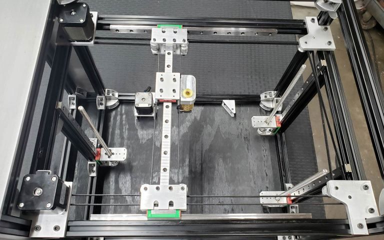
DIY Printer Build
Challenges In Building Your Own 3D Printer
There are also some disadvantages of building your own printer:
- It can be more challenging than buying a pre-assembled machine.
- There’s a higher chance of something going wrong during the build process.
- You may not have all the parts you need, which could lead to delays in printing.
The best DIY printer for your needs depends on your level of experience, budget, and goals. We hope this article provides some helpful advice for choosing the right printer kit for you. Happy building
Open-Source 3D Printers & Build Plans
Documentation is important when choosing a 3d printer to build or buy and effects overall user experience. Poor documentation can lead to downtime as users assemble or troubleshoot their machine to get it printing. Look for kits or build plans that are well documented and comprehensive for your skill level. Good documentation will also include tips and tricks for getting the best 3d prints, troubleshooting common problems that you may experience.
3D Printer Kits vs Pre-AssembledWhen it comes to the Best DIY kit printers, there are many options. The advantages of a pre-assembled machine is that they usually come with some documentation and have been assembled by someone else so you can trust in them being functional machines already. This makes them less complicated than self sourced kits and more appealing to beginners.
If you’re not comfortable with sourcing your own parts from various suppliers, there are also pre-assembled printers available. These machines come with everything or almost everything to assemble a working machine, including all of the screws and tools needed.
Complete 3d printer kits make it easier to get up and running rather than sourcing all the parts yourself from different suppliers with different shipping dates or quality. It is also a great way of saving money on shipping which can be quite costly when buying small amounts of parts.
The downside of a pre-assembled machine is that they can be more expensive than DIY kits, lack upgradability, and might not have the best quality control.
When sourcing your own parts for a printer there are a few things you need to take into account: what type of printer do you want to build, what parts do you need and where can you source them from.
The best 3d printer kits give a great range of options depending on performance needs and budget. Beginners can start off with an unassembled diy kit which is less expensive than pre-assembled machines.
Railcore II 300ZLThis is a pre-assembled machine that comes with an excellent build guide and video tutorial. It uses a CoreXY motion system which gives it good print quality and speed.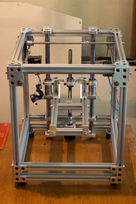 The kit can be sourced from different sellers, or you could buy the fully assembled machine directly from Printed Solid.
Each of these kits have their own pros and cons, so it’s important to do your own research before settling on a printer. For example, the Rat Rig V-Core uses a corexy kinematics which is known for its speed and accuracy, but can be more difficult to calibrate.
Original Prusa i MKS+
This kit is based on the popular Original Prusa i MKS printer and comes with an excellent build guide. It’s a great option if you want to get started right away with minimal assembly.
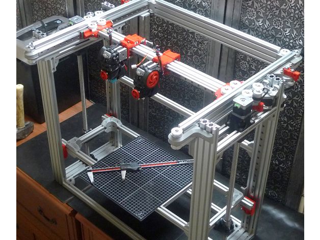
Hypercube Evolution – H.E.V.O.This kit is a great option for those looking for an upgradeable machine. It comes with a variety of parts that can be swapped out or upgraded as needed.
Voron 2.4This open source design is great for experienced builders and offers good print quality and speed.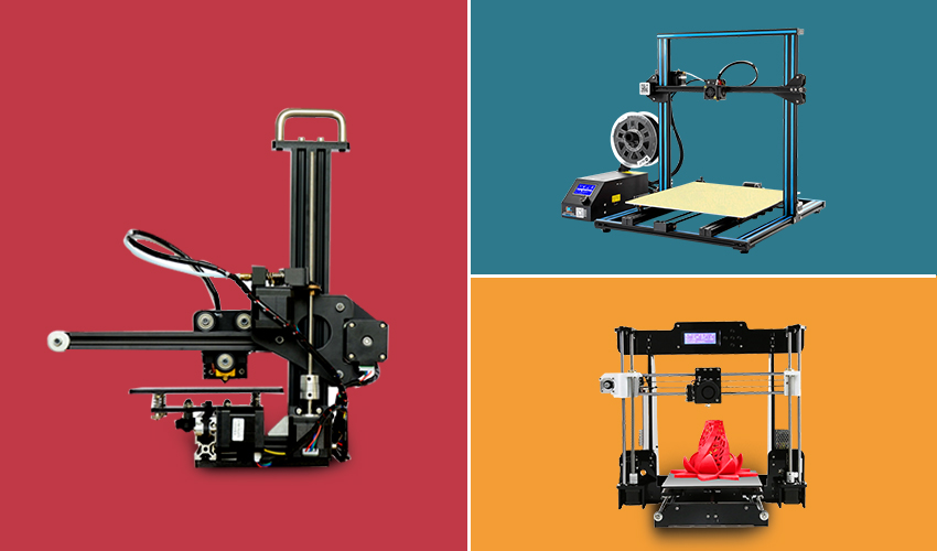
When sourcing your own parts, it’s important to do your research and decide which seller to use and consider shipping rates.
Rat Rig V-Core 3The Rat Rig V-Core 3 is a great option for those looking for a specific size or options as kits can be configured for specific needs or price. The complete printer kit comes in a range of options with a well documented build guide and instructions. The V-core 3 uses the CoreXY motion system which offers good print quality and speed. The v-core 3 kit can be purchased from the Rat-Rig website, or could be self sourced.
The Evolution of The RepRap Project
Self-Source Parts vs DIY KitsWhen sourcing your own parts, there are a few things to take into account: what build volume is needed and type of parts to use which is usually related to how much you’re willing to spend.
There are a range of options for extruders and electronics, so it’s important to decide on the features you need.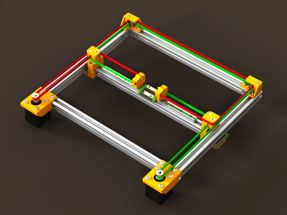 If you want a machine with high resolution, then you will need more precise parts which can be expensive.
Cantilever Bed vs 3-point Bed Leveling
While many of the original DIY 3d printers used cantilever beds to lift the print bed or build plate constrained POM wheels or smooth rods. The newer 3d printer designs use linear rails and have adopted more functional mechanisms such as belted z-axis, and non-planar 3d printing concepts such as 3-point bed leveling or tilting print beds. Although the simplicity of older Reprap 3d printers were less technical and easier for newbies, the increasing number of options and features can easily be adopted from corexy design platform to another, which has exponentially inspired contributors as they work to identify or fix potential issues or increase overall print volume.
Lead Screw vs Ball Screw vs Belt DriveMechanical components and kinematics are critical to the functionality and can compromise speed or quality. Lead screw which is commonly used to drive the z-axis or lift the print bed is known for backlash but backlash can be eliminated using anti backlash nuts or may not be an issue due to gravity. Lead screw pitch and lead is critical for speed and precision. Issues with speed, resonance, artifacts can be a challenge in any 3d printer build but can be reduced by travel speed and acceleration but is compromised with slower travel speed the longer it takes to print an object.
Quality lead screws and ball screws cost much more but cheap lead screws can have tolerance issues. Longer ball screws may wobble at a distance and need support and rigidity. Although backlash is mostly a problem in XY-axis movements while the z-axis is the preloaded weight of the bed and gravity.
Lead Screw Pitch & Required TorqueLead screws are similar to a gear. When the pitch changes the lead and torque needed to drive the system changes as well.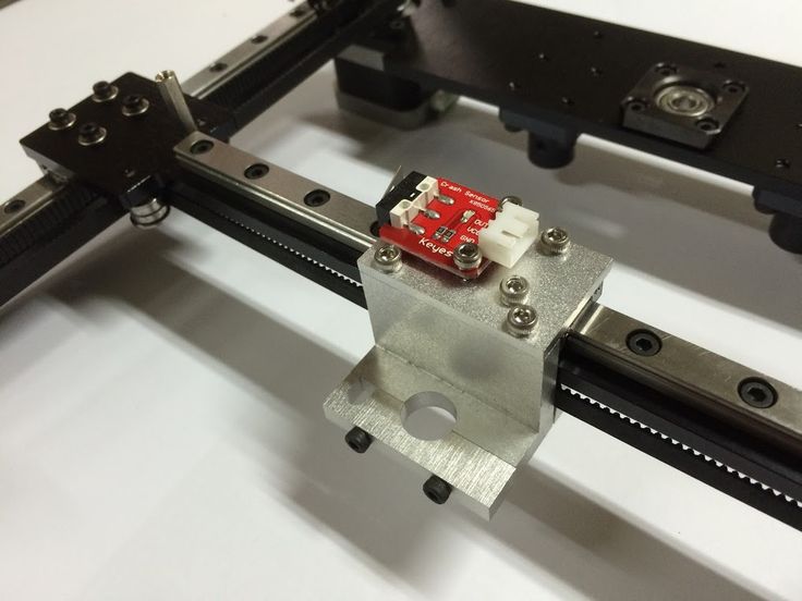 Most 3D printers use 1/16 or 1/32 microstepping but the resolution of 3d printed plastic can only be so precise. Larger motors have more inductance and need more voltage to reach the same RPM. Increasing the step rate for the reduced travel rate of the drive, a higher voltage stepper driver and supply may be needed to reach ideal motor performance.
Build volume
Build volume refers to the print bed size which dictates the maximum size of 3d printed objects.
Rods vs Linear Rails
Many of the earlier 3d printers were designed around cheaper mechanical parts such as carbon rods or stainless steel smooth rods which were once commonly used and recommended. As the cost of linear rails become cheaper and cheaper due to the economy of scale and increasing number of buyers and large volume production of manufactures and suppliers. 8mm steel rods and linear bearings are slowly being somewhat phased out but still used on cheap kits found on Aliexpress.
White Knight: DIY Conveyor Belt 3D Printer
The White Knight 3D Printer is a belt printer designed by Carl from NAK3DDesigns. The Unlimited Z-Axis has a large build area for continuous 3d printing.
Best Large DIY 3D Printers 2022
Large scale 3d printers are becoming more accessible to the average user as open-source designs continue to improve. One challenge of large scale 3d printing is bed leveling and layer adhesion Deciding on a large 3d printer to build or buy is a balance between price and reliability. In this section, we review and list the best large scale 3d printers available.
Large-scale 3d printing is increasing in demand as 3d printing becomes more accessible. Large scale printers allow users to 3d print large objects that would otherwise be constructed from multiple smaller printed objects from smaller machines.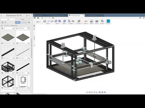
Modix BIG-40
- Made In Israel
- Build Volume 400 × 400 × 800 mm
- Price $5,000
Modix specializes in large format 3D printers that are available in DIY self-assembly kits, which is a much more affordable 3d printer compared to the larger commercial 3d printers on the market.
The Modix BIG-40 is an industrial grade machine that uses a dual-zone heated bed and a PEI print surface with auto bed leveling and an enclosure option.
Raise3D Pro2 Plus
- Made In US
- Build Volume 305 × 305 × 605 mm
- Price $5,999
- Extruder/Hotend Dual Extruder
Raise3D is known for their high quality 3d printers that are made in the USA. The Pro2 Plus is the latest release which offers the largest build volume compared to their other Raise3D models.
The Pro2 Plus has a 305 mm x 305 mm x 605 mm build area and reaches temps up to 300°C which allows users to expand their range of materials to print with.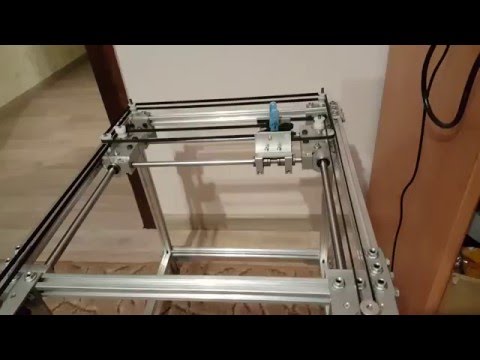
BigRep – STUDIO G2
Made In Germany
Build Volume 500 × 1000 × 500 mm
Price $60,000
The BigRep STUDIO is a large format 3d printer designed to print engineer grade materials and uses dual extrusion ruby nozzles for abrasive materials. The large machine is equipped with a dual filament chamber with each chamber independent controlled temperature environments and features a touchscreen interface and the BigRep BLADE software.
Piper 2: Piper 3D Printers Made From Conduit Pipe
Piper 2: Piper 3D Printers Made From Conduit Pipe.Piper 2 by Piper 3D Printers is a open source corexy DIY 3d printer design made from conduit pipe.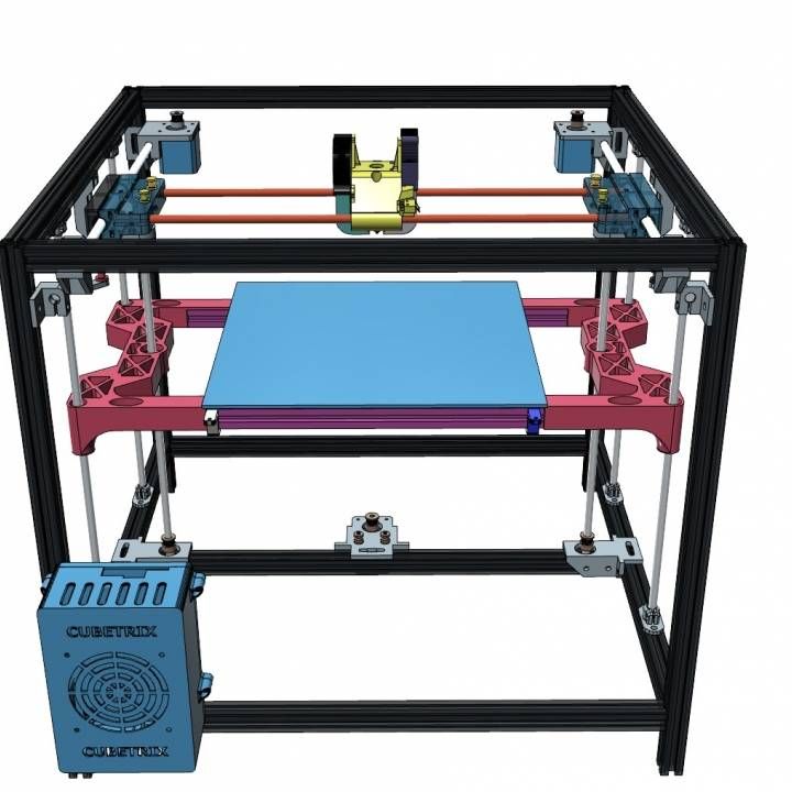
see Piper 3D Printers
see Midwest RepRap DIY 3D Printer Festival
Gantry 3D Printer Design – Reducing Moving Mass
Many earlier 3d printers kinematics use the classic “bed-slinger” design that originated from the early Reprap designs. As 3d printer builders and designers gradually pushed the limits of scalability, the classic y-axis traveling bed kinematics became more problematic. Although there are large scale 3d printers that work fine with this mechanical arrangement, they are often using industrial grade hardware such as linear rails and ball screws driven with high end servo motors to maintain print head position at all times, print beds that travel laterally, typically along the Y-axis.
While a simple and cheap solution for kinematics that works for countless desktop 3D printers, this potentially poses a challenge to a large-format 3D printer in that it’s putting a lot of moving mass on one of the two main axes engaged in travel during printing. A large moving mass consisting of the print bed, the carriage it’s riding on, and the increasing weight of the print being deposited on it means greater inertia to overcome with each direction change in that axis.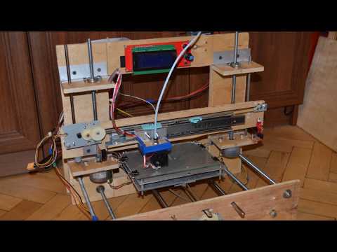
The timing belt tightness and the linear guides may be rigid enough to handle the inertia, but the frequent direction changes can leave artifacts such as ghosting on 3d printed objects. Not only this, a print that has poor adhesion to the print bed, moving vigorously back and forth through the Y-axis, can risk the success of the print.
These problems are not an issue for large-format 3D printers which use a static bed setup that is stationary and moving only through the Z-axis layer changes. While the motion system is more complex it can maintain the mechanical advantage compared to “bed-slinging” designs.
Large Scale 3D Printing vs Batch PrintingLarge volume 3d printers can be considered as a great solution for batch printing, or alternate to multiple smaller 3d printers. A typical sized object or print job can be arranged and stacked for mass production. However, a print farm can complete a large quantity run or job quicker than a single object 3d printed as a batch of 3d printed objects are spread across a number of machines and can decrease the number of failed prints.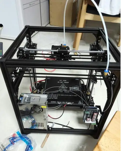 Failed prints are isolated to a single machine without affecting the rest or potentially ruining the entire job.
Like this:
Like Loading...
3D Print Speeds to Approach 1800 mm/sec, Thanks to REAL's 3D Printer Boards - 3DPrint.com
My biggest complaint, along with probably the majority of individuals who own a desktop 3D printer, is the lack of speed when it comes to fabricating an object. The typical desktop 3D printer, whether it’s an FDM/FFF or an SLA machine, prints at speeds which are typically in the range of 50-150 mm/sec.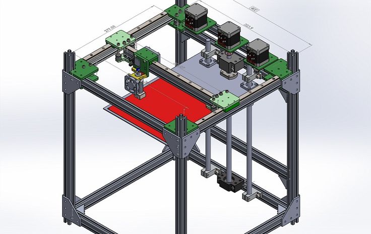 This means that the extruder (if an FFF/FDM machine) is able to lay down 50-150 mm of molten filament every second. This may sound quite fast, and in fact the movements are rather rapid, but the layer height of the extruded plastic is usually so small that such speed does not translate into rapid fabrication.
One company called Create it REAL, founded by a man named Jeremie Pierre Gay, and based out of Aalborg, Denmark, wants to change all this, and in fact already is in the process of doing so with the introduction of their 3D RTP (Real Time Processor) board. The control board, which can serve as the main brain for both FFF/FDM and SLA 3D printers, is incredibly advanced and built for speed, among other capabilities.
Create it REAL is offering the board as part of a development kit via their website, seeking 3D printer manufacturers as well as everyday enthusiasts who may want to upgrade their own printer’s capabilities. Currently the company says that the 3D RTP board is capable of putting out up to 450 mm/sec extrusion rates in machines which utilize it, while also providing other important features lacking in many 3D printers today.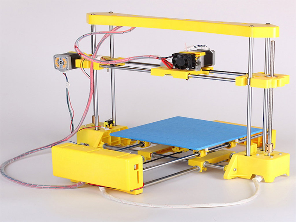
Back in February, we reported on Italy based Dynamo 3D, the first manufacturer to utilized these boards within a production run of their ONE EVO 3D Printers. This allowed the ONE EVO to print at speeds of up to 450 mm/sec, a key selling point within a market that’s hungry for improvements in the speed department. Although we haven’t tested the printer out ourselves, early indications seem to back up the company’s claims.
ONE EVO 3D Printer
What’s even more incredible may be Create it REAL’s future plans, as according to Fabbaloo, they claim that the 3D RPT board will soon be capable of handling print speeds approaching a staggering 1,800 mm/sec. No, this is not the travel speed, but actual print speed, meaning that prints which may take 4 hours (240 minutes) to print on a machine capable of printing at 180 mm/s, could be fabricated within just 24 minutes on future printers which utilize Create it REAL’s boards.
At these speeds, the developments we saw earlier this year pertaining to the rapid printing enabled by startup Carbon 3D’s CLIP technology, may just seem ordinary. There are some physical speed limits I imagine, especially when it comes to extrusion based FDM/FFF 3D printing, as the thermoplastic needs at least some time to cool before a subsequent layer is deposited. With that said, even these obstacles can likely be overcome with software tweaks and new materials.
In addition to speed, the company claims that the chip within the board has a surplus of processing power which can be exploited to eliminate a great deal of vibration during the print process. This is because the chip is able to perform calculations within nanoseconds, and adjust acceleration and movement to best suit the current print job.
If the company’s claims are legitimate and print speeds of up to 1,800 mm/sec are forthcoming, then there is little doubt in my mind that we will soon be seeing adoption of this board by some of the larger manufacturers within the industry.
We are only at the very earlier stages of innovation within the 3D printing space. The next several years are going to be incredibly exciting as progress continues to be made on several fronts.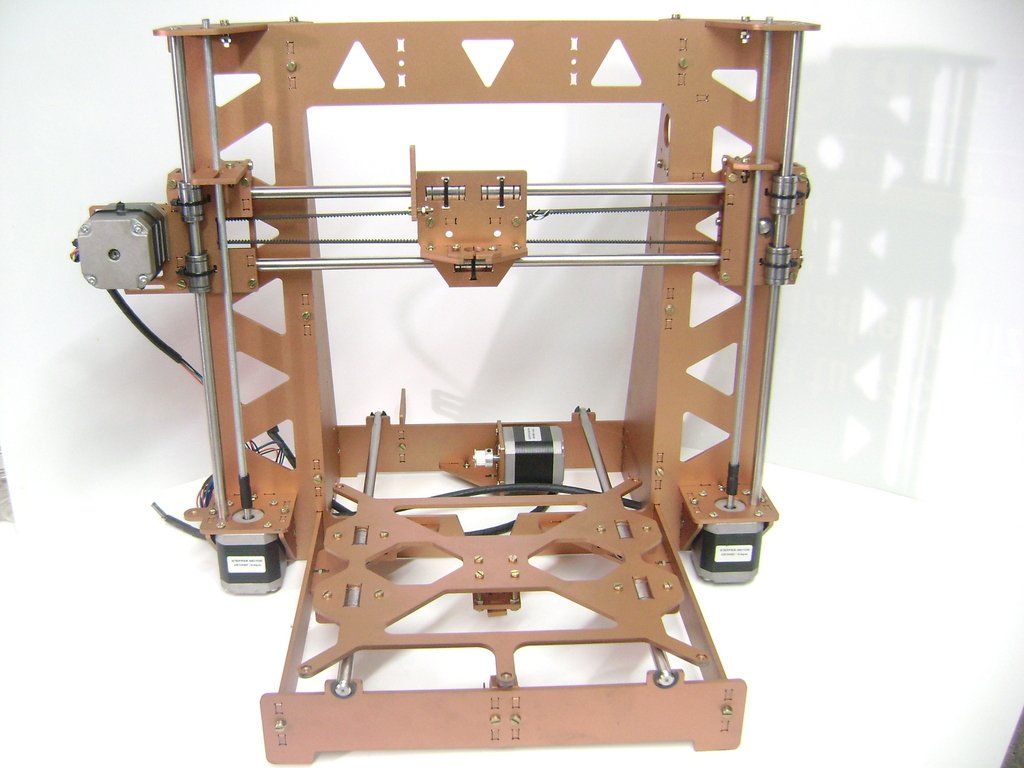 Let’s hear your thoughts on Create it REAL’s technology in the 3D RTP forum thread on 3DPB.com.
Stay up-to-date on all the latest news from the 3D printing industry and receive information and offers from third party vendors.
Tagged with: 3D RPT board • 3d rpt chip • Create It REAL • fast 3d printer • fast 3d printing
Please enable JavaScript to view the comments powered by Disqus.
Homemade metal 3D printer, but something went wrong / Sudo Null IT News
Hello everyone, my name is Sergey. In this article, we will talk about 3D printing with metal, more precisely, about my attempt to implement 3D printing with metal.
Very often, people who are interested in or engaged in any activity, no matter what, stumble upon something completely new and previously unknown to them, something that can help develop/improve their main activity. A similar situation happened to me. nine0003
Surfing the expanses of your Internet, I came across a wonderful technology for vacuum deposition of metals on various materials. On Habré there is an interesting article about this technology. In addition, on many other resources it was said that the evaporated metal moves towards the target in a straight line.
Many resources0003
And then I thought, what if I spray metal in the place I need, gradually increasing the thickness? I looked for information about whether someone did this - I did not find it.
Registered on a forum where sprayers gather together and began to disturb them with questions like: is it possible to build up a “film” with a thickness of 1 or more millimeters. To which I caught a lot of misunderstanding what it was for, but received a positive answer. nine0003
General information received, you can begin to prepare for experiments.
It is known from various articles and documents that a vacuum of no more than 10⁻² Pa is needed. For comparison, the order of magnitude - the pressure that gives a household vacuum pump (Value and others) - about 4 Pa (measured value), i.e. pressure is 400 times greater than necessary. How to deal with it and what to do? To achieve low pressures, turbomolecular vacuum pumps are used, they work in parallel with the foreline pump and, literally by molecules, capture the remaining air from the chamber. The process is not fast. The pump looks like this. nine0003
We installed a pump, it pumps out air and everything seems to be fine, but how to find out the pressure? For this I chose an ionization vacuum gauge.
In fact, nothing else is needed, except for the chamber and evaporator. I did not find a ready-made affordable (in terms of finances) camera, therefore, I decided to make my own. It is of a small volume (about 8-10 liters) in order for the air to be pumped out faster.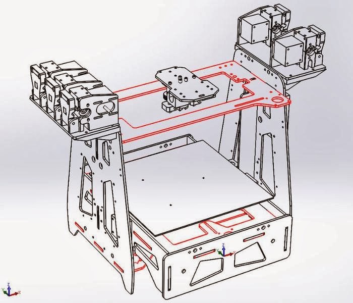 Usually, the chambers have a spherical shape, in my case it is, on the contrary, elongated, in order to be able to set the “target” (the place where the metal is deposited) at different distances from the evaporator. In addition, the camera has a lot of flanges for connecting all kinds of inputs/outputs and sensors. I modeled the camera in a well-known CAD program, drew drawings and transferred it to production. nine0003
Current leads and conductors I made from a brass bar and a brass rod, bought on the local market. (Juno, who is from St. Petersburg).
In the photo below, a tungsten boat is fixed between two conductors.
The bottom part looks like this. The photo shows the cooling tubes of the current leads. Subsequently, I abandoned them, due to the simplification of the system.
Assembling the camera did not take much effort and complexity. It is much more difficult to achieve vacuum retention in this chamber. To do this, I polished the flanges and all mating surfaces to avoid the slightest leakage through the rubber seal (in the photo below, I processed only the top flange).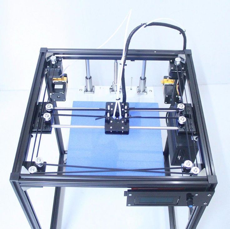 nine0003
As it turned out later, the weld is not airtight at all (meaning for low vacuum). I, out of inexperience, assumed that by pumping a pressure of 300 kPa into the chamber and immersing it in a bath of water, I would carefully find all the leaks and eliminate them. Yes, at the first stage I did just that, but the pressure in the chamber did not fall below 10-2 Pa, there were leaks. Interestingly, before the start of the test, at a pressure in the chamber of 300 kPa, bubbles emerged from the welds with an intensity of approximately 1 bubble (diameter 2-3 mm) in 30-40 seconds. And those were big losses that I eliminated. But what to do with minimal vacuum losses that cannot be tracked in "kitchen" conditions? nine0003
The solution was close. To do this, all you need is a mass spectrometer.
The idea is simple – the investigated chamber or container is connected to the vacuum chamber of the spectrometer. Air is pumped out, on the graph they look for extraneous peaks of any gases.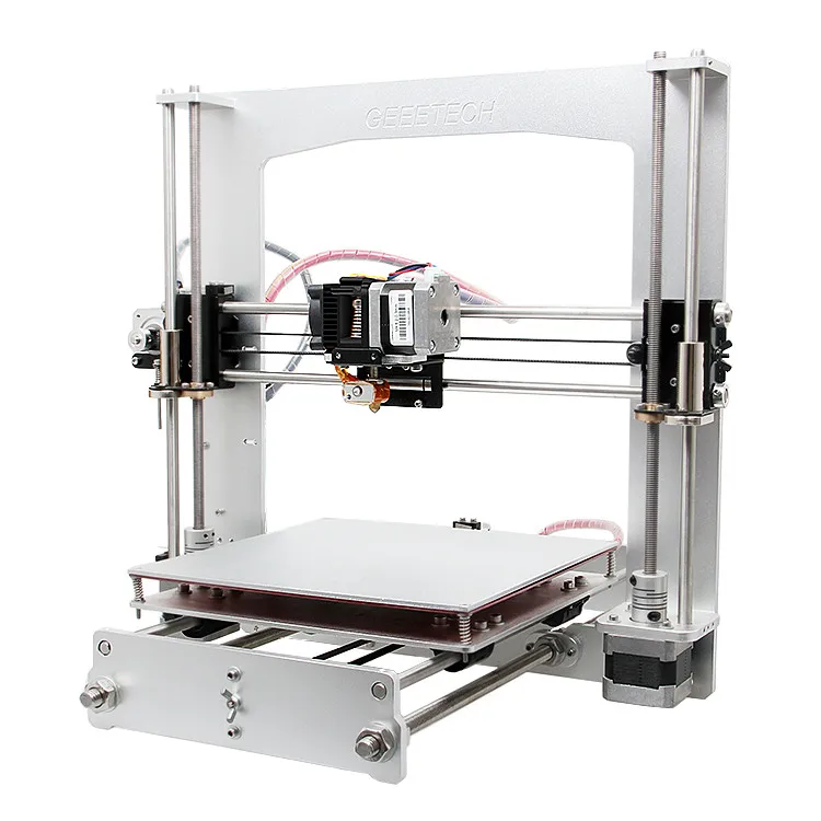 After that, helium is supplied locally, to the places of possible leakage. It is helium, because its penetrating power is higher and the helium peak can be easily tracked on the spectrum. As soon as helium enters the chamber through a micro-hole, it is immediately visible on the spectrum. nine0003
I drove twice and looked for leaks twice. Now the chamber with the installed pump is hermetic and it is possible to carry out experiments further, having previously assembled all the components of the system on the rack.
General view of the incredible installation.
Starting up the plant and checking it comes down to maintaining the lowest possible pressure. The foreline pump is started first.
The pressure after the operation of the foreline pump can be seen in the picture below. nine0003
After the pressure is established (does not change). You can launch "heavy artillery" - a turbomolecular pump. It reduces the pressure by another 3 orders of magnitude.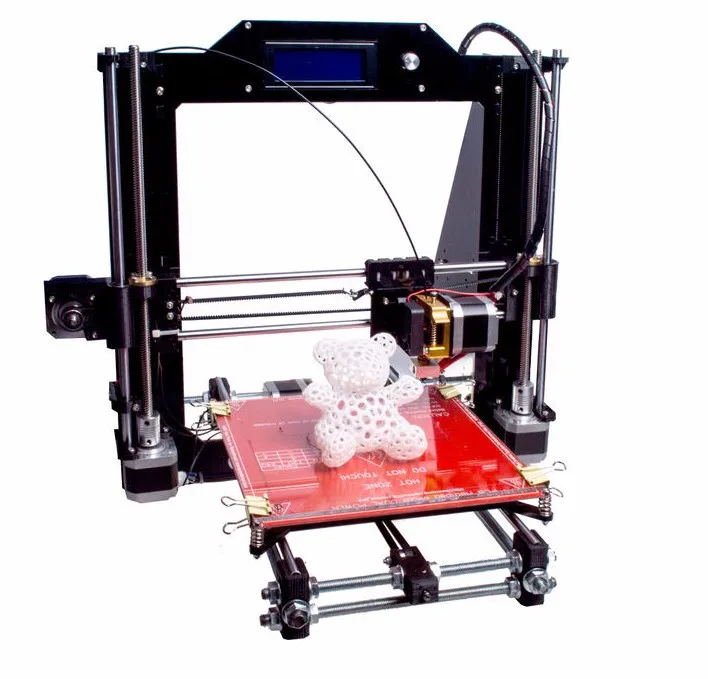
The time has come for experiments, what I have been going for so long and what I have been waiting for so long.
First experiment.
Place a small amount of silver into the boat fixed between the conductors. Above the boat I install a steam conduit - a soldered tin cylinder, which, as I thought, should limit the spread of metal through the chamber. Above the steam conduit there is a lid with a hole of 2 mm, behind the lid there is a target on which the metal should condense. It is a pity that there are no photos left, but the vacuum chamber was completely dusty. There was not a single place where there was no applied layer of metal. In the photo below, it’s not a different planet at all, but silver sprayed onto the inner surface of the wall. nine0003
Second experiment.
I thought it was because of the large gaps between the boat and the steam line. The solution was born immediately and quickly. I took two boats and combined them so that a shell was obtained. I placed silver inside, and cut a hole with a diameter of 2 mm in the upper half.
And he began to heat up the whole thing. But, I did not take into account the rigidity of the boats and the rigidity of the current leads. The shells parted a little and a gap formed between them, through which steam also flew in all directions. nine0003
As a result - spraying in the entire volume of the chamber. In the photo below there is a viewing window, the boat in which was slightly above half, but the window was completely dusty.
Third experiment.
After a little thought and grief, I thought that the container with the evaporated metal should be airtight and with only one outlet, but how and what to make it. From tungsten - very expensive and difficult to process. The way out has been found! Graphite is an excellent material for making a crucible, let's call it that. On the ad site, I found an ad for the sale of graphite bars from the contact whiskers of a trolleybus, cut out a bar with a hole in the center and made a cover for it.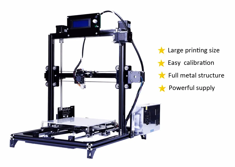 In the photo below - just a bar with a hole for the material (without a cover). nine0003
And in this photo already in the chamber with the lid installed (the hole in the lid is 1 mm in diameter).
Under the spoiler are a few photos with a short period of time, from which you can see how dusty the viewing window is.
Loss of transparency
It is obvious that in this case, too, there was no success, to my great regret. All three experiments were carried out with a gradual increase in temperature from the state when evaporation does not occur. nine0003
A small video in which the information is presented in a slightly different way, in a different form and volume.
Video link
www.youtube.com/watch?v=4yWQOWIG1qw
Unfortunately, it was not possible to get what was intended, but, on the other hand, invaluable experience was gained in the design and manufacture of vacuum equipment. Most of this experience I have shared with you and I would be very grateful if you express your opinion on this issue.
Thank you all and good luck.
Homemade Black Pill 3D printer (STM32F401CCU6)
Good afternoon.
I would like to tell you my thorny path in building a homemade 3D printer.
For a long time I dreamed of a 3D printer, but I could not decide whether to buy ready-made or build it myself.
It all started with an analysis of the models offered on Aliexpress. I understood that due to the increase in prices, it does not make sense to buy a ready-made version, since I will not use the printer often. After watching a "bunch" of videos about homemade 3D printers, I decided what kind of printer functionality I need. Most of the DIY was done with an Arduino Mega 2560 expansion board called RAMPS. There is nothing wrong with this solution as it is quick and easy. But I never liked the concept of a “sandwich”, and in consequence of the rise in price of the Arduino Mega, I decided to find another electronic basis for my homemade 3D printer.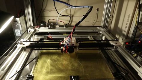 After reviewing a lot of offers, I realized that buying a board designed for 8 bits in 2021 is no longer relevant, and ready-made solutions for 16 and 32 bits are unreasonably expensive and most of the presented models have many functions that I will not use. Suddenly, I "stumble" on an article by a respected 3dmaniack with his solution and a board called RABPS. I'm redoing a project on short notice, but I'm running into an unforeseen problem. The RABPS board is based on the Blue Pill (STM32F103C8T6) microcontroller, but there are two versions of the microcontroller with 64kb and 128kb Flash memory. Naturally, our "friends from the Middle Kingdom", replacing labels, sell a cheaper option under the guise of an expensive one. As a result, firmware weighing more than 120 kb did not fit on the board. This failure did not stop me, but on the contrary, gave me an incentive to look for solutions. And continuing the search, I found a mini project by zooinginer, based on the same RABPS board, but based on the Black Pill microcontroller (STM32F401CCU6).
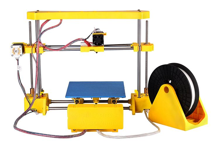 With minimal modifications in the form of a pair of jumpers and cut tracks, this microcontroller will function in this board. The big difference between STM32F401CCU6 and STM32F103C8T6 is that under this marking there is always a 256 KB Flash memory, which is enough for flashing. Well, that's all, I found the answer to all my requests and it remains only to design a printed circuit board and manufacture it. nine0003
Next, I will divide my path into 3 parts.
1) PCB manufacturing;
2) Firmware;
3) Housing and kinematics.
I would like to start my story about the thorny path of a homemade 3D printer.
So, in this part of the article, I will consider everything related to the board, from design to the finished solution.
As mentioned in the introduction, I took as a basis the project of the respected 3dmaniack with his solution and board called RABPS and the zooinginer's project with the adaptation of the RABPS board to Black Pill (STM32F401CCU6).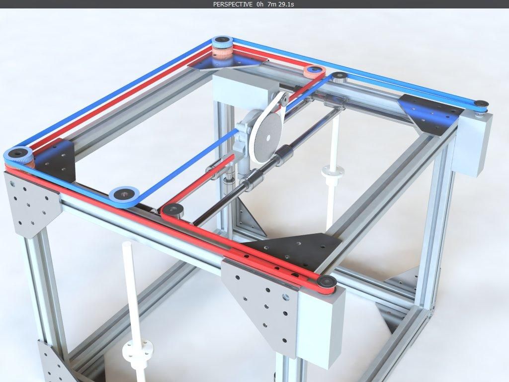 Having experience in the Sprint Layout program, a PCB design was created in a couple of evenings, but, as it happens, there were some mistakes. From a banal error in the size of the board components, which is quickly corrected, up to errors in the LUT technology. Looking ahead, I left him in the direction of the photoresist. nine0003
Let's get started.
We print photomasks, which will illuminate the photoresist. I printed on a laser printer and the toner density on the template was medium, which subsequently led to a poor result.
Violet streaks and dots are visible on the unexposed areas. This indicates that in these places the photoresist began to light up through the gaps in the template. This led to the fact that in the process of washing off the excess photoresist, the necessary tracks began to be washed off. The solution to this problem is simple: you should make graphite dust by rubbing the pencil tip on sandpaper, and gradually rub it into the template.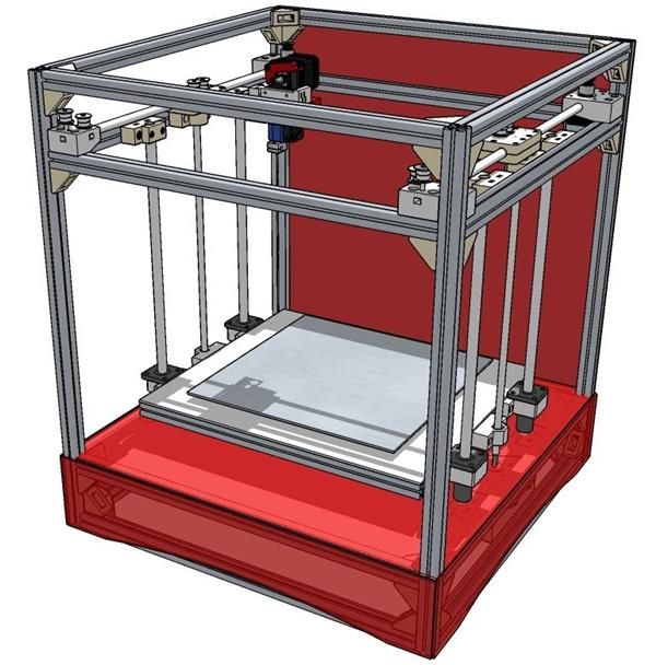 As a result, the template becomes more contrast and the problem is eliminated. Having corrected the defect in the template and obtained an excellent result, we wash off the unnecessary photoresist in a 3% solution of soda ash, and proceed to the etching process. I poison in a solution of peroxide and citric acid. The process is not fast. Although when the solution is heated, it goes faster. After etching, we remove the remnants of the photoresist from the tracks by soaking the board in the same 3% soda ash solution overnight, and enjoy the good result. nine0003
Next comes the optional part, namely the solder mask coating of the board. There are many types of masks, I settled on a Dynamask 5000 film solder mask, bought at the Chip and Dip store. The application process is very simple. Gradually peeling off the protective film, we rub the mask to the board. Next, according to the template, we illuminate the mask, and after that, wash off the unexposed places in a 3% solution of soda ash, and send it to be tanned in the oven for one hour at a temperature of 100 degrees Celsius.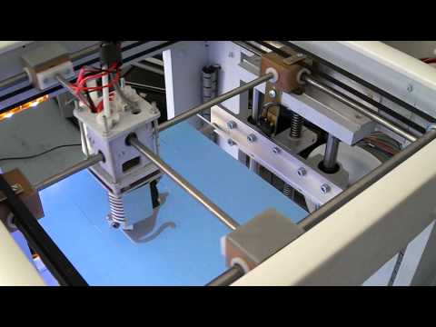 We receive. nine0003
Then we move on to soldering the components.
Since I don't have a device (mini-machine) for drilling boards, I use a conventional screwdriver. But because of its mass, at the slightest inclination, the drill often breaks. I tried to translate most of the components into smd execution, for example, voltage stabilizers, resistors and capacitors. All denominations are indicated in the scheme. The result is such beauty.
This is the second part of the story about a homemade 3D printer. nine0003
It's about the firmware, or rather about the problems that I encountered.
For me, this stage was the longest. First, I dealt with the Visual Studio Core program and its platformio ide add-on. Then there were “dancing with a tambourine”, due to the selection of the platformio ide version, since the firmware refused to assemble with some versions. I first put Visual Studio Core not on drive C, but on an additional one, because of this, the firmware also did not compile. It also took a lot of time that when you open the firmware you don’t need to immediately press build (first you need to wait 10-20 minutes for all libraries to be downloaded from the Internet). Dear zooinginer in his article described what needs to be done so that the firmware is compiled and installed on Black Pill. With a lot of torment, with the help of diman77, I still managed to compile and assemble the firmware, and then, using the Marlin setup video, I set the parameters for my configuration and for my self-made Smart_Controller. nine0003
Under the article I will leave all the necessary links. If you are interested in my homemade Smart_Controller, I can post a separate article on it.
This is the third part of the story about a homemade 3D printer.
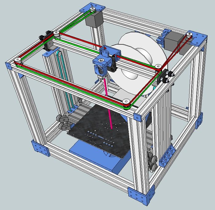
It's about choosing kinematics and bringing drawings to life.
There are many types of kinematics on the Internet, but for myself I singled out three: Prusa (“drygostok”), H-Bot and Ultimaker. I will briefly describe the pros and cons of these kinematics (in my opinion).
Prusa (“drygostol”)
Pros: ease of assembly, cost of components, easy access to the part.
Cons: open working chamber.
H-Bot
Pros: Precision print, closed oven .
Cons: stretching of the belt due to its large length.
Ultimaker
Pros: Printing accuracy, enclosed build chamber, use of short belts.
Cons: Dependence of the print quality on the quality of the guide rollers.
Since I don't need a printer for bulk printing, I settled on the kinematics of the "drygostok". There are many ready-made drawings on the Internet, but I wanted to make something of my own. For the course "Computer graphics" at the institute, I learned how to draw in AutoCAD. A frame drawing was created in 3-4 days. Next, I had a choice: to cut parts out of plywood with my own hands or contact a laser cutting company. I turned to professionals. The advantage of laser cutting is its accuracy and quality. Then I spent a couple of days to completely glue the frame of the 3d printer.