3D printer calibration software
3DOptimizer (Open Beta) - Intelligent 3D Printer Calibration
Table of Contents
Hear ye, hear ye! The future is in Open Beta
Bed-leveling to get that perfect first layer. Then, there are temperature towers, stringing tests, and bridging challenges. All so that we can get the best out of our 3D printers. The amount of wasted filament and time is enough to fill an entire recycling plant for a year, right!? I’ve often wondered, “There must be a faster, easier way.” Well, now there is! The team at FabControl have released 3DOptimizer (Open Beta).
Why 3DOptimizer was created
3DOptimizer is a unique software tool to tune the main FFF printing settings for open-materials printers. Said another way, it quickly helps you find the best Slicer values. FabControl states that,
“Finding the right printing settings is not easy. Two extreme situations exist at the moment. Either printer manufacturers offer users a black box with predefined printing settings and a limited number of printing materials (closed printers), or printer manufacturers leave the users alone with dozens of printing settings and materials (open-materials printers).
Due to the multifactorial of the printing process, one has to test many different combinations of slicing parameters. 3DOptimizer offers a way to make your testing process replicable and traceable by using a systematic testing framework. In 3DOptimizer, you can test up to 28 different parameter combinations in a single print, and, thus, determine the optimal printing settings much faster.”
I contacted one of the team members, Krišs Bērzkalns. He shared that it “started as an in-house tool at a 3D printer hardware manufacturer. Once the tool proved to be useful, it was decided to branch out as a separate company and develop the software further.”
How the Software Works
First, 3DOptimizer has you select a testing target; stronger, faster, or better. In other words, if you are looking for mechanical performance from your prints, choose strength. Instead, want shorter printing time without sacrificing success rate? Faster. Or how about the best appearance quality? Better. From there, the wizard sets up tests for as few as four core settings:
- First-layer track height vs first-layer printing speed
- Extrusion temperature vs printing speed
- Retraction distance
- Bridging extrusion multiplier vs bridging printing speed
As a result of the selected testing target, most values are pre-populated to match your goal. Next, the wizard generates g-code that creates a series of parameter combinations in the same print. Ergo, you can visually see the impact each setting makes. Then, you choose the best parameter combination; which is used in the next test. Once all tests are complete, a configuration file is generated for you to download and import into Slicer software. Currently, in Open Beta, 3DOptimizer supports Cura, Simplify3D, and PrusaSlicer. Here are images of my tests, which I used GST3D filament to run.
This slideshow requires JavaScript.
Key features
- Optimize printing settings for any material/printer combination
- No simulation – real-world tests, giving you settings that work for your exact machine
- Save time – total time for all 12 tests is approximately 4 hours
- Download tuned settings as Slicer configuration files
- Use a repeatable, logical approach
- Identify trends – instantly see how core changes affect printing results
- Save material – using a 0.
 4mm nozzle, all 12 test use only about 25m of filament
 - Share and distribute settings you combine
Don’t wait, act now before it’s too late!
Because 3DOptimizer is only in open-beta until end of March, sign up now! Until then, everyone is more than welcome to try it out and give feedback on how to improve it. While FabControl tests it extensively in-house, real-world feedback and real-life use cases will help improve it even faster. Krišs also shared that they are currently working on adding custom g-code beginnings and ends. This will allow for more customizing, like adding auto bed-levelling or presenting the finished print. Remember, the main goal is to eliminate the hours of guesswork usually associated with FFF/FDM process development.
If you want to learn more about the impact different Slicers have on your prints when using the same settings, read my article about the Artillery Genius.
3D3d printer3d printing3d printing processing3DOptimizerabsbetaCalibrationfdminov3dnewsnylonpetgpla 2020-03-22
Tags 3D 3d printer 3d printing 3d printing processing 3DOptimizer abs beta Calibration fdm inov3d news nylon petg pla
How To Calibrate A 3D Printer [Quick and Simple Guide]
Want to calibrate your 3D printer to achieve the best possible prints? Here's a quick guide that you can improve the quality of your 3D prints even more!
By Justin Evans
So you’ve bought yourself a brand new 3D printer and you can’t wait to get started. Trouble is, you can’t just jump right in. Before that, you’ll have to know how and why 3D printers are calibrated. That’s where we come in.
This guide will explain how you can calibrate your 3D printer. We’ll also be covering a little of the science behind it all, but we’ll try to keep things as easily understandable as possible so don’t worry. Now, let’s start by addressing the common question: “why do we need to calibrate at all?”.
Table of ContentsShow
What Is Calibration For?
Imagine you’re a baker. You’ve finally created a recipe that makes perfect bread each and every time. Congratulations! But fans keep writing to you telling you the recipe doesn’t work. After a while, you realize it’s because they’re all using the wrong size of baking tin. So how could this have been avoided?
Calibration allows 3D printers to avoid scenarios like this. Essentially, calibration helps ensure every print comes out exactly the same, regardless of the equipment used to create it. Nothing lopsided will be printed (unless that’s your intention), and your creations will be identical every time.
Preparing For Calibration
3D printers are very complex machines, and as such, calibration isn’t a one-click kind of task. We’d recommend setting aside at least half an hour to allow you to really get to the bottom of any issues that might occur.
You should also note that all printers are calibrated differently. Some have physical adjustment levers while others are controlled entirely via software. As such, the advice we’ll be giving should be used as a general guideline and not taken as concrete instructions.
Now, there are three main areas of your printer that require calibration: the extruder, the base plate, and the various motors. Below, we’ll explain how to attend to each of these parts.
How To Calibrate The Extruder
There are two main problems the extruder (the part that spits out hot filament) can have. The first is over-extrusion, where too much filament is used, and the second is under-extrusion, where too little is.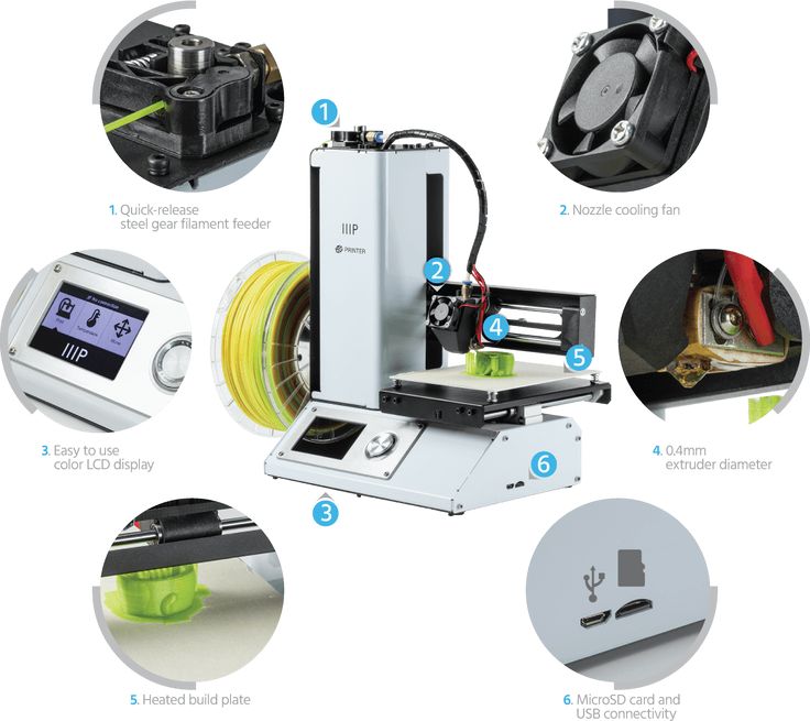 You should also consider the filament thickness, but this is easy enough to correct if it’s wrong.
To see if your printer is over or under-extruding, you’ll need a ruler, measuring tape, or set of calipers. Make two marks on the filament 100mm apart and align the bottom mark with the top of the extruder. Next, in your software, set the extrude length value to “100” and tell it to extrude.
If everything has worked as intended, the top mark will now be aligned perfectly with the top of the extruder. If not, you’ve got some work to do. You’ll have to adjust the extrusion (sometimes called “Flow”) percentage until the top mark aligns correctly.
How To Calibrate The X, Y, and Z Motors
Okay, the next step is to make sure your printer has its measurements right. To do this, use a piece of tape to mark two areas that are 100mm apart on the base plate. Position the nozzle over one, tell the printer to move 100mm in the correct direction and see if it ends up exactly over the tape.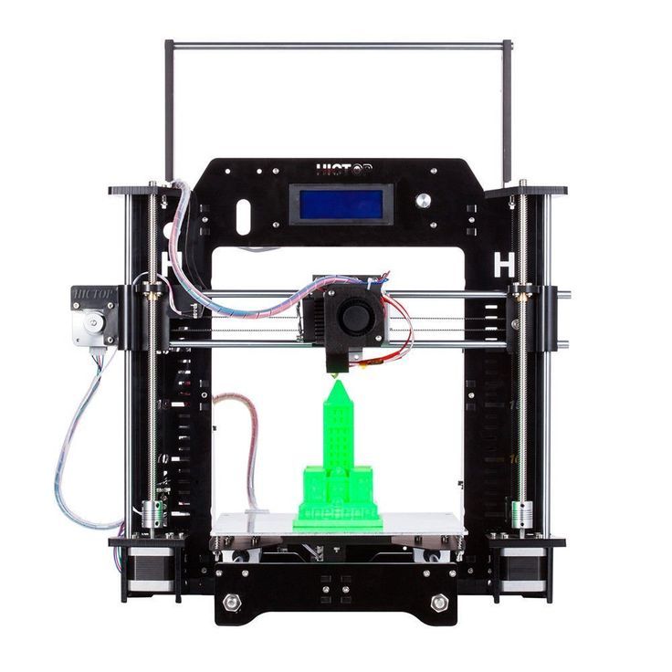
You should note that it’s likely not going to be ideal on the first try. 100.01mm isn’t the same as exactly 100mm, but these small differences can have large repercussions later on so it’s best to address them now. Adjust the M92 values for both the X and Y axes until it works perfectly.
For the Z motor, you’re going to want to use a ruler. Stand it vertically on the print bed and move the Z axis by 100mm. After this point, the process is the same: just change the M92 values until it moves exactly 100mm each time.
How To Calibrate The Base Plate
If you’ve noticed that your layers are too thin or that filament is gathered around the nozzle, you’ll likely want to level your base plate. This is so you can ensure the nozzle is the same distance from the base at all times. So how do you do this?
Start by centering the print head. You’ll likely have been provided with an index card, so place this between the print head and the base plate. By editing the Z-axis end stop variable, you can fine-tune the head’s distance from the base.
Most printers will have screws you can turn at each corner. Adjust these until you feel a slight resistance when you try to move the index card – you should still be able to move the card, but not freely. When you achieve this, you’re done!
Conclusion
3D printers can be difficult to get the hang of as there are dozens of options to tinker with at first. That said, there are only a few steps to take whenever you make a change. We’ve addressed these above and now, hopefully, you’re ready to start printing. Good luck and most importantly, have fun.
How Does Part Orientation Affect 3D Printing?
3D printer calibration utility
Good afternoon.
I would like to present you a small utility for calibrating 3D printers.
I originally wrote it for myself, but now I decided to post it for public access, maybe it will be useful to someone.
The program is free, but if anyone wants to thank the author, there is a special button :)
First, what this utility can do.
1. Automatic formation of a temperature column. You set only the temperature of the initial, final, step. The program itself substitutes these values into the column.
2. Bar feed calibration. The program itself calculates the required coefficients and saves them in the EEPROM of the board.
3. Table calibration, with automatic zero recalculation and saving in EEPROM.
4. Plastic consumption calculator - mutual conversion of plastic in terms of length, diameter, density and weight.
5. Well, the program has a terminal for manually sending commands to the printer.
The operation of the program directly related to communication with the printer was tested on the Marlin-1.1.x firmware.
Work on other firmware is possible, but not guaranteed.
How it all works below in this post.
Let's start with the temperature column.
As you know, different plastics have different optimum operating temperatures. To search for them, different methods are used, including printing temperature columns - hollow models in vase mode, with temperature changes, for example, every 10 mm. Then the resulting column is studied visually for defects, bubbles and mechanically for destruction, as a result of which the optimal temperature for using this particular plastic instance is determined.
Usually such pillars are formed by hand by editing the finished G code by inserting commands to change the nozzle temperature at certain intervals.
The work is not complicated, but it can be automated, which this utility successfully copes with:
On the tab /Plastic temperature/ there are three fields in the upper left where you enter the initial temperature for the test, the final temperature and the temperature change step.
By pressing the /Process file/ button, you select a temperature column at least 10 cm long, sliced in the vase mode. For convenience, I prepared such a column, you can open it with the /Open STL/ button and peel it off.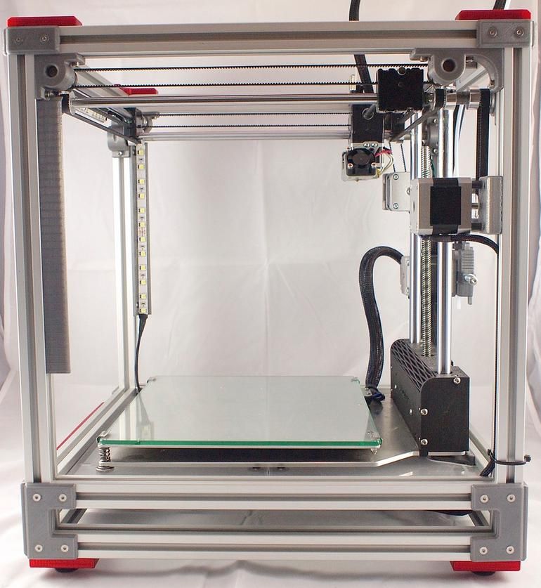
After processing, a file will be generated with the name: FileName_(TempStart-TempEnd-Step).gcode.
Example:
Temperature column_(260-190-10).gcode.
It will contain the temperature change every 10 mm with the specified step and range, in addition, it will be cut according to the specified range, it remains only to print it.
Bar feed calibration.
A common task, especially for beginners. This utility allows you to automate this process.
On the /Bar Feed/ tab, press the /Pass plastic/ button, having previously connected to the printer (the /Connect/ button on the right) and warming up the nozzle. After feeding, you need to measure how much the bar actually stretched, insert this value in the field next to the /Really stretched/ button, press it. The program itself will recalculate the feed rate, send a command to change this rate to the printer. You can repeat this operation again to make sure that everything is fine, or you can immediately save this coefficient in EEPROM by pressing the appropriate button.![]()
Table calibration.
This task also causes some stupor in beginners, the program is designed to ease it somewhat. Everything you need is collected on the tab /Calibration of the table/:
Calibration means finding the zero offset of the table and saving it in the EEPROM of the board. Leveling the table with bolts is not included in the program function!
Of course, here you also need to connect to the printer first.
Next, the sequence of actions is as follows.
1. Presses the /Home/ button.
2. Select the step with which we will move the Z axis.
3. Use the arrows on the keyboard to shift the nozzle and the table to a distance that we consider to be the zero of the table.
4. Press the button /This is zero/.
5. Check if necessary.
6. Save to EEPROM.
Plastic calculation.
On the corresponding tab there is a calculator for the mutual conversion of plastic in terms of length, diameter, density and weight. Enter the known values and click the /Calculate/ button next to the field whose value you want to calculate.
Printer connection.
Everything here is about the same as in all other printer management programs.
Select the COM port, speed, press the /Connect/ button, the history of data exchange with the printer will appear in the large window: This field saves the history of commands and they can be re-selected by clicking the triangle on the right side of this field.
General.
Settings in the program, including text in large text fields, in which you can write any comments yourself, are saved automatically when you close the program, or by pressing the button at the bottom, in the center of the program window.
There is also a red button next to it, which you can use if the program turned out to be useful to you :)
This button is for quickly transferring any amount from a card, mobile phone account, Yandex Money account.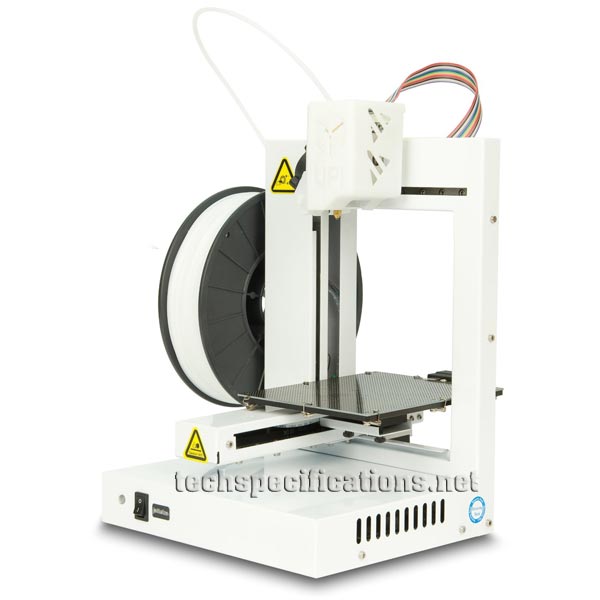
The transfer is carried out on the Yandex Money website, so your payment data will be protected by this system.
Link to the utility archive.
3DPrinterTool.zip The program does not require installation, just unpack the archive.
3D Printer Calibration / Sudo Null IT News
Sometimes the owner of a 3D printer has to do this. I will tell the habr-community about my method. Please note that the manual is detailed, but leads to excellent results - the model adheres perfectly and does not peel off during the printing process.
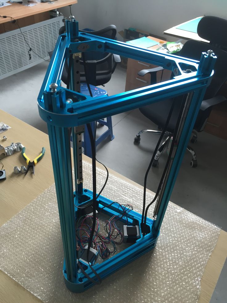
To begin with, I would like to note that I honed my skills on the SmartCore Aluminum printer purchased here.
Installing the heating platform
The heating (or non-heating, depending on the printer) platform must first be set in height. To do this, there is a limit switch for the Z axis.
From Wikipedia:
A limit switch is an electrical device used in control systems as a sensor that generates a signal when a certain event occurs, usually mechanical contact of a pair of moving mechanisms.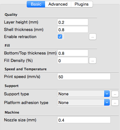
This trailer can be adjusted in height by means of a tightening bolt and clamping bolt.
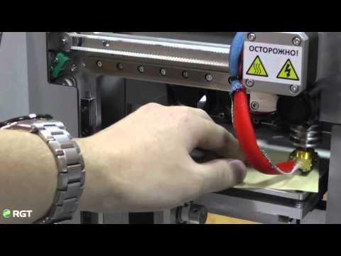
It is necessary to set it so that the surface of the platform clearly touches the extruder nozzle.
For further calibration, we will use Pronterface from the Printrun software package.
The advantage of this package is the visual and convenient control of the nozzle and the printer platform, but if someone is more comfortable using Repsnapper, it is also quite suitable. Cura is not suitable for calibration, for lack of the necessary functionality for this.
To continue, let's make sure that when you press the "Home" button (white house is shown), the platform rises and rests closely, but does not try to move further towards the nozzle.
Since the firmware on my printer was taken directly from the SmartCore Aluminum repository (albeit not directly from Marlin), the nozzle goes to the middle of the platform. If this is not the case for you, and the nozzle remains in the corner at zero coordinates, it's okay, this is not important for further calibration.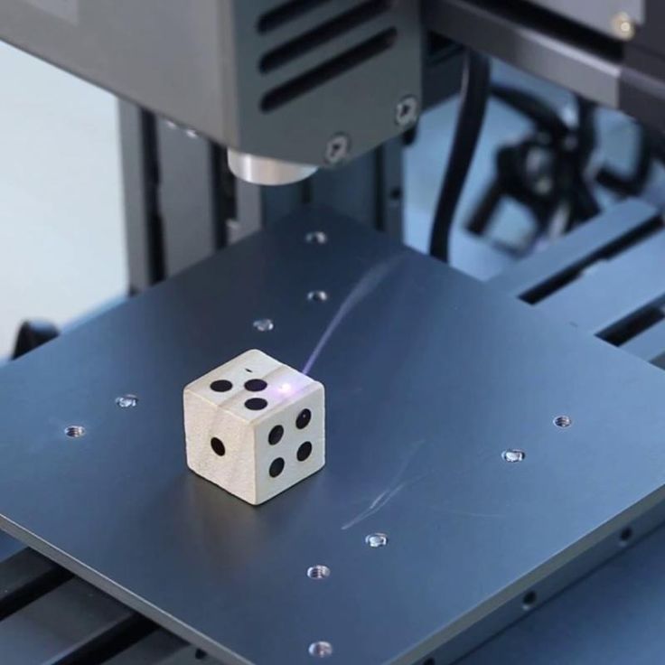
Calibration
The following steps must be carried out in turn on the center, corners and reference circle:
- Click on the Z-axis calibration
- If the corner rests against the nozzle (the center should rest, as we achieved by adjusting the height of the limit switch during preparation), then we slightly press the platform bolt at this corner until a minimum clearance appears.
- We eliminate the minimum clearance, but no more. Ideally, we should have a nozzle that is clearly butt in all corners and in the center when you click on the Z-axis calibration. This is the result we need to achieve for high-quality printing, more on monitoring the result later.
- Now you need to make sure that when you click on , a gap will appear. If this does not happen, you can slightly release the bolt that presses this corner and, by successively pressing the green house, then the “0.1” button, repeat until the desired result is obtained.

After we finished the calibration at all five points and went through them so that we didn't have to change anything, we can proceed to check the calibration result.
Test
For testing, I use a simple model drawn in FreeCAD and gcoded in Cura. Plastic, the more accurate the diameter, the better - I take it here because of the declared accuracy and variety of colors. However, for verification, we will use the natural color of ABS plastic.
The meaning of a simple little test model is probably clear - saving money and time.
It is in this sequence that it makes sense to check. However, if you are confident in your calibration, then you can immediately start with step 2. Well, if you already have experience and you are absolutely sure of your calibration, then you can immediately go to step 3 - print 5pad.gcode.
The difference is in the number and arrangement of products.
I will describe the verification of the first step, since the rest are similar.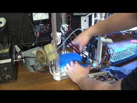
Suppose one side of the platform is too highly calibrated. It is very easy to find out as a result:
Top view:
And what is more important for us now is the bottom view:
- this is what the Cura rim looks like if the nozzle is located too high to the platform. Plastic does not fall accurately, sometimes clinging to neighboring lines.
Consider the opposite situation - if the nozzle is too pressed against the platform:
As you can see, not everything is smooth here either, the plastic, trying to fill the available space, will fit on adjacent lines, and on the next layer, the nozzle re-clings and smears again over the available space. However, it should be noted that in this case the model sticks very well, and the calibration defect is not visible on the next layers. Moreover, it may not even be noticeable at all if you choose a substrate in Cura for sticking the model to the table.
Finally, the desired and correct result:
Here you see a slight burning, but it is associated with an uncleaned piece of thread, which is clearly visible in the photo of the bottom view. Similar burns are rather inherent in the previous case, when the nozzle is too pressed. And the rest - smooth lines, tightly laid. That's the way it should be. Congratulations - the center point calibration is successful.
It is normal if such a result is obtained on glass at a temperature of 100 degrees. At the same time, if the glass is degreased and even, then after the end of the calibration, it will not come off during the printing process. You can try peeling the part off the heated bed after printing. Until it cools down to 90-80 degrees, you might not even be able to do it without damaging the glass. Also, the absence of a draft may be important, which affects the equally important uniformity of heating of the platform surface.
Here are general photos for easy comparison:
Top view:
Bottom view:
Further verification is similar in essence, but 4pad.gcode should be printed - covers a slightly larger central area. And 5pad.gcode - will show the quality of the calibration in the corners.