3D printer banding
5 Ways How to Fix Z Banding/Ribbing – Ender 3 & More – 3D Printerly
Most 3D printer users have experienced Z banding or ribbing issues at some point in their 3D printing journey, same with me. I wondered though, how do we fix this Z banding issue, and are there simple fixes out there?
The best way to fix Z banding in your 3D printer is to replace your Z-axis rod if it is not straight, enable consistent bed temperature with PID, and use layer heights which avoid your 3D printer using microstepping. A faulty stepper motor might also cause Z banding, so identify the main cause and act accordingly.
These fixes are fairly easy to do but keep on reading for more key information. I’ll give you a detailed description on how to do them, as well as what to look out for and other tips to fix Z banding issues.
If you are interested in seeing some of the best tools and accessories for your 3D printers, you can find them easily by clicking here.
What is Z Banding in 3D Printing?
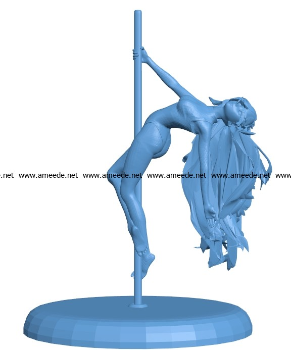
Many issues in 3D printing are aptly named after what they look like, and banding is no different! Z banding is a phenomenon of bad 3D print quality, which takes on the visual of a series of horizontal bands along a printed object.
It’s pretty easy to figure out whether you have banding just by looking at your print, some being a lot worse than others. When you look at the image below you can clearly see the thick lines with dents which look like actual bands on the print.
In some cases, it can look like a cool effect in some prints, but most of the time we don’t want Z banding in our objects. Not only does it look rigid and imprecise, but it also causes our prints to have a weak structure, among other downsides.
We can determine that banding is not an ideal thing to be happening, so let’s look into what causes banding in the first place. Knowing the causes will help us determine the best ways to fix it and prevent it happening in the future.
What Causes Z Banding in Your Prints?
When a 3D printer user experiences Z banding, it’s usually down to a few main issues:
- Bad alignment in the Z axis
- Microstepping in stepper motor
- Printer bed temperature fluctuations
- Unstable Z axis rods
The next section will go through each of these issues and try to help with fix the causes with a few solutions.
How Do You Fix Z Banding?
You might have tried several things to fix Z banding, but they just aren’t working. Or you have recently discovered it and searched for a solution. Which ever reason you came here for, this section will hopefully give you the guidance to fix Z banding once and for all.
The best way to fix Z banding is to:
- Correctly align the Z axis
- Use half or full step layer heights
- Enable a consistent bed temperature
- Stabilize Z axis rods
- Stabilize bearings and rails in other axes/print bed
The first thing you should look at is whether the banding is uniform or offsetting.
Depending on the exact cause, there will be different solutions that you should try first.
For example, if the main cause is from a 3D printer wobble or uneven movement from the rods, your banding will look at certain way.
The banding here would be where each layer slightly shifts in a certain direction. If you have Z banding which mostly comes out on just one side, it means the layer should be offset/depressed on the opposite side.
When the cause of your Z banding is to do with layer heights or temperature, you are more likely to get a banding which is uniform and equal throughout.
In this case, layers are wider in all directions compared to another layer.
1. Correctly Align the Z Axis
The video above shows a case of a poor Z-carriage bracket that holds the brass nut.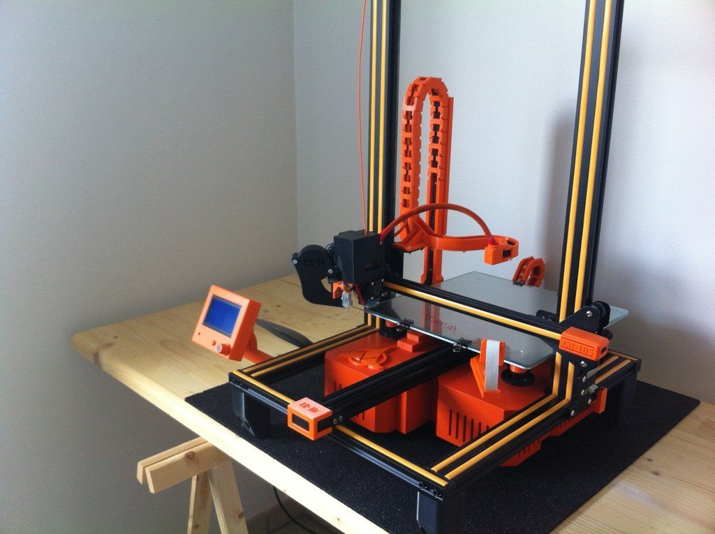 If this bracket is badly manufactured, it might not be as square as you need it to be, resulting in Z banding.
Also, the screws of the brass nut shouldn’t be fully tightened.
Printing yourself an Ender 3 Adjustable Z Stepper Mount from Thingiverse can help out a lot. If you have a different printer, you can search around for your specific printer’s stepper mount.
A flexible coupler also works well to get your alignment in order, to hopefully eliminate the Z banding you have been experiencing. If you are after some high quality flexible couplers, you’ll want to go with the YOTINO 5 Pcs Flexible Couplings 5mm to 8mm.
These fit a wide range of 3D printers from Creality CR-10 to Makerbots to Prusa i3s. These are made of aluminum alloy with great craftsmanship and quality to eliminate the stress between your motor and the drive parts.
2. Use Half or Full Step Layer Heights
If you choose the incorrect layer heights, relative to your 3D printer’s Z axis, it can cause banding.
It is more likely to show up when you are printing with smaller layers since the error is more pronounced and thin layers should result in pretty smooth surfaces.
Having some incorrect microstepping values can make it harder to fix this issue, but luckily there is an easy way to get around this.
When you compare the movement precision of the motors we use, they move in ‘steps’ and rotations. These rotations have specific values of how much they move, so a full step or half step moves a certain number of millimeters.
If we want to move at even smaller and more precise values, the stepper motor has to use microstepping. The downside of microstepping though, is the movements aren’t as precise as we want them to be.
It is easy to avoid your extruder having to use microstepping by using either the full or half-step values for your 3D printer, relating to layer heights.
I did a recent post which has a section about microstepping/layer heights and its ability to give you better quality prints.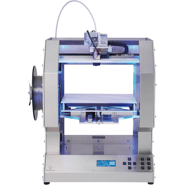
Basically, with an Ender 3 Pro 3D printer or Ender 3 V2 for example, you have a full step value of 0.04mm. How you use this value is by only printing in layer heights that are divisible by 0.04, so 0.2mm, 0.16mm, 0.12mm and so on. These are known as ‘magic numbers’.
These full step layer height values mean you don’t have to kick into microstepping, which can give you uneven movement throughout the Z axis. You can input these specific layer heights into your slicer, whether using something like Cura or PrusaSlicer.
3. Enable a Consistent Bed Temperature
A fluctuating bed temperature can cause Z banding. Try printing on tape or with adhesives and no heated bed to see if you still experience Z banding on your prints. If this solves the problem, then it’s probably an issue with temperature fluctuations.
Source | RepRapThe two types of bed heating processes are called Bang-Bang bed heating or PID bed heating. Bang-Bang bed heating is when your 3D printer reaches the set bed temperature and stops heating, which then causes it to cool down.
The bed then hits a certain point below the set bed temperature then kicks in again to hit the set temperature. Bang-Bang, referring to hitting each of those temperatures several times.
This can result in your heated bed expanding and contracting, at a level just high enough to cause print inconsistencies.
PID (Proportional, Integral, Differential terms) is a loop command feature in Marlin firmware to autotune and regulate bed temperatures to a specific range and stops wide temperature fluctuations.
This older video from Tom Sanladerer explains it pretty well.
Turn on PID and tune it up. There can be confusion when using the M303 command when identifying the extruder heater versus the bed heater.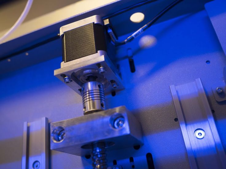 PID can keep a good, consistent temperature of your bed throughout a print.
The heating cycles of the bed fully turn on, then cool down before starting back up again to reach your overall set bed temperature. This is also known as bang-bang bed heating, which happens when PID isn’t defined.
In order to solve this, you need to adjust a few lines in Marlin firmware’s configuration.h:
#define PIDTEMPBED
// … Next section down …
//#define BED_LIMIT_SWITCHING
The following worked for an Anet A8:
M304 P97.1 I1.41 D800 ; Set the bed PID values
M500 ; Store to EEPROM
This isn’t on by default because some 3D printer designs don’t work well with the rapid switching that occurs. Make sure before doing this that your 3D printer has the capabilities to use PID. It’s automatically on for your hotend heater.
4. Stabilize Z Axis Rods
If the main shaft isn’t straight, it can cause a wobble which results in bad print quality. Bearing at the top of each threaded rod contributing to banding, so it can be a series of causes that add up to make banding as bad as it is.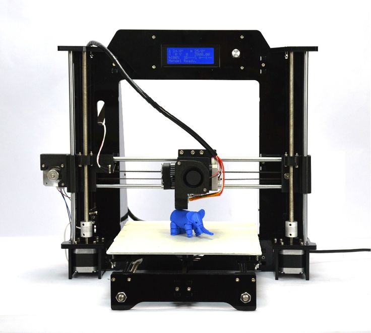
Once you identify and fix these causes of banding, you should be able to eliminate this negative quality from affecting your prints.
A bearing check on the Z rods is a good idea. There are rods out there straighter than others, but none of them would be perfectly straight.
When you look at how these rods are set up on your 3D printer, they have the potential to not be straight, which offsets the Z axis slightly.
If your 3D printer is clamped in bearings, it can be off-center since the hole where the rod fits through isn’t the perfect size, allowing for extra unnecessary movement side to side.
These side to side movements cause your layers to be misaligned which results in the Z banding that you are familiar with.
Caused by a poor alignment of the plastic bushings on the extruder carriage. This increases the presence of vibrations and uneven movements throughout the printing process.
For such a cause, you would want to replace the ineffective rails and linear bearings with hardened rails and high quality bearings.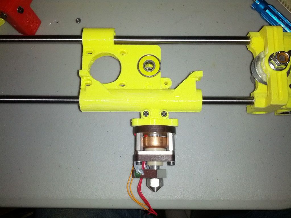 You might even want a metal extruder carriage if you have a plastic one.
If you have two threaded rods, try slightly rotating one of the rods by hand and see if they are both synced up.
If the Z nut is higher up on one side, try to slightly loosen each of the 4 screws. So, basically trying to get an equal angle on each side, so the movements aren’t unbalanced.
5. Stabilize Bearings & Rails in Other Axis/Print Bed
The bearings and rails in the Y axis can also contribute to Z banding so definitely check over these parts.
It’s a good idea to do a wiggle test. Grab your printer’s hotend and try wiggling it to see how much movement/give there is.
Most things will move a little bit, but you are directly looking for a large amount of looseness in the parts.
Also try the same test on your print bed and fix any looseness by shimming your bearings into better alignment.
For example, for the Lulzbot Taz 4/5 3D printer, this Anti Wobble Z Nut Mount aims to eliminate minor Z banding or wobble.
It doesn’t require a firmware update or anything, just a 3D printed part and a set of materials that attach to it (described on the Thingiverse page).
Depending on the design of your 3D printer, you might be more likely to experience Z banding. When the Z axis is secured with smooth rods, along with threaded rods which have bearings on one end that move it up and down, you won’t have this problem.
Many 3D printers will use the combination of a threaded rod connected to your Z stepper motor shafts to hold it in place through its internal fitting. If you have a printer with a platform carried by the Z axis, you can experience banding through wobble of the platform.
Other Solutions to Try Fix Z Banding in 3D Prints
- Try putting some corrugated cardboard underneath your heated bed
- Put the clips that hold your bed in place right at the edge
- Ensure that aren’t any drafts that affect your 3D printer
- Screw up any loose bolt and screws in your 3D printer
- Make sure your wheels can move freely enough
- Decouple your threaded rods from smooth rods
- Try a different brand of filament
- Try increasing the minimum time for a layer for cooling issues
- Grease your 3D printer for smoother movements
There are many solutions to try out, which is common in 3D printing but hopefully one of the main solutions works for you. If not, run down a list of checks and solutions to see if one of them works out for you!
Best Z Banding Test
The best test for Z Banding is the Z Wobble Test Piece model from Thingiverse. It’s a vertical cylinder that you can 3D print to see whether you are actually experiencing Z Banding or not.
One user realized that his Ender 5 had really bad horizontal lines, so he 3D printed this model and it came out bad.
After doing a series of fixes such as disassembling his Z axis, cleaning and lubing it, checking how it moves, and realigning the bearings and POM nuts, the model finally came out without the banding.
If you love great quality 3D prints, you’ll love the AMX3d Pro Grade 3D Printer Tool Kit from Amazon. It is a staple set of 3D printing tools that gives you everything you need to remove, clean & finish your 3D prints.
It gives you the ability to:
- Easily clean your 3D prints – 25-piece kit with 13 knife blades and 3 handles, long tweezers, needle nose pliers, and glue stick.
- Simply remove 3D prints – stop damaging your 3D prints by using one of the 3 specialized removal tools
- Perfectly finish your 3D prints – the 3-piece, 6-tool precision scraper/pick/knife blade combo can get into small crevices to get a great finish
- Become a 3D printing pro!
I hope this article helps you out. Happy Printing!
3D Printer Z Banding – Common Causes and Fixes! – 3dprintscape.com
No matter how well you set your printer up, it’s still highly likely that you’ll experience print defects from time to time. After months of use, screws can loosen and gantries can go out of alignment.
Z banding, or “ribbing”, is one of the least common issues you’ll encounter, but I noticed a few people asking about it. So I decided to write this article which goes through every possible cause of Z banding and how to fix it.
Some of the advice here applies to the Ender 3 but if you have a different printer, most of the information here will help you as well.
What Is Z Banding In 3D Printing?
Z Banding in 3D printing is a defect in the Z axis that causes print layers to protrude from the part. So the part ends up with obvious layer lines that ruin the appearance of the print. Z banding makes it impossible to print parts with a smooth finish. It’s a print defect found in FDM printers caused by multiple factors which I’ll cover shortly.
Z banding occurs when the printer doesn’t move straight up and down the Z axis during a print. This is caused mostly by lead screws or motor shafts that are bent. Loose screws are also a common cause of defects like Z banding.
What Does Z Banding Look Like?
Z banding looks like lines or ribs on a print where it should be smooth. Z banding is usually the appearance of a uniform pattern in print layers that stick out from the part. Sometimes, Z banding looks like a bulge around the part in only a few layers, with the rest of the model looking normal. Z banding results in a ribbed surface instead of a flat one.
Causes Of Z Banding In 3D Printers And How Fix It
There are a lot of reasons Z banding could occur. I’ll explain the most common causes and then go over how to resolve them.
Loose screws on the X axis gantry
Loose screws on the X gantry causes Z banding because both sides of the gantry don’t move together properly. This is a bigger problem with single Z axis screw printers compared to dual lead screw machines.
Solution: Tighten the screws that connect the X gantry to the Z rail on the left
Here are the steps on how to tighten the appropriate screws on an Ender 3, but it’s very similar for most FDM printers.
- Unplug the printer for safety reasons.
- Unscrew the four screws at the top of the Z gantry.
- Remove the Z gantry from the top of the printer.
- Manually raise the X gantry from the printer. (The extruder gantry)
- Tighten the screws on the left side of the gantry.
- Put the Z gantry back into the printer and tighten the top screws.
Screw rod coupler is skew
A skew coupler will cause Z banding because it puts the lead screw out of alignment.
Solution: Straighten and tighten the coupler on the lead screw
Unscrew the two screws on the coupler and remove it from the lead screw. Put a spacer of around 1cm at the bottom of the lead screw and then tighten the coupler back on. Remove the spacer after screwing the coupler on.
Once you’ve attached the coupler, print a Z motor spacer and attach it below the coupler to prevent Z binding.
Screws on X gantry are too tight
X gantry screws that are too tight cause binding on the Z axis. This is because the X gantry can’t move up and down the Z axis smoothly with over tightened screws.
Solution: Loosen the elliptical nut on the X axis gantry
If you have a 3D printer like the Ender 3, you might need to loosen the nut on the X axis gantry. If it’s too tight, it causes binding on the Z axis. To test if it’s tight enough, gently move the X gantry up and down with your hand. There should only be a couple of millimeters of play. It needs to be tight enough to reduce the play but also loose enough to allow the X gantry to move up and down with the Z axis accordingly.
After tightening, manually move the X gantry up and down the lead screw to make sure it’s not too tight.
The X gantry sags on the side without a lead screw
For printers that only have one lead screw, the X gantry can sag on that side. So the one side of the X axis will be a bit lower than the other.
Solution: Add an additional Z axis lead screw
Having the X axis gantry supported by a lead screw on one side only is problematic because it causes a bit of sagging on the side without a lead screw. This is especially bad if you plan to upgrade the hot end and therefore increase the weight for the gantry to support.
If tightening the screws doesn’t decrease the sag, rather upgrade your printer with an additional lead screw and stepper motor. This is also a good idea if there is no sag, but binding still occurs.
A dual lead screw upgrade will make your printer a lot more accurate and stable during prints, so you won’t only be fixing the Z banding, you’ll be increasing the printer’s overall performance.
Upgrade kits like these on Amazon will give your printer more accuracy and remove the play on the side that didn’t have a lead screw. This upgrade will also enable you to print at higher speeds with less wobble.
Filament not feeding through freely
Filament that’s not feeding freely into the extruder can cause Z banding because the filament pulls the extruder upwards and puts it out of alignment. Then the filament causes the X axis gantry to fall back into position when it manages to feed through again. This process repeats throughout the print, which causes the Z banding.
Solution 1: Add a filament guide
A filament guide will help the filament feed through the printer freely. It’s not a very complex part, so you should be able to print it even if you have some Z banding. Then you can print a good-looking one with the imperfect guide attached and swap them out.
Solution 2: Add a filament tube
Filament feed tubing also helps to feed the filament through in a uniform and controlled manner. There are a variety of tubes available like these ones on Amazon, so you can check which one suits your budget.
Bent lead screw
A bent lead screw is a major cause of Z banding because, as the screw turns, it moves the extruder in and out of the print incorrectly.
Solution: Replace the lead screw
Luckily, lead screws are widely available. You’ll need to check the dimensions of your lead screw to make sure you purchase the right size. To check if your lead screw is bent, remove it from the printer, place it on a flat surface and roll it over. It should roll smoothly across the surface and you’ll notice if it’s bent when it rolls with a wobble. Here are a few different lead screws on Amazon.
Bent stepper motor shaft
If the stepper motor shaft is bent, it will cause the Z axis to wobble constantly because it’s directly connected to the lead screw.
Solution: Replace the stepper motor
The best thing to do is replace the stepper motor if the shaft is bent. Here is a range of stepper motors on Amazon for you to look through. Just check the compatibility with your printer before making the purchase.
Loose stepper motor
A loose stepper motor will cause unwanted movement on the Z axis, especially with faster prints.
Solution: Tighten the stepper motor screws
Tighten the screws of the stepper motor just enough for it to have no movement when you move it with your hand. Don’t make it too tight or you’ll get a different variation of Z banding.
Dirty Z lead screw rods
Over time, the lead screws can gather dust, especially because it sticks to lubricants that should be on the screw. Dust is very abrasive and can cause the movement of the Z axis to be restricted. Dust can even damage the threading of the lead screw if you don’t clean it off from time to time.
Solution: Clean the lead screw
There are many ways to clean the lead screw, but I find the best way is with isopropyl alcohol because it strips any lubricant away, along with the dirt. I suggest pouring some of the cleaning agent into a small container and then dabbing a brush into it to brush off the dirt from the screw.
Remember to add lubricant again once you’re done cleaning the lead screw. I cover the full process in this video.
Inconsistent extrusion
Inconsistent extrusion can cause defects that look similar to Z banding. However, extruder feed problems usually create random ribbing and other defects on the part, whereas Z wobble or Z banding creates regular patterns of Z banding. If the ribbing on your print is random, inconsistent extrusion could be the cause. These are some ways you can fix it.
Solution 1: Clean the nozzle out
I only clean the nozzle out if it’s a more expensive one, like a hardened “high-quality” nozzle. Having said that, cleaning a nozzle is relatively simple. Here’s a video I made on how to do it.
Solution 2: Replace the nozzle
If you’re still using the stock nozzle and it’s clogged up, I suggest buying a higher-quality hardened nozzle like these ones on Amazon.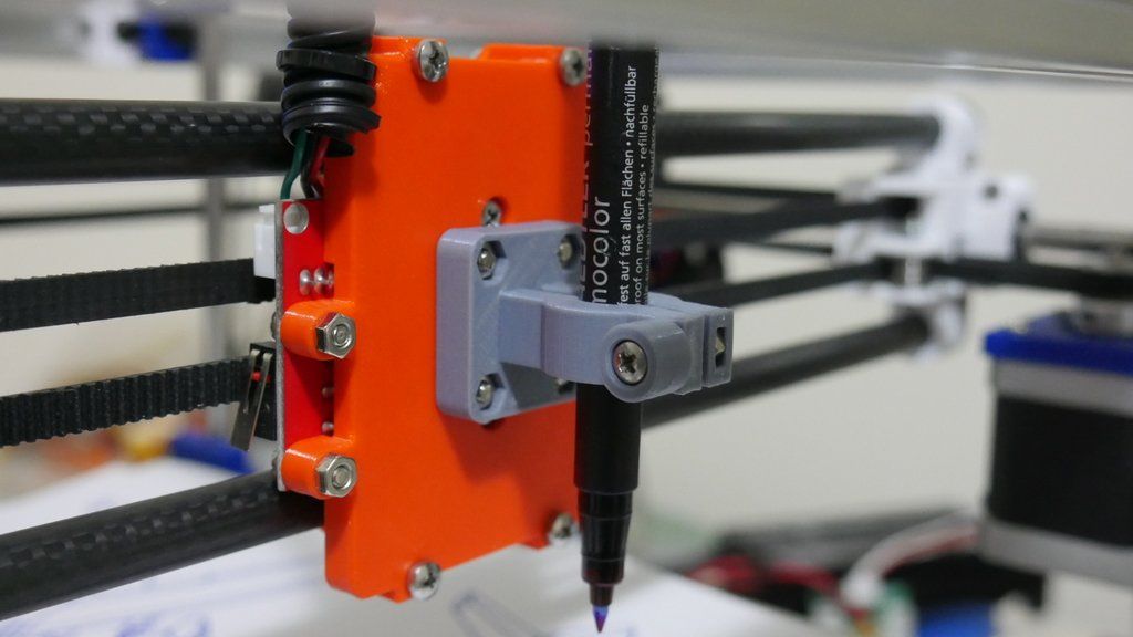 You’ll get better printing performance from them and they last a lot longer than weak stock nozzles. Here’s another video I made on how to install them.
Z Banding Test
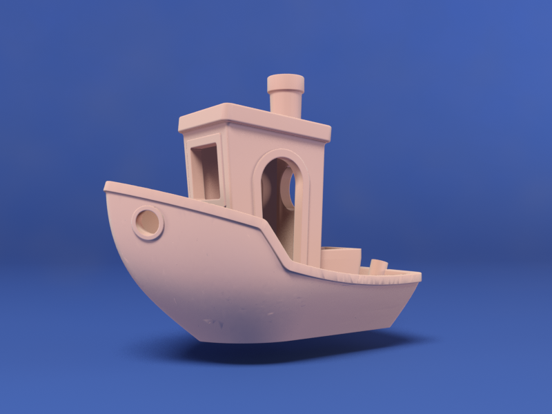
The best way to test for Z banding is to print a smooth surface cube. If you see Z banding patterns which look like fat print layers instead of a smooth surface, you have Z banding issues.
Here’s a detailed cube on thingiverse that you can print to test for Z banding on your printer.
How To Remove Z Banding Defects
To remove Z banding defects from a part, there are a few different things you can do.
Sanding
One of the easiest and most common ways of removing print defects is by sanding them away. Start with a low grit paper around 300 to 500 in the beginning and work your way to high grit paper like 2000 to finish the job off.
Wet the sandpaper before using it to polish the part. This will reduce heat generated by the friction of sanding and it gives the part an extra smooth finish.
If you’re polishing a flat area of the print, use a sanding block to prevent digging grooves into your part.
Try to sand the part in circular motions to avoid obvious sanding lines.
Related Articles
- Bed Leveling Issues – Common Causes and Fixes
- 3D Printer Speed VS Quality
- 3D Printer Nozzles (Detailed Overview)
- How Do You Resume A 3D Printer After Power Loss?
- Create a Temperature Tower Using Cura – The Easy Way
- Cura Profiles
Conclusion
Z banding in 3D printers almost always occurs due to misaligned parts in the printer. Parts become misaligned when screws come loose or if parts are bent. So it’s fair to say that you can eliminate the problem by tightening up the printer and making sure everything is in its optimal position.
Some cheap upgrades like spacers and filament guides can be very useful in eliminating Z banding. On the more expensive side, if you have a single Z axis screw rod, upgrading to a dual rod system will eliminate Z banding, increase accuracy, and speed capabilities of the printer in a big way.
Make sure you check out our YouTube channel, and if you would like any additional details or have any questions, please leave a comment below. If you liked this article and want to read others click here.
Industrial 3D printer for printing with engineering plastics CreatBot PEEK 300. Review 2020.
Contents:
- Creatbot Peek 300 general information
- Creatbot PEEK 300 Features and Package Contents
- Appearance and interface
- CreatBot PEEK 300 build chamber and print unit
- Mechanics and kinematics
- Electronics and electrical
- Slicer and print examples
- Output
Hello Friends! 3Dtool is with you!
Creatbot has firmly established itself in the market of professional FDM solutions and has a whole line of high-temperature 3D printers for working with engineering and refractory plastics. Starting with the junior model Creatbot F160 peek edition, ending with the giant Creatbot D600 PRO and Creatbot F1000.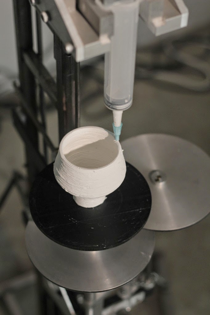 Now the lineup has been replenished with another new 3D printer CreatBot PEEK 300. It already follows from the name that this device is designed to work with engineering refractory materials and differs from its predecessors. Whether this is so, and how the printer architecture differs from other models of the line, we will try to determine in this review. Go!
General information about Creatbot Peek 300
Creatbot PEEK 300 is the manufacturer's application for the industrial FDM segment. This can be seen from several indirect and direct signs at once. Firstly, the kinematics removed from the active heating zone, secondly, thick two-layer walls of viewing windows, thirdly, a full-fledged system for heating the volume of the working chamber and, like a cherry on a cake, a water cooling system for the printing block.
Even compared to other models of the company, PEEK 300 looks more serious, which, in fact, the manufacturer himself claims.
Let's take a closer look at the device and consider it in detail
Creatbot PEEK 300 Specifications and Contents
Let's start with the classic features and equipment. The manufacturer declares the following characteristics of this model:
A rather large print area, a very impressive heating temperature of the extruder and table, the ability to “fire” materials like Polyether Efirketan directly in the chamber and a weight of almost 100 kilograms is another confirmation that we have a serious device.
Let's touch on a detailed analysis of the characteristics a little further. What is included in the package?
Absolutely standard set for CreatBot 3D printers, like the D600 Pro.
Also included is a woven carbon fiber adhesive platform already installed on the printer that can withstand very high temperatures. Similar to the one on the F430 Peek Edition.
Appearance and interface
Let's consider the 3D printer externally and get acquainted with the control interface.
Coated in signature gray powder paint, the Creatbot’s body looks quite powerful and at the same time concise. On the front panel we can see a viewing door, controls and a large blue company logo. On the right side, you can see the handles for transportation and the ventilation grille of the chamber.
On the right side are the same handles for transportation, the door of the coil compartment and the buttons for selecting the heating temperature of this compartment. You can dry the material at 40 or 60 degrees. The buttons are provided with pictograms. The same system is on Creatbot D600 Pro, for example.
There is another viewing window on top to facilitate access to the printing unit, loading plastic and other operations. In total, the camera can be accessed from two directions, from above and from the front, for most cases this is enough.
The front door has an impressive thickness, this is done to reduce heat loss during printing, the same thermally insulated doors were, for example, in the Total Z450, a similar industrial 3D printer, which we reviewed earlier.
Glass is also used double, to create an air temperature barrier. Material - apparently plexiglass on the outside and natural glass inside. The layers are laid with special bushings - white.
Estimate the thickness of the “nut” of the working chamber, the body of Creatbot PEEK 300 more like an armored tank than just a 3D printer.
On the right side of the front panel there is a Creatbot branded touch display with a USB connector and an indicator, as well as a temperature controller for the blower heaters of the DAC system.
Below is the model marking, emergency shutdown button and power button.
Go to the display interface.
Since all Creatbots have a single platform, their control interface is also approximately the same, so when the device is connected to the network, we are greeted by the already familiar blue touch screen interface with quite familiar icons, but still a little, there are changes.
In addition to the temperature icons at the top right, in the main window you can see the buttons for quickly turning on the preheat (Preheat), the filament change menu (Filament), the memory card menu (USB), the menu for moving along the axes (Move) and advanced settings (Settings).
Here we are offered to adjust the movement parameters (accelerations and jerks), change the temperature of automatic preheating, adjust the speed of the fans blowing the model, or perform auto-calibration of the platform.
Here you can reset the settings to the factory settings.
The axis movement menu contains axes familiar to the eye with a choice of movement step, buttons for positioning the head in the "Home" state for different axes and displaying the current coordinates.
The memory card window has not changed either. Here, everything is also divided into subfolders, but the display does not display the Cyrillic alphabet, alas. Use English titles.
The filament menu allows you to select a gentle extruder and, similar to the motion menu, load or unload material. The temperature is set during the process.
CreatBot PEEK 300 build chamber and print unit
Creatbot Peek-300 has a rather impressive volume of the working chamber - 300x300x400 mm. At the same time, according to the assurances of the manufacturers, most of it can be used for almost all refractory materials.
PEEK 300 has one of the "hottest" heating tables. The system allows you to reach 200 degrees on the surface. This is enough to print with any available refractory material.
The table rests on a thick base, the silicone is laid with a heater, the glass is fixed on the clamps.
There is LED lighting on the front. As you can see, the straps do not intersect, we have a classic H-Bot.
Media is fed from the spool slot on the left side of the machine. Here we see a heating module for drying the material, brackets for attaching two coils and a thread presence sensor.
At the top of the compartment is a temperature sensor.
A HEPA filter and a ventilation grille are installed in the right wall of the working chamber.
Lining the surface of the filter with activated carbon additionally purifies the air from harmful impurities.
Printing unit
Of course, the most interesting node of this device is the printing unit, because it has water cooling and a cunning hot blowing nozzle system. In the rear compartment of the printer there is a reservoir with water, a pump and a cooling radiator, through which the liquid heated in the printing unit is removed and cooled. The compressor and heater for the hot air system (DAC system) are also located there. The performance of such a water-cooling solution is much higher than with conventional air-cooling, and given the maximum heating of the nozzle up to 500 degrees, the system must be productive.
The print unit is also equipped with the unique and exclusive Direct Annealing System. Near it is an air duct, the air flow temperature of which can reach up to 120 degrees Celsius. This allows materials such as PEEK and PEI to be pre-fired, and thanks to the same high chamber temperature, the final polymerization process can occur much faster than with the classic method.
Printing unit - top view.
View - from below and the BlTouch table level sensor.
The print unit is equipped with two feed mechanisms and two hot ends, the extruders are motorized (as in Raise3D 3D printers). The rise/lowering of the hot ends is due to the torsion of the screw gear. The inactive nozzle rises during printing, and then lowers when they need to print (and so alternately each of the nozzles) the rise / fall occurs automatically using the electronics of the device. The BL Touch table calibration sensor is installed on the back wall, as on other professional Creatbot models.
Creatbot allows you to use nozzles with a diameter of 0.3 to 1.0 mm, brass or steel. But if the printer works with refractory and abrasive materials, it is preferable to use a steel nozzle.
The extruder tubes are all-metal, they correspond to their high-temperature counterparts on the D600 Pro models, except that they cool better and withstand heating up to 500 degrees, unlike 420 for the D600 Pro.
Mechanics and kinematics
Unlike predecessors Creatbot PEEK 300 has H-Bot kinematics, the belts are separated by height, classic steppers act as a drive.
The X-axis carriages are milled, metal, thick Hiwin rails and a 10 mm steel cord belt, the kinematics are perfectly implemented and finally built on a modern kinematic scheme. The blue substance in the photo is shipping lubricant.
The belts extend beyond the chamber, all delicate electronics, except for the control of the printing unit, are placed outside the chamber.
The Z-axis, as expected, moves with the help of a fixed ball screw along two 16-mm guides. There is nothing new here, we have seen a similar scheme on past models of the manufacturer.
The steppers themselves are hidden behind the back wall and are located in the electronics compartment. Paired - along the X / Y axes and Z stepper motors with a belt drive. Pay attention to the format of the motors, these are far from the classic Nema 17. In an industrial 3D printer, everything should be done in an adult way. It would be interesting to see a modification of the Peek-300 using servos like the D600 Pro.
Electronics and electrical
Let's move to the holy of holies of any 3D printer - the electronics compartment, in the CreatBot PEEK 300 it should be quite interesting.
And there is. The compartment stretched over the entire body of the device is packed with knots and elements to the eyeballs. Let's try to figure out what's what.
First of all, a powerful 14.6 ampere power supply catches the eye, which powers all the kinematics, the motherboard and other low-current piping of the device.
To the left of it are the electronics compartment cooling fans and a backup battery in case of a power outage, here we see a 220 relay in the amount of 4 pieces serving the printer's heating elements. There are 5 such relays in total. Separately for the table, printing unit and heating elements.
On the right you can see the heating element of the chamber volume, please note that the entire chamber is glued with thermal insulation from the inside, it is clearly visible from the electronics compartment. Heat loss with this approach should be reduced to zero.
On the left side you can see the elements of the water cooling system of the printing unit, which we talked about earlier.
Above is a reservoir with liquid with tubes connected.
As well as a radiator with a fan for active cooling.
At the very bottom is the pump and heater of the DAS system, which supplies hot air to the nozzle.
In the center of the compartment is the proprietary Creatbot motherboard, familiar to us from other company printers. Proven, reliable solution.
Quiet drivers with the ability to replace, a huge number of functions and high-quality factory industrial assembly. We hope the company will continue to practice this approach to production.
By the way, as befits such a device, Creatbot uses two power lines. Power - for heating elements and low-current for controlling kinematics and low-current piping. Also, without fail, the device must have access to grounding.
Slicer and print examples
Creatbot PEEK 300 can work with any open slicer on the market. Be it Cura, Kisslicer or Simplify 3D. However, the manufacturer recommends using its own solution - CreatWare, based on one of the old Cura builds. We considered this slicer in detail in one of our previous reviews on Creatbot printers.
As a test, let's print a product made of Ultran, this is a rather capricious material, and we just have a coil dried for another review.
Let's omit the slicer setting, we will only make a reservation that Ultran is printed at a temperature of at least 300 degrees on the extruder and 120 on the table.
Let's choose a layer thickness of 0.2 mm.
As a result, we get such a beautiful spiral made of durable material, without the use of supports, in excellent quality.
For better sintering, we set the temperature in the chamber to 70 degrees, as you can see, this is quite enough for printing with carbon-filled polyamide.
By the way, we printed the same impeller from FormaX, you can see the printing process and the result in the video review of this 3D printer on our Youtube channel. The details are very similar. Both externally and on quality of the press.
Output
CreatBot PEEK 300 a logical continuation of the manufacturer's industrial line of devices.
By correcting and improving the design, the company provides the possibility and quality of printing with refractory engineering materials 3 times cheaper than solutions from well-known manufacturers Stratasys and Funmat, while not worse.
Print control systems, electronics removed from the heating zone, professional and modern kinematics, a well-thought-out system for drying and feeding plastic, reliable and well-proven electronics, a motorized double printing unit with the function of firing a part, these are unconditional trump cards in favor of CreatBot PEEK 300.
By expanding and refining the experience gained in the development and implementation of the D600 Pro, the company has created a truly worthy solution that fully corresponds to the tasks assigned to it.
Creatbot declares full support for the most common refractory engineering materials, and judging by our test, the printer can really print with them with high quality.
Who is the Peek-300 for?
This is clearly not a homemade solution. Large size, huge current consumption, such, without exaggeration, a large organization, a manufacturing company, a research institute or a laboratory can afford such a machine.
Such a device will perform well in R&D chains, where you need to quickly get a running prototype or final functional part and immediately introduce it into production.
This 3D printer will perfectly cope with the task of manufacturing rare and loaded spare parts of other machines or mechanisms.
It will also perfectly fit into the scheme of modernization and optimization of existing production, or will become the basis for a new one.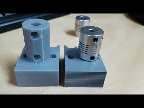
Well, that's all we have! See you soon!
You can purchase the Creatbot PEEK-300 3D printer from our company. We are the official distributor of the manufacturer's plant for the sale and service of CreatBot3D equipment in the Russian Federation.
To place an order, or contact us for other questions, you can:
-
By email: [email protected]
-
Phone: 8(800)775-86-69
-
Or on our website: https://3dtool.ru
Don't forget to subscribe to our YouTube channel:
Join our groups in social networks:
In contact with
Equipment for 3D printing in Kulebaki
- Main
- Sale
- Machining centers and CNC machines
- 3D printing equipment
You can quickly compare the prices of 3D printing equipment and choose the best options
Equipment For the construction of energy efficient houses
Condition: Used Year: 2014
Great solution for small businesses.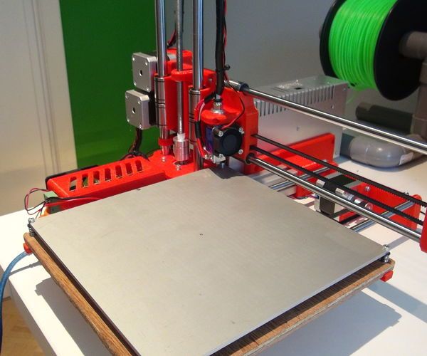 The equipment produces from 100 m2 of formwork per shift (this is an average of one floor of a house with 100 m2 of flooring, this is the simplest set for fixed formwork and the most...
06/16/2019 Kulebaki (Russia)
450,000
PVC window equipment
Condition: Used Year of issue: 2012 Manufacturer: KABAN (Turkey)
I sell a line for the production of PVC windows, well-established and equipped with everything necessary for a quick start. The machines were used in a gentle mode and were in the same hands. one. KABAN AD...
16.06.2019 Kulebaki (Russia)
PVC window painting equipment
Condition: Used Year: 2017 Manufacturer: FEYCO (Switzerland)
We invite you to consider expanding the provision of services in the window market and increase the profits of your business by introducing painting production.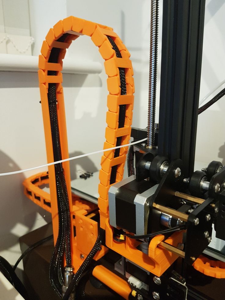 FEYCO-TREFFERT paints and varnishes. ..
16.06.2019 Kulebaki (Russia)
85,000
Line for the production of pallets (can be purchased on separate machines)
Condition: New Manufacturer: TsMA (Russia)
In stock
We offer a set of equipment for the production of high-quality pallets. blanks - boards and "checkers" - TD-4.4 and TSh-8, as well as...
03/23/2020 Kulebaki (Russia)
packaging and labeling machine
Condition: used Year: 2008 Manufacturer: KRONES/KOSME (Germany)
unused equipment: 1 for sale. Packing machine for creating group packaging mod. WRAPAPAC WT - 0346, manufactured by Krones AG, Germany. Year of manufacture of the machine-2008 In operation...
11/07/2017 Kulebaki (Russia)
Hydraulic press "Eco-20"
Condition: New Manufacturer: EcoMachine (Russia)
Available
Available
- New presses of our own production.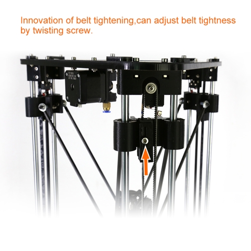 - Vertical presses - 8 models...
11/29/2022 Kulebaki (Russia)
225 625
Press for Pressos Eco-8
Status: New Manufacturer: Ecostens (Russia)
Available compression 8 t Pressing cycle 30 sec Bale wrapping Manual Weight 455 kg Feed opening, HxW 500x600 mm... Kulebaki (Russia)
150 100
Press for ECO 12
Status: New Manufacturer: Ecosteks (Russia)
Available Squeezing 12 tons 12 t Hand weight 515 kg Loading window, HxW 500x900 mm Bale dimensions, HxWxD 700x900x600 mm Motor 2.5 kW 16A 380V Stroke 700 mm...
11/29/2022 Kulebaki (Russia)
170 050
Press for waste paper L in stock L
Status: New Manufacturer: Ecosteks (Russia)
Available in the stock Press for the waste paper! Press from the manufacturer! Run on your raw material before buying! New! Waste paper press - a device that.