3D printed physics experiments
3D printed Laserlab | S'Cool LAB
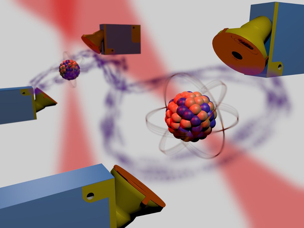
Space, time, and matter are among the most fundamental concepts we rely on for structuring our understanding of the surrounding world. In the past, fundamental research has made the most astonishing discoveries on the nature of these and has shown that our everyday understanding cannot be quite right.
Many times, advances in our understanding are closely tied to sophisticated experiments, which are, however, often not easily accessible to a broader public. Now, with the growing popularity of 3D printers, many of those experiments can indeed be conducted at home, on your very desk.
Scope of the project
In this line of reasoning, this project proposes a Do-it-yourself 3D printed Laserlab, which allows for hands-on experimentation in the realms of Special Relativity and General Relativity as well as Quantum Physics. Technically, the Laserlab consists of 3D-printed optical mounts that are complemented by inexpensive components such as screws, magnets, or mirrors. Once assembled, they serve as building bricks for experimental setups, very much like those you would find in a professional photonics laboratory (but for a fraction of the cost).
What you can build
At its heart, the Laserlab is a photonics lab that allows building various interferometry setups, such as a Michelson-Interferometer, a Mach-Zehnder Interferometer, or a Quantum Eraser.
Currently, three major experiments are proposed (but you are free to also devise your own):
- Special Relativity: Set up a Michelson-Interferometer and test the fundamental hypothesis of Special Relativity: the invariance of the speed of light. This idea is at the core of highly counterintuitive phenomena such as time dilation or length contraction.
- General Relativity: It’s only very recently that gravitational waves have been observed by gravitational wave detectors such as LIGO or Virgo.
 In essence, gravitational wave detectors are Michelson-Interferometers, which have been enhanced to greatly increase their sensitivity. Gravitational waves passing through these detectors will result in changing optical path lengths in the interferometer’s cavities and hence shifting interference patterns. The 3D printed Laserlab features a piezo-driven mirror that can be moved in the order of some 100 nanometers (ten-thousandth of a millimeter). This makes it possible to simulate the effect of gravitational waves and thus gain a better understanding of what is happening in large gravitational waves detectors.
 - Quantum Physics: The Quantum World often seems very strange to the point of being barely comprehensible from a common-sense point of view. One of the stranger features is what happens during measurement and how the measurement itself affects what is being measured. A well-known experiment to explore the subtleties of Quantum Physics is the so-called “Quantum Eraser.
 ” With the Laserlab, you can build one and explore the Quantum World for yourself.
Getting started
- Download the manual and the required .stl files.
- Download the provided Arduino sketch.
- Choose which experiment you would like to build.
- 3D print the mounts you’ll need according to the specifications in the manual.
- Order screws, magnets, a steel base plate, and optical components from your favorite supplier.
- Assemble the lab and set up the experiment.
- Explore!
physics | High School Maker
3dprinter, physics, presentation
Steve Leave a comment
3D Printing Allows for the Investigation of Real World Problems
Physics is one area that should be immune to the sentiment of, “When am I going to use this?” Yet I’ve heard this voiced in my class and to be fair I doubt many of my former students have ever needed to determine the flight time of a projectile launched in a vacuum or the speed of a hoop rolling down a ramp in their careers. 3D printing gives you the opportunity to either create or help your students create equipment to address engaging problems that go beyond the textbook. These problems might be the subject of national news or maybe just viral videos. In this presentation, I will share projects done by and with my students that benefited from the inclusion of 3D printing.
My Presentation as a PDF
Software I use for 3D Design:
-
- Tinkercad – Free, simple, online (my quick overview)
- OpenSCAD – Free, write a program to design objects
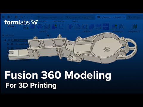
- AutoDesk Fusion 360 – Free for Education
Projects:
-
- Wind Turbine Model Building
- Create a Cell Phone Holder
- Football Concussion
My Physics Models:
-
- Slow Acceleration
- Rotational Inertial Demonstrator
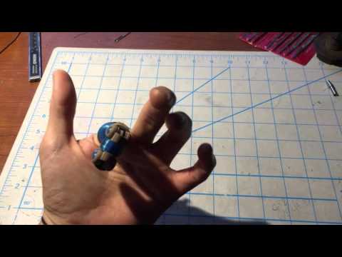
- Adjustable Fidget Spinner – Photogate Mount
- Phone Scope Mount
- Table Clamp
- Centripetal Force Demonstrator
- Vernier Force Plate Attachment
- All of My Models
3dprinter, physics
Steve Leave a comment
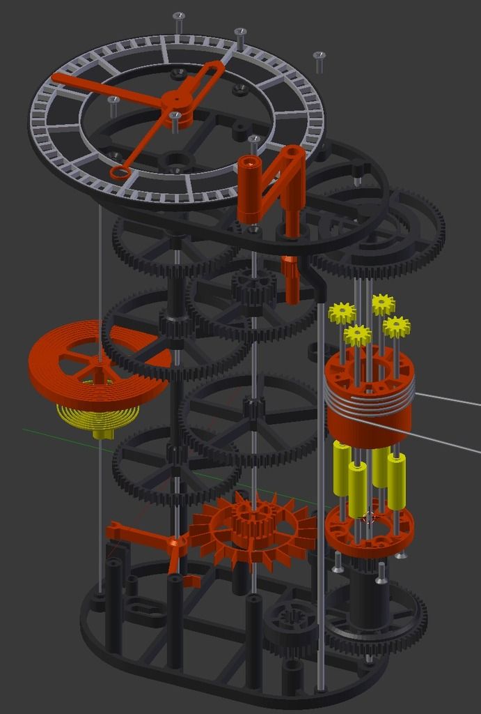
Many years ago I saw a really cool apparatus invented by Steve Rea, a local physics teacher, for experimenting with concepts of rotational motion. It was a simple system of stacked pulleys of decreasing diameters. Metal rods with weights allowed the moment of inertia to be easily varied. The device was elegant in its simplicity and offered the opportunity for incredibly rich investigations and discussions.
Then, last year, the fidget spinner craze happened. Several months ago I was having a conversation about 3D printing with Andy Mann. He told me how his son designs and prints his own fidget spinners. Andy also related how his son is so into this he found a YouTube video showing him how to degrease his bearings to make them spin longer.
It took a day for the light bulb to turn on. Two days after that I had a set of bearings from Amazon (I love Prime) and my prototype of a 3D printed fidget spinner. I started with this to make sure the degreasing worked and that I had dialed in the perfect size to hold the bearing.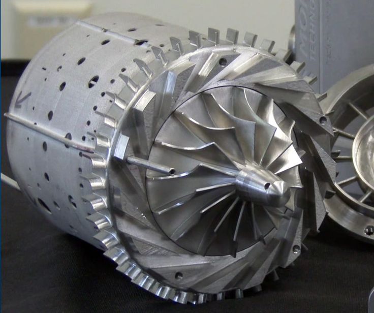
With that done I knocked out a quick prototype, which failed utterly. Two versions later and I had it done. You can find my design on the Thingiverse and if you’re interested you can tweak it however you’d like in Tinkercad.
There are three different pulleys to provide different amounts of torque. With an extra set of hex nuts the washers can be positioned different distances from the center of rotation changing the moment of inertia. There are a lot of experiments that students can do to investigate rotational motion and the transfer of energy.
Diameters of the three pulleys:
-
- 24.5 mm
- 49 mm
- 73.5 mm
Parts List: (about $10 in parts/device)
-
- 2 each Skateboard Bearings, 608ZZ 8x22x7
- 4 each 6″ long 1/4″ bolts
- 12 each 1/4″ hex nuts
- 40 each Fender washers, 1/4″ hole 1.25″ diameter (the number of fender washers can be varied)
As I mentioned above, the bearings need to be de-greased first.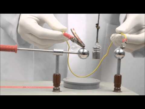 The grease protects the bearings from water and road grit, but it will keep the bearings from spinning freely. I used acetone since we had it in the chemistry supplies. I just dropped them in a small beaker for 20-30 minutes. I found I also had to take them out of the acetone and spin them a couple of times then drop them back in. A lot of the instructions on the net direct you to remove the metal shields. I’ve found you don’t need to do this. However, if you get “sealed” bearings you will need to remove the seals. You need two bearings, one in each end, for full support.
If you want to avoid using acetone do a little googeling for other ways to de-grease bearings. There’s lots of stuff related to fidget spinners kicking around right now.
electronics, engineering, make and take, physics
Steve Leave a comment
I’ve been teaching a semester long electronics class every semester since I started teaching in 2000.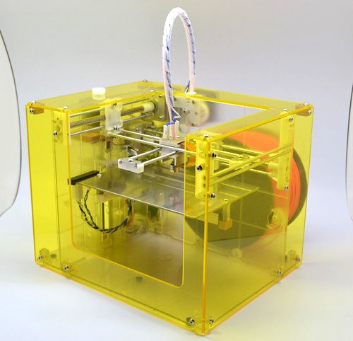 It started as a basic circuits course, but several years ago I started teaching it with the Arduino micro-controller platform. It has undergone several transformations over the years and I’m changing it yet again this semester.
We’re starting with some basic circuit fundamentals. In the past I assumed they would learn these fundamentals as we worked with Arduino. It turns out I was wrong. One of the circuit building things we did this week involved making paper circuits. This worked out really well and gave students a chance to discover differences between series and parallel circuits. They also got to do some trouble shooting to figure out closed, open, and short circuits.
All in all it was a fun project to help set the tone for the semester while also giving us an activity we can refer back to as we move forward.
Recommended resources:
- Paper Circuits Book from Makerspaces.com
- Paper Circuits from SparkFun.com
- High Tech Low Tech
- 1/4″ Copper Tape from Amazon
- 3V Coin Cells from Amazon
cheap tech tool, make and take
Steve Leave a comment
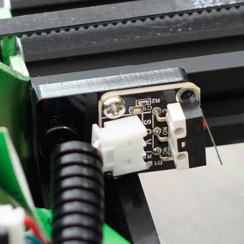
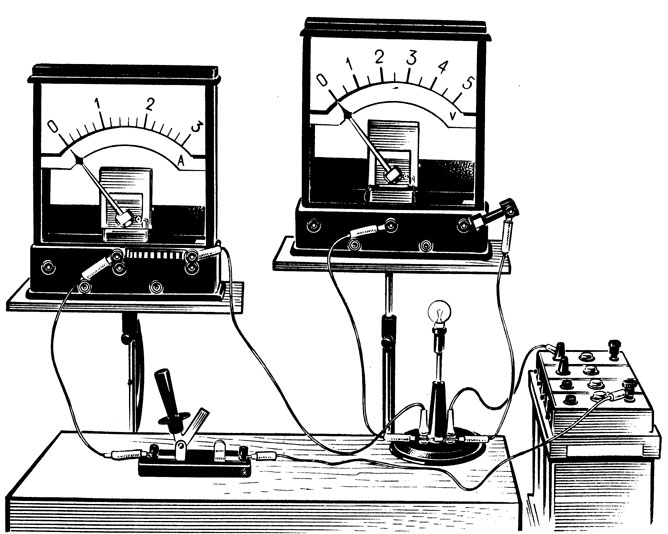
We have a new chemistry teacher this year.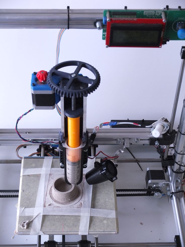 At his old school he used these conductivity meters from Flinn Scientific. He said they work really well. He had students use them to make qualitative comparisons of the conductivity of different solutions. The only problem I saw was their price tag. They are $22 ea. This is not horrible, but there really isn’t much to them. So I decided to see if I could make them cheaper.
Turns out it was pretty easy to source the components to place the cost at no more than $1.50 ea. So, for the price of one of Flinn’s meters I can make a classroom set.
I created a set of instructions for making your own: Conductivity Meter Tutorial (PDF)
I used Plasq’s ComicLife to create this. I’d forgotten how much I enjoy using this for making tutorials.
Parts:
- Battery Holders: http://amzn.to/2jiwYgV
- Screw Terminals: http://amzn.to/2jivpPU
- Porto-Boards: http://amzn.to/2iwaQ1p
- Resistors 1000 ohm: http://amzn.to/2iTqnG0
- Resistors 100 ohm: http://amzn.
 to/2iwfooj
3dprinter, arduino, cheap tech tool, physics, probeware
Steve Leave a comment
I gave a presentation a couple months ago at the Spring meeting of the Michigan section of the American Association of Physics Teachers highlighting a project a pair of my electronics students did last school year. My students used an Arduino to read a 250g accelerometer to investigate the force a brain might feel in a violent football tackle.
From an Arduino point of view it was a trivial program. However, it was still a cool project for a variety of reasons. There were many opportunities for problem solving. They had to figure out how to embed the sensor in a meangingfull way, mount the helmet, and simulate a rough tackle. First task was determining how to mount the sensor. They asked if they could 3D print a head. This seemed reasonable to me, but I wasn’t sure if they’d have to design it or if we could find one.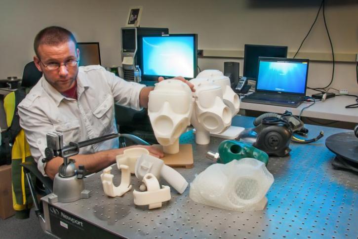 The head of Stephen Colbert was readily available and made us laugh, so that’s the one we printed after modifying it to accommodate the sensor. In retrospect this was not the best head to print as Colbert’s hair when 3D printed doesn’t squish the way real hair would. For this project it worked out fine, but for a side impact would not be ideal.
I really like this project because it gave students a chance to investigate something of interest to them that is also very topical. As football players, this was of direct interest to them and something with wider potential impact as well. When they finished it I immediately wanted to share this project with other physics teachers. It would be cool to see other teachers working with their own students to do similar projects. However, whenever I try to show teachers how to use Arduinos to collect data, their eyes start glaze over as soon as the code hits the screen.
I decided to attempt to meet my physics colleagues where they are rather than where I am.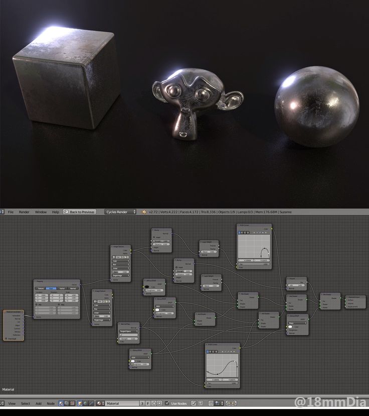 Most of the physics teachers I know have access to either Vernier or Pasco interfaces and sensors. At our school we have Vernier, so that’s what I used. I assume you could do something very similar with Pasco equipment. Vernier sells a cable you can use to make your own analog probeware. It turns out this was very easy to attach to our $30 accelerometer.
The Black Wire goes to GND, the Orange Wire is +5V so goes to the VCC, and the Red Wire attaches to OUT. The other wires were not used. All you need to do is solder these three wires to the sensor and plug it into a LabQuest or LabPro. This is something pretty much anybody can do. However, if you’ve never soldered before I recommend this tutorial from SparkFun Electronics.
The 250g Accelerometer we used is an analog sensor. This makes it easy to interface with Vernier hardware. Nerd Alert: If you need to know, basically we are using it as a voltage comparator. On the LabQuest (or LabPro) we set up our sensor to read Raw Voltage (0 – 5V). For our sensor, zero volts corresponds to -250g’s, five volts with 250g’s, and at 2.5 V we have zero g’s. In reality the 5 V wire gave me 5.2 V (the USB standard is 5 V but can be up to 5.25 V or as low as 4.4 V), so zero g’s was at 2.6 V and 250 g’s would be 5.2 V. Since the output from this sensor is linear, I used the LoggerPro program to convert the voltage readings to g’s by creating a “New Calculated Column”. I ended up with a slope of (500 g’s)/(5.2 V) and a y-intercept of -250 g’s.
The graph of my calculated column resulted in a graph of force vs. time. In the example graph below, the hit lasted for about 0.003 s and reached a peak of just over 63 g’s. Based on readings from the literature, a hit of this magnitude and duration would be unlikely to cause a concussion.
With the growth of the Maker Movement there are now a lot of cheap sensors out there that can be interfaced in exactly the same way. Adafruit makes a 200g 3-axis accelerometer that looks promising, but you’d need 3 Vernier cables to read all thee axises simultaneously (also true with Vernier’s 3-Axis Accelerometer).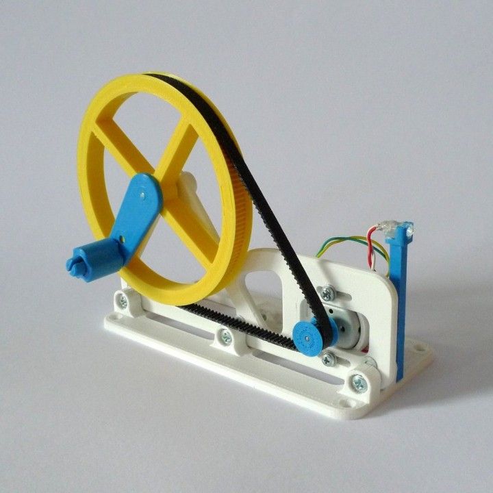 I’ve also been thinking about using some flexiforce pressure sensors to measure the force/area actually applied to the head in a collision. This would be a simple modification of this lesson on the Vernier site.
3dprinter, physics
Steve Dickie 3 Comments
This week I went high-tech to go low-tech. When I taught physics I taught with a student centered pedagogy called Modeling Physics. In Modeling we have student collect data and then use that data to construct models to explain physics. Basically students do labs, graph the data, find an equation that fits their graph and then they turn that equation into a generic equation that can be used in other situations. Everything works great if you can get the students to collect really clean data and if you can actually convince them to think.
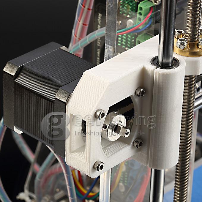
I don’t teach physics anymore, but our new physics teacher, Vance, also uses the Modeling Method.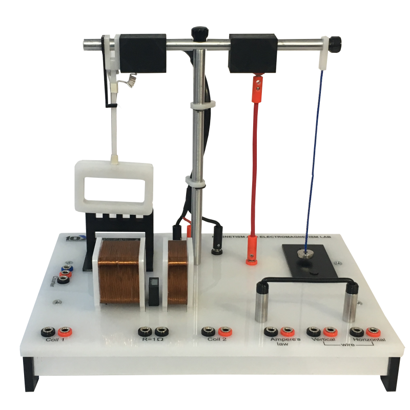 He built some apparatuses last week end to collect really good acceleration data. This is just a wood disk with a golf tee glued to the center of each side. This rolls down a pair of rails and is slow enough to allow students to get some really good data. I’d thought about building these myself in the past, but I knew it would be hard to do and that I’d probably screw it up. So I never constructed any. Vance did a fine job in his construction, but he ended up having all the problems I knew I would have had.
Enter the 3D printer. Looking at Vance’s system I knew I could knock something out on the 3D printer that would work. This is one of the coolest things about owning a 3D printer. You will see problems and begin to envision solutions. Once you start doing this the easier it becomes. The only risk is that you will quickly assume the 3D printer is the best tool for all jobs. As awesome as it is, it is not always the best way to solve every problem.
I spent about 10 minutes in Tinkercad on my design and then it took about an hour and a half to print.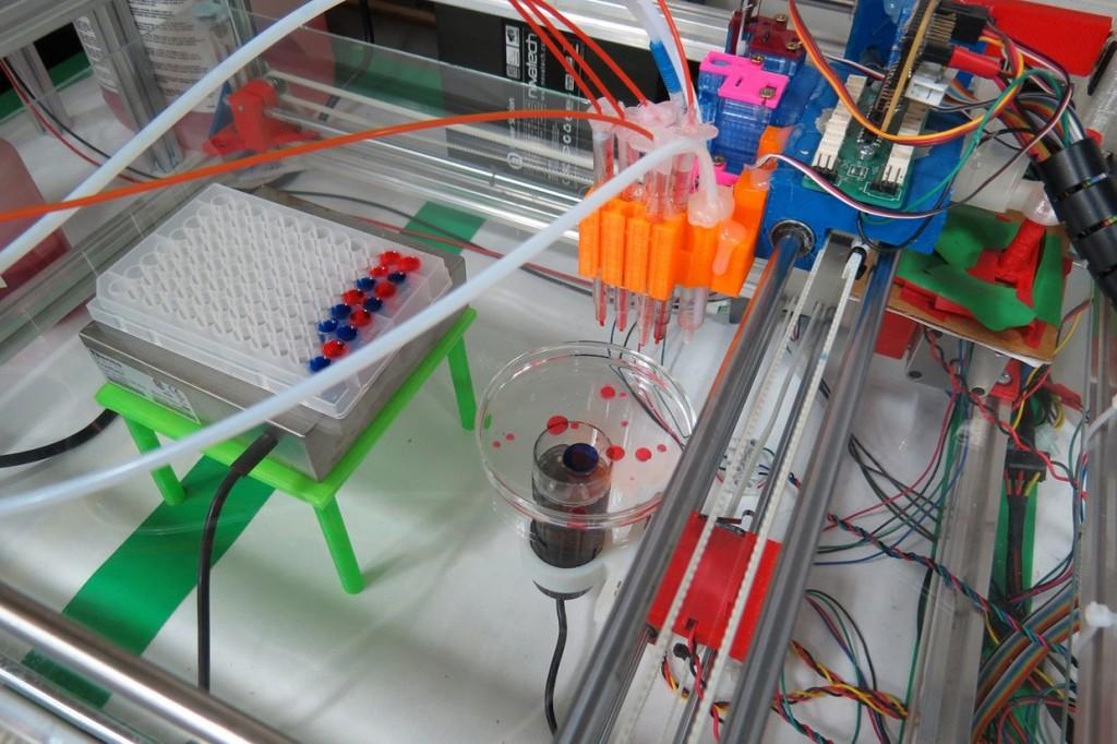 Vance tells me it worked great for the lab. I’m already envisioning modifications for future investigations. The design could be easily modified to investigate rotational inertia and energy, but maybe I’ll leave it to students to create these new designs.
Acceleration Paradigm Lab – Teacher Notes
Materials (for each group):
- 2 bricks with holes or grooved sides
- 2 five foot sections of electrical conduit
- 1 wood disk with a golf tee sticking out of the center of each side, or 1 3D printed disk with cones out of each side
- Dry erase marker
- A metronome set to 60 peats/minute (or a computer program) – One for the entire class
Basic Procedure:
- Set the conduit up as a pair of rails spaced appropriately for your rolling disk
- Let the disk roll down the rails
- Mark the position of the disk at 1 or 2 second intervals
- Create a position vs. time graph and find the equation that fits the data (should be a quadratic)
- Create a velocity vs.
 time data set and graph from the position data using the secant line created by each pair of points on the position graph. This graph should be linear.
 - Note: If the incline is too steep it will slide rather than roll.
Class discussion:
- I always have students use the actual variables in their equations, no x’s or y’s. In addition all constants need units.
- Once students have equations for both their position and velocity graphs I ask them what each constant represents and how they know. This is pretty easy for the velocity graph, but a little harder for the position graph. It leads to some great conversations and ultimately to a pair of generic equations we will use for the rest of the kinematics unit.
My 3D Model:
- On Thingiverse
- On Tinkercad: the Disk, the Side Cones.
This is a part 6 of my series on 3D Printers in Education. Go back to earlier parts in the 3D printer series: Part 1, Part 5
make and take, physics
Steve Leave a comment
Tomorrow, Saturday 10/4/14, is the fall meeting of the Michigan Section of the American Association of Physics Teachers. If you’re interested, it will be at the University of Michigan, Flint. For more information you should check out the meeting page.
Anyway, Jim Gell and I will be running a Make and Take in the afternoon. One of the things we will be doing again is the ever popular LED Color Mixer. We’ve done this before as a modified version of the LED mixer presented by Chris Chiaverina in the Physics Teacher. This is a pretty cheap demo device, but in the past we ordered $1-2 LED, $1 battery holder, $0.50 ping pong ball, and 2 AA batteries. Cost for each one was between $3 and $4. This was a bit costly to run as a Make and Take. It also involved soldering, which while not particularly difficult did require the direct supervision of someone.
We will be doing the same project on Saturday at a cost of less than $0.20/device with no soldering required. This project is cheap enough that you can have participants make one on site and then send them home with a couple extras to make with their classes. They’re so cheap that a teacher could have each of their students make one to take them home and explain how they work to their families.
The parts list:
- RGB flashing LED – $3.05 for 50 LEDs
- 3v Button cell battery – $6.02 for 50 Batteries
- Electrical Tape
- Scotch Tape
- Tissues
- 2.25″ Cube template
- Old Overhead Transparencies (optional)
I should note that while both the batteries and LEDs are sourced from Amazon, the LEDs come from China and will take a few weeks to arrive. While the LEDs are cheaper than we’ve been able to get them in the past the real savings is from the batteries. In order to make things extra cheap I replaced the ping pong ball with a paper cube.
Simply bend the leads on the LED as shown. The shorter of the two leads goes to the negative side of the battery with the longer going to the positive. Use a little electrical tape to hold the leads to the battery. If needed, slip a small strip of overhead transparency in between one lead and the battery to act as an “off switch”.
Print out a copy of the 2.25″ Cube Template and assemble. Before closing the last flap put 1/2 a Kleenex in to help diffuse the light and cut a hole in one side. The simply slip your LED and battery in and bask in the color changing goodness you have created.
How would you use this with your students? Share your thoughts in the comments.
3dprinter, physics
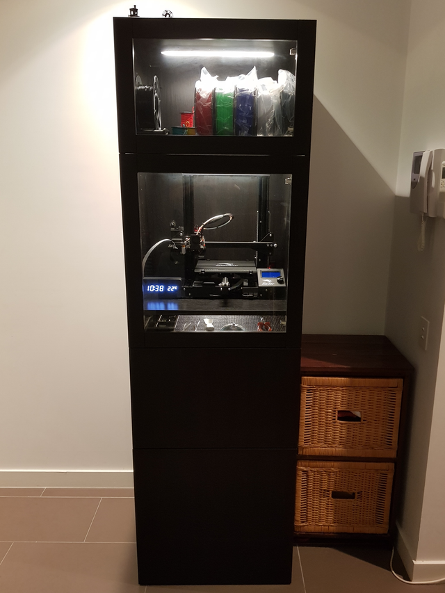
Steve Leave a comment
Almost a year ago I managed to find money to buy a Makerbot Replicator for my classroom. It really is like magic. Most of the year we’ve really just been playing. Printing out cool stuff from the Thingiverse and a few project enclosures for electronics projects.
I’d been wanting to do a cool design project with my physics students, but never really knew what it should be. 3D design is not a skill in the wheelhouse of virtually any of my students (our CAD program died a few years ago). It turns out there is a cool program that lets you create 3D designs programmatically. It’s called OpenSCAD. The beauty of this is that you can create or find a program that generates the 3D design. Then all you need to do is change some of the variables to get a new design.
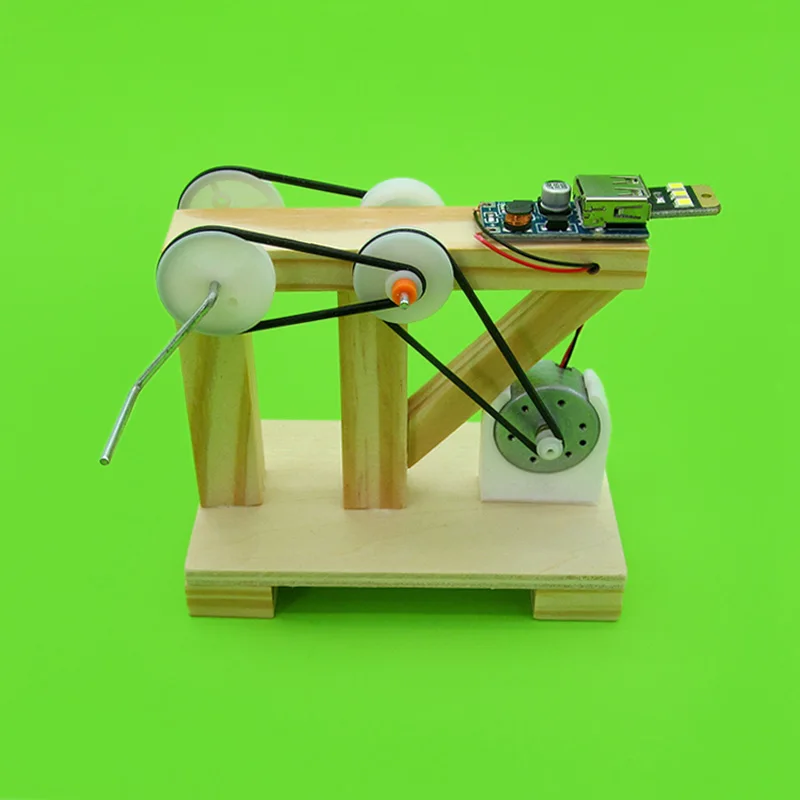
I decided to give this a try in my physics classroom. We’re in the time of year after the seniors are gone and now the juniors feel like they should be gone as well. I found a cool Mini-Wind Turbine model on the Thingiverse that was created in OpenSCAD. I played with it a bit to figure out exactly what the variables did and then introduced it to the class. Next year I’ll let them figure out what each of the variables does for themselves.
Each of my two physics classes picked two parameters to vary. We ended up with:
- Length
- Width
- Angle – Which was really twist
- “Fat Point” – Ratio of top length to bottom length
We created 5 different versions varying our on parameter. I let the students decide what they wanted to set the parameters to as long as the blade was not absurd.
Actually we did end up with an absurd blade when it came to twist, but the group that wanted it were convinced it would be the best. So I went ahead with it.
I asked students to graph and find the relationship for each of our four parameters. Unfortunately none of the parameters gave us very good mathematical relationships. I think we might have needed bigger variation in some and more data points in between in another. Next year I may have students fill in some of the gaps.
Once data were analyzed I asked them to design the perfect wind turbine. Some groups relied on their data and some did not. It should really come as no surprise that the groups that relied on the data did the best. Of these most just picked the one best data point in each and put them together. The very best one extrapolated from their data to predict a better solution. It’s nice when things work out the way the should like that.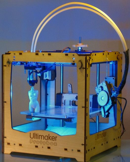
The best part for me was how surprising our results were. We all had the image of the big majestic wind turbines in our heads. This, however, was not the shape that we found to be the best. The one we found to be the best looked the least like our pre-conceived notion. It had fat stubby wings rather than long and thin.
Some nuts and bolts details:
- 3D Pinter costs $2000ish
- Plastic is fairly cheap. If I had to estimate, I used between $10 and $20 worth of plastic on this project.
- One full set of 15 blades (3 each of five different states) takes between 3 and 4 hours to print. One set all by itself 40 min to an hour. Time varied depending on the design.
physics
Steve Dickie 1 Comment
If you follow my blog you know I’m a big fan of the new iBooks and iBooks Author. What I wanted to mention today is a cool tool called GeoGebra.
“GeoGebra is free and multi-platform dynamic mathematics software for all levels of education that joins geometry, algebra, tables, graphing, statistics and calculus in one easy-to-use package.
It has received several educational software awards in Europe and the USA.”
It’s pretty cool. After playing with it a little I see some real potential here not only for math, but also science. Below is an interactive I made after playing for only a few minutes. It models a position time graph for an object moving with a constant velocity. You can change the Velocity or the Starting Position (xo).
It literally took me no more than ten minutes to make this having never worked with GeoGebra before. Anyway I was looking at GeoGebra as a way of creating interactive content for iBooks. Anthony DiLaura (@anthonydilaura) has been doing this already. He uses Tumult Hype to take GeoGebra output and get it into a widget for embedding in iBooks. I’ve come up with a slightly different way and easier way, but Anthony’s way is better in some ways.
In order to put your GeoGebra Content into iBooks Author you must:
- Download a Beta Version of GeoGebra (4.2 or 5.
 0) and create your interactive
 - File->Export as “Dynamic Worksheet as Webpage (html)”
- Click on the “Export as Webpage” Button
- Click on Advanced (near the center of the window)
- Set width to 820 and height to 520
- Place a checkmark in the Export to HTML5 box
- Then Export. Save as index.html somewhere you can find it
- Download my sample widget and unzip.
- Replace my index.html with your index.html
- Rename the sample folder to: your name.wdgt (Adding the wdgt will turn the folder into a widget file. You can access the individual files again by right clicking on the widget file and selecting “Show Package Contents”)
- Embed your widget in iBooks!
I should note one thing. This method will only work if you have an internet connection to the iPad when you’re using it. I have been a bit daunted when it comes to making offline widgets. Check out this discussion forum if you want to try to create widgets for offline use.
There is a lot of potential in GeoGebra. Not just for me as an educator to make interactive elements for my students, but for my students to create them as well. I really wish I discovered this at the beginning of summer rather than the end…
physics, probeware
Steve Dickie Leave a comment
Well, as of this morning my handouts still haven’t appeared on the ISTE-NECC site for my session, so I’ve converted my pdf files to jpg and uploaded them to Picasa Web Albums (owned by Google).
Here are all the handouts I had posted to the backboard behind my table. I created them using Comic Life on my MacBook.
- Build your own probeware
- Sound Science
- Motion with a picket fence
I also have them as pdf files. If you’d like a copy of the pdfs just shoot me an email and I’ll send them along ([email protected])
You may also want to see my step by step instructions over on instructables. com
com
3D printing is used in particle physics experiments
Scientists are now actively investigating basic concepts in the field of intensity, studying extremely rare processes, such as the transformation of muons into electrons. The scientific community took up this issue as early as the 1940s. It is believed that studying this problem is the key to understanding why particles from one category turn from heavy to light, moving to a state with a more stable mass.
Simplifying the concepts as much as possible, we can say that electrons imply an action (for example, an action such as providing light in a house or powering a computer with energy). On the other hand, muons are a more “heavy” form of electrons, but it is not yet fully understood how these particles relate to each other. Physicists assume that by understanding the relationship between muons and electrons, they will be able to understand the essence of the electrons themselves.
A team of researchers is currently working on a tracking system they have named Mu2e. We are talking about a device consisting of small low-power boards that are located at the ends of the "tubes". Cooling lines are a key element of this arrangement, as they allow the removal of heat that would otherwise fill the necessary vacuum. Achieving the necessary cooling was not easy, since there was very little space in the system to accommodate such lines.
Designers have also experienced that machining curved metal parts with oblong tube holes has been difficult and expensive until recently. Now this problem has been solved with the help of 3D printing, which allows the production of a high-tech version of parts from transparent plastic.
The researchers intend to use a 3D-printed plastic prototype to run an electrical charge through a tube and "pinch" it with a magnet, much like playing guitar strings. By measuring the received vibration, scientists can determine the benchmarks for the tube to maintain its original straight position throughout the experiment.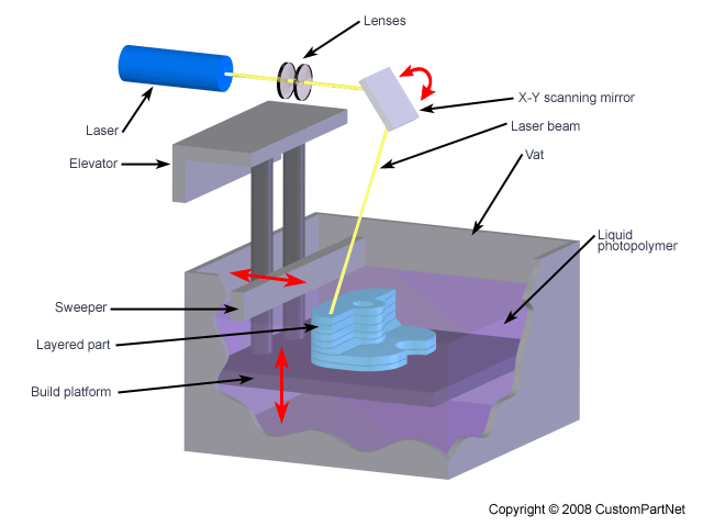
The idea of the Mu2e project is to follow how the muon turns into only one electron, without emitting additional particles. In theory, physicists believe that this is possible, but no one has been able to observe this process in practice.
Such an experiment should be about 10,000 times more accurate than previous ones. The task of scientists is to follow the rapid movement of electrons in order to fix the characteristic energy release of 105 megaelectronvolts that occurs during the decay of the muon. In practical terms, this means that Mu2e developers need to build a detector using the minimum amount of material. There must be so little material that, with a certain degree of relativity, one can say that it does not exist at all.
The tracking system itself consists of the thinnest tubes of metallized Mylar. The tubes are only 15 microns thick, making them the thinnest in the history of physics experiments.
The tubes are filled with argon and carbon dioxide, and a thin wire runs through the middle of the inner cavity. Circuit boards mounted on both ends of the tube are designed to record any electrical signal that occurs when electrons collide with the gas inside the tube. The researchers say they will be able to measure the time it takes the electrons to reach each end of the tube to plot the overall trajectory of the particles.
3D-printed eggs helped unravel the mystery of nature
News
American scientists have revealed the secret of bird eggs, or rather their characteristic shape. 3D printing technologies helped to conduct experiments without the threat of extinction of protected species of birds.
Looking at the scrambled eggs gurgling on the table of a 3D printer, one involuntarily wonders why bird eggs have such an unusual shape. The question is interesting, because one fictional country was even mired in a series of bloody civil wars, and all because someone got into the bad habit of cracking eggs from the wrong end. The secret was solved by a two-person scientific team - University of Illinois biology professor at Urbana-Champaign Mark Hauber and Hunter College graduate graduate Ian Hayes.
The eggs of guillemots were of the greatest interest to scientists due to their pronounced, almost conical shape. Being responsible researchers who care about nature and do not want to clean the floors, Mark and Ian decided to abandon experiments with natural samples and printed replicas on a 3D printer. Subsequent tests on inclined surfaces confirmed the conjecture of the academicians: such a shape complicates the rolling of eggs, rounding the trajectory. It is quite logical, because those same guillemots like to nest on sheer cliffs, so that with the slightest movement, the egg can fall into the abyss and break. To smithereens.
“Science knows very little about how guillemot egg shape affects stability and survival under these nesting conditions. Many scientists support the theory that this shell geometry reduces the chance of rolling off a cliff, but previous studies have not looked at specific factors such as elongation, asymmetry and taper,” says Professor Hauber.
Mark and Ian, on the other hand, conducted a comprehensive study comparing 3D printed guillemot eggs with replicas of other bird eggs that differ in size and shape. During the experiments, it turned out that the greater the elongation, the higher the probability of rolling, and the high taper of murre eggs reduces displacement by increasing the curvature of the trajectory during rolling and allows you to stay on surfaces with an inclination of the order of two degrees, or even more. How exactly did this form come about? Scientists suspect that natural selection is to blame, although the defenders of the concept of creationism have their own opinion on this matter. To come to a consensus on which end is best to break the egg, so far, too, failed. The report of the scientific team is published at this link.
The 3Dtoday team wishes everyone a Happy Friday and a nice weekend!
Follow author
Follow
Don't want
7
More interesting articles
9
Subscribe to the author
Subscribe
Don't want
IRNITU students Georgy Byzov and Anatoly Semchenko have developed a 3D printer that works with real snow...
Read more
5
Follow author
Follow
Don't want
Compared to traditional casting, 3D printed sand casting has several advantages...
Read more
82
Subscribe to the author
Subscribe
Don't want
Collaboration 3D
We are pleased to present you our joint development with Speci.