3D printed mold for carbon fiber
Tutorial: How to 3D Print Molds for Carbon Fiber Parts
Introduction
In this tutorial, we skip the process of using a pattern to create a mold and directly create a mold using 3D printing. This tutorial is a bare-bones carbon fiber process meant for those without the specialized equipment needed for more technical processes and high-temperature epoxies.
We will be taking a FFF print with the barriers already modeled and release-coating it before manufacturing the carbon fiber part using a simple hand layup process. Non-cosmetic parts can be used directly from the mold, however, the surface will be slightly compromised by the resolution of the 3D print and limitations of a hand layup process. To bring the finish up to a perfect standard the part can be coated in XCR coating resin and flatted and polished to a high-quality finish.
Material Compatibility
PET-G filament is highly recommended due to its good release properties with the epoxy resin. ABS should be avoided as a direct mold material as you may find if difficult to get a good release from epoxy resin.
After 3D printing, the mold should be prepared with a release agent. The most reliable release agent for this process is PVA release agent, as it helps to smooth out layer-lines while providing a reliable release from the epoxy resin.
The resulting mold from this process will work with most conventional resin systems, such as epoxy polyester and vinylester. Generally molds made in this way are best suited to hand layup processing (with or without a vacuum bag). It would also be possible to process using resin infusion but due to 3D prints generally not being 100% airtight, an envelope bagging method may have to be used. Molds made with this process are not suitable for elevated temperature cures, as used in prepreg production, even when the HDT of the PETG is not theoretically exceeded, we have found the stress of the vacuum bag will lead to excessive warping and distortion.
Materials & Equipment Needed
- 3D Printed Part – For this tutorial, we use the Ultimaker S5 which is an affordable, end-to-end 3D printer with hundreds of ready-to-print materials.
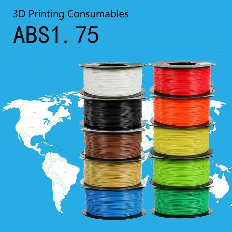
- PETG Filament
- PVA Release Agent
- XC110 210g 2×2 Prepreg Carbon Fiber: We are using three plies in this project but any dry composite reinforcement can be used.
- EL2 Laminating Epoxy: Which is specifically designed for wet layup processing and offers excellent strength and wet-out performance. The back of the part is then finished with our Economy Peel-Ply which provides a neat inner surface.
- XCR Coating & NW1 Polishing Compound (optional): Use these to post-process your carbon fiber part, providing a better cosmetic finish on your end product.
Ultimaker S5
A large, easy-to-use 3D printer with massive, ready-to-print material ecosystem.
Learn more >
Kimya PETG
An affordable, highly versatile, and easy-to-use 3D printing material.
Learn more >
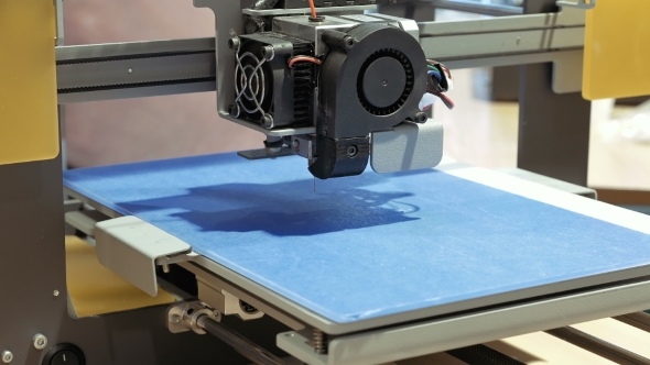
The Process
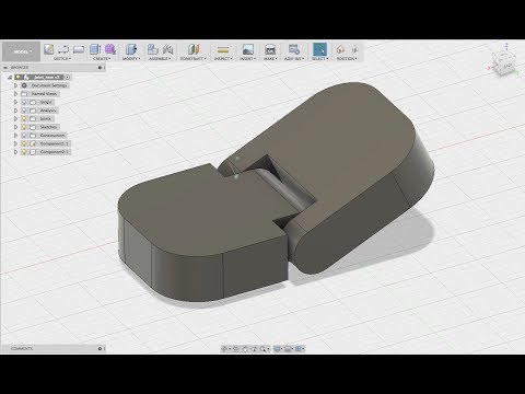
1. Create the PrintDesign and 3D print your mold with any flanges or extensions required to aid in the layup. We suggest using PET-G for directly printed molds due to its reliable release properties. Printing at a higher resolution will provide a smoother mold surface that is easier to release from. For this project we printed with ‘standard’ CURA Slicer settings with a 0.15mm layer height. If possible, orient the part so that the layers are printed parallel to the direction of release of the part, this will reduce the mechanical lock presented by the print surface. That being said, as long as you have a draft-angle of 5deg or greater you can still get a good release, even if the layer-lines are perpendicular to the release direction.
For larger molds, BigRep 3D Printers provide build volumes up to 1m3, or your design can be printed in sections and then bonded together with an appropriate adhesive.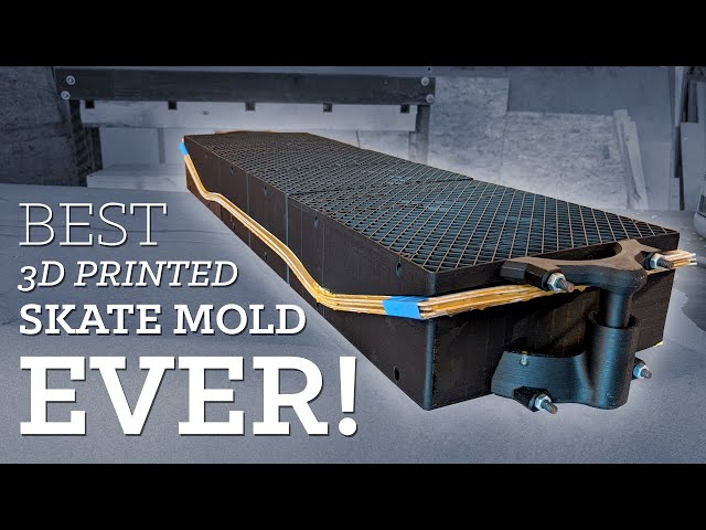 Although, PET-G may have some bonding issues due to its release properties.
Although PET-G will offer an inherent release with epoxy resins a release agent is still required to ensure that the part will separate from the mold. We recommend PVA release agent, as it offers a very fast and reliable release in this process. PVA is applied in a single coat either by wiping or brushing an even film over the mold surface. This coating should be liberal but not so thick that it causes runs. Once applied, the PVA release agent should be allowed to dry as room temperature, typically this will take around 30 minutes.
3. Laminate the PartFor this project, we are using the EL2 laminating resin. Be sure to accurately and thoroughly mix the resin with its hardener. It is best practice to pour from the first container into a second and mix again to ensure there is no unmixed resin.
Before laying the carbon, the mold should be coated in a film of resin. When hand laminating you should, wherever possible, lay the carbon onto the resin and wet out the fabric with resin from underneath. This will help to ensure proper wet-out and will reduce air entrapment. For small intricate parts, a laminating brush will be needed but for larger or flatter moldings, a roller or squeegee can aid the wetting out. For a wet lay-up you are typically aiming for a fibre to resin fraction of 1:1 so for every 100g of fibre you will use approximately 100g of resin.
With parts 3mm thick or less, it is usually possible to laminate all of the layers in one single operation. For thicker parts, it may be necessary to divide the layup into multiple laminations to reduce the effects of shrinkage and the possibility of a thermal runaway or ‘exotherm’.
On this project, after the reinforcement is laid, a layer of peel-ply is used as a final ply to create a neat finish on the inside of the part, which also provides a good surface for subsequent bonding operations. With the peel-ply laminated, the part can then be left to cure at ambient temperature. Cure times will vary depending upon the hardener speed and the room temperature but will typically range between 12 and 48hrs.
CAUTION: Do not leave the mixed EL2 resin in the bottom of the mixing cup if deeper than 5mm. This can undergo a thermal runaway which can be potentially dangerous. Excess resin should be poured into a tray to increase the surface area and/or the container should be moved to a safe outdoor location in case of overheating.
4. TrimAfter demolding, trim and finish to give a clean edge to the part. For our project, we used a Dremel type tool fitted with a 32mm Permagrit cut-off wheel which is an excellent all-round trimming tool and lasts for hours of continuous use. The edges were trued up using a sanding block and finished with 240grit paper. If you are happy with the results as left by the XCR coating, the part could be used as is but generally, sanding and polishing the part would be preferred as it will leave a more consistent and professional finish.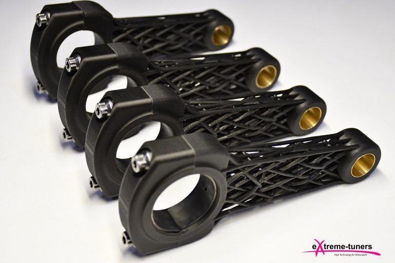
In order to achieve a good cosmetic finish without pinholes and print layer-lines, the part can be coated with a resin or clear-coat. To prepare the part, the surface will need to be abraded with 400grit wet and dry sandpaper to provide a good key for the coating.
If your part has any voids or large pinholes, use resin to fill them. For larger voids, a dam created from flash release tape can help to hold the resin back from running out, then use either the EL2 laminating resin or the XCR coating resin to fill it. After the repairs have been made, they should be left to cure and then sanded back in flat with 400grit paper to level with the surface of the part.
6. Coat with XCR Coating ResinWith the part fixed and sanded, it can now be coated to provide a smooth glossy and durable finish. It is possible to use a clear-coat automotive spray but for this but in this project, we are using the XCR coating resin which will provide a very durable finish and can easily be applied with a brush.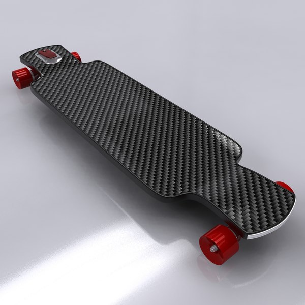
Coat your part in XCR epoxy coating resin—typically around 300 grams per square meter for each coat. Plan on mixing more than is needed to allow for wastage in mixing cups, brushes, etc. The hardener should be added to the resin in the exact ratio of 100:35, as accurately as possible for small batches of resin scales (within one-tenth of a gram accuracy will help). Mix the resin in one cup, then transfer to a second cup and mix again to ensure that there is no unmixed resin trapped.
Use a brush to apply a thin, even coat over the surface. Do not overload the surface as this will lead to runs in the coating. After applying the coat, check a few minutes later for any runs, removing any excess resin a brush.
Depending upon the finish left by the first coat, as second may be required if any of the surface irregularity has not been covered. The second coat should be applied when the first has reached the B-stage. You can identify the B-stage by touching your print with a gloved finger, it should be tacky but leave no residue, typically around three hours for the XCR, but may vary depending upon room temperature. After your second application the resin should be left to fully cure, about 12–24 hours depending upon temperature.
CAUTION: Do not leave the mixed XCR resin in the bottom of the mixing cup if deeper that 5mm. This can undergo a thermal runaway, which will potentially be hazardous. Excess resin should be poured into a tray to increase the surface area and/or the container should be moved to a safe outdoor location in case of overheating.
7. Sand & PolishIf you are happy with the results as left by the XCR coating, the part could be used as is but generally, sanding and polishing the part would be preferred as it will leave a more consistent and professional finish.
The sanding process should start with the finest grade of paper that can be used to quickly flatten down the surface—generally either 400 or 800 grit wet and dry. This is best done wet to prevent the paper from clogging, and the grades should be worked through to a minimum of 1200 grit.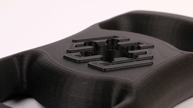 Use a sanding block for flat areas and single curvatures to maintain an even, flat face and the paper along can be used for the remaining curved areas. Whenever changing to a finer grade of abrasive, clean the pattern and change the water to prevent scratches from particles of the previous grade.
After the 1200 grit (or finer), continue with the final polish using the NW1 polishing compound. Unless your part is very small, this is best done with a foam pad on a polishing machine.
Unlike many compounds, the NW1 does not need water and does not quickly dry out. This particular compound is self-diminishing—the more you work it, the finer it gets. You should be able to achieve a full mirror polish in one step. Once buffed, the last residue of the compound can be wiped away with a microfiber cloth, which should reveal a mirror-like polish on your finished pattern.
8. Final PartHow to Make Carbon Fiber Molds & Parts
Name *
First
Last
Professional Email *
Phone *
Organization *
Industry *AerospaceAgricultureArchitectureArts Design and CreativeAutomotive and MotorcyclesChemicalConstructionConsultancyConsumer ElectronicsConsumer ProductsEducation and ResearchEnergyEntertainment and AdvertisingGovernment / Not for ProfitIndustrial Components and ToolingIndustrial Equipment and MachineryMarine/Ship ConstructionMedical and DentalMetal & Steel IndustryMilitaryOther/Serving different industriesPattern Making Molding and CastingPipes and IronworkingPlasticsPrint/Scan/Engineering Service BureauRenewable EnvironmentResellerRetailRoboticsTelecommunicationsTransportation
Location *United StatesCanadaGermanyFranceUnited KingdomItalySpainChinaAndorraUnited Arab EmiratesAfghanistanAntigua and BarbudaAnguillaAlbaniaArmeniaAngolaAntarcticaArgentinaAustriaAustraliaArubaAland IslandsAzerbaijanBosnia and HerzegovinaBarbadosBangladeshBelgiumBurkina FasoBulgariaBahrainBurundiBeninSaint BarthélemyBermudaBrunei DarussalamBolivia, Plurinational State ofBonaire, Sint Eustatius and SabaBrazilBahamasBhutanBouvet IslandBotswanaBelarusBelizeCanadaCocos (Keeling) IslandsCongo, the Democratic Republic of theCentral African RepublicCongoSwitzerlandCote d’IvoireCook IslandsChileCameroonChinaColombiaCosta RicaCubaCape VerdeCuraçaoChristmas IslandCyprusCzech RepublicGermanyDjiboutiDenmarkDominicaDominican RepublicAlgeriaEcuadorEstoniaEgyptWestern SaharaEritreaSpainEthiopiaFinlandFijiFalkland Islands (Malvinas)Faroe IslandsFranceGabonUnited KingdomGrenadaGeorgiaFrench GuianaGuernseyGhanaGibraltarGreenlandGambiaGuineaGuadeloupeEquatorial GuineaGreeceSouth Georgia and the South Sandwich IslandsGuatemalaGuinea-BissauGuyanaHeard Island and McDonald IslandsHondurasCroatiaHaitiHungaryIndonesiaIrelandIsraelIsle of ManIndiaBritish Indian Ocean TerritoryIraqIran, Islamic Republic ofIcelandItalyJerseyJamaicaJordanJapanKenyaKyrgyzstanCambodiaKiribatiComorosSaint Kitts and NevisKorea, Democratic People’s Republic ofKorea, Republic ofKuwaitCayman IslandsKazakhstanLao People’s Democratic RepublicLebanonSaint LuciaLiechtensteinSri LankaLiberiaLesothoLithuaniaLuxembourgLatviaLibyan Arab JamahiriyaMoroccoMonacoMoldova, Republic ofMontenegroSaint Martin (French part)MadagascarMacedonia, the former Yugoslav Republic ofMaliMyanmarMongoliaMacaoMartiniqueMauritaniaMontserratMaltaMauritiusMaldivesMalawiMexicoMalaysiaMozambiqueNamibiaNew CaledoniaNigerNorfolk IslandNigeriaNicaraguaNetherlandsNorwayNepalNauruNiueNew ZealandOmanPanamaPeruFrench PolynesiaPapua New GuineaPhilippinesPakistanPolandSaint Pierre and MiquelonPitcairnPalestinePortugalParaguayQatarReunionRomaniaSerbiaRussian FederationRwandaSaudi ArabiaSolomon IslandsSeychellesSudanSwedenSingaporeSaint Helena, Ascension and Tristan da CunhaSloveniaSvalbard and Jan MayenSlovakiaSierra LeoneSan MarinoSenegalSomaliaSurinameSouth SudanSao Tome and PrincipeEl SalvadorSint Maarten (Dutch part)Syrian Arab RepublicSwazilandTurks and Caicos IslandsChadFrench Southern TerritoriesTogoThailandTajikistanTokelauTimor-LesteTurkmenistanTunisiaTongaTurkeyTrinidad and TobagoTuvaluTaiwanTanzania, United Republic ofUkraineUgandaUnited StatesUruguayUzbekistanHoly See (Vatican City State)Saint Vincent and the GrenadinesVenezuela, Bolivarian Republic ofVirgin Islands, BritishVietnamVanuatuWallis and FutunaSamoaYemenMayotteSouth AfricaZambiaZimbabwe
Subscribe to our Newsletter
- and receive news about 3D printing
Terms of Service *
- I have read and agree to the Terms of Service
Carbon Fiber 3D Printing Guide: Printers and Materials
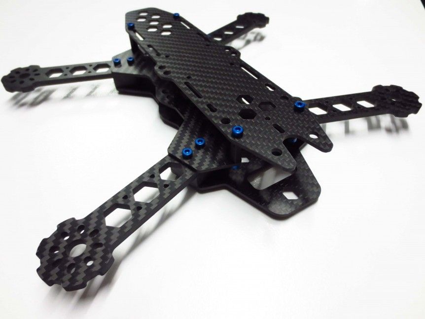
Bicycles, race cars, drones and tennis rackets all have a variety of applications and require high strength and durability without added weight. This combination of properties is typical of carbon fiber composites, which are used in everything from Formula 1 racing car chassis to lightweight road bike frames.
Since many 3D printers commonly use polymer-based materials, including various composites, many people ask the question, "Can a 3D printer print carbon fiber?". nine0003
Indeed, there are two methods by which 3D printing can be used to create carbon fiber parts: supporting traditional fabrication methods with 3D printed molds, or direct 3D printing of carbon fiber composites. In this article, we'll look at traditional fabrication methods as well as new workflows for 3D printed carbon fiber molds and direct 3D printed carbon fiber composite parts.
Combining traditional carbon fiber parts with 3D printing
Carbon fiber is a composite material traditionally made by weaving long strands of carbon fibers together and then bonding them with a polymer. The yarns can be woven strategically so that the strength is directed along one specific vector, or so that the final product has multiple strengths in all directions.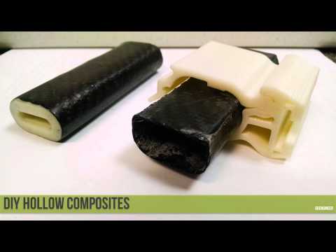 The resulting material is then molded into the desired end product using one of three processes: wet laid, pre-laminated, or resin transfer molding (RTM). nine0003
Wet Laid
Wet laid carbon fiber sheets are cut and pressed in a mould, then dyed with a liquid resin that cures to bind the sheets into the desired final shape. This method requires the least equipment and is the easiest to master for a beginner. Because most of the work can be done by hand, this is one of the cheapest methods, but the trade-off is that the resulting parts are less accurate to the master mold than parts made by other methods. nine0003
Prepreg lamination
In this method, the carbon fiber is already impregnated with resin and then placed in a mold that uses pressure and heat to form the final shape. This method is the most expensive due to the need for specialized equipment to store and process the pre-impregnated sheets, as well as a heated and pressurized forming machine. These factors also make it the most repeatable and consistent, and thus the most suitable for serial production of carbon fiber parts. nine0003
Resin transfer molding (RTM)
In RTM molding, the dry fiber is inserted into a two-part mold. The mold is clamped, after which high-pressure resin is injected into the cavity. This method is usually automated and is used to produce large volumes of products.
3D printed carbon fiber parts
For each of the three previous methods, 3D printing can be used to reduce costs and improve production times. All three traditional manufacturing methods require the use of a mold or multiple molds, which are traditionally created through labour-intensive subtractive processes such as wood, foam, metal, plastic or wax. 3D printing offers an alternative way to make molds. 3D printed molds are customizable and are more efficient and cost effective for small batch or custom production. nine0003
For applications requiring live prototypes, such as the automotive and aerospace industries, the iterative process can require hundreds of different shapes. Producing such iterations with traditional manufacturing methods can be costly and time consuming, so 3D printing provides an efficient way to produce small batches. Although 3D printed molds are not as suitable for high-volume production as metal molds, they can be created in-house, reducing costs, speeding up product development and validation, and short-term production. nine0003
Carbon fiber molds can be made in a variety of ways, but the smooth surface and wide choice of materials for SLA 3D printers make them a common choice for mold making in the factory. SLA-created parts have virtually no layer lines or porosity, so carbon fiber sheets can be pressed tightly into the mold without the fear of creating a textured surface.
Panoz, a manufacturer of racing and sports cars, needed a custom race car cabin duct to bleed the air out of the cabin and cool the temperature inside. In collaboration with DeltaWing Manufacturing, they used a Formlabs SLA 3D printer to print a high temperature resin part and then manually molded that printed part using high temperature epoxy for tooling. By using 3D printing, DeltaWing avoided outsourcing the costly metal mold for this custom carbon fiber part, reducing overall costs and delivery times. nine0003
Carbon fiber wing duct next to two piece mold printed with High Temp Resin made by DeltaWing Manufacturing.
Direct Carbon Fiber 3D Printing
Looking for the best carbon fiber 3D printer? There is a strong demand for workflows that combine the strength, durability and wear resistance of traditional carbon fiber parts with the maneuverability, geometric capabilities and cycling of 3D printing. Therefore, it is not surprising that there are many companies offering 3D printing using carbon fiber, with two methods currently available: printing using chopped or continuous fibers.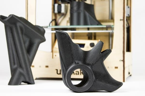 nine0003
Chopped Carbon Fiber 3D Printing
Chopped Fiber refers to 3D printing composite plastic materials that are impregnated with small pieces of carbon fibers. These crushed fibers add strength to the composite, which can be carbon fiber filament for FDM modeling or nylon powder for SLS 3D printing.
The main advantages of chopped carbon fiber reinforced materials over other types based on polymers are that they are strong, light, heat resistant and less prone to deformation. Compared to traditionally molded carbon fiber parts, chopped fiber 3D printing provides increased geometric flexibility in part design, especially in SLS 3D printing, potentially eliminating the labor involved with traditional molding or opening up innovative new opportunities for users to incorporate this material into the working process. nine0003
The Formlabs Fuse 1+ 30W SLS 3D printer enables this type of carbon fiber 3D printing with Nylon 11 CF Powder, the strongest material in the Formlabs SLS material library.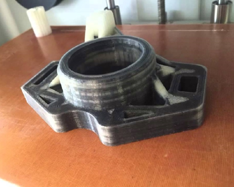 Fuse 1+ 30W is the most affordable high performance SLS printing option for shredded carbon fibers. While traditional industrial SLS machines also offer some carbon fiber materials, the initial implementation costs negate much of the added value of 3D printing carbon fiber parts over RTM or prepreg lamination methods. nine0003
Formlabs Nylon 11 CF Powder is strong, lightweight and heat resistant making it ideal for the automotive, aerospace and manufacturing industries .
Many FDM 3D printers can handle carbon fiber filaments, but these materials are more difficult to print than standard ABS or PLA filaments, resulting in more clogs and more maintenance as the brass nozzles wear out. FDM 3D printers specifically designed to grind carbon fiber filaments are also available but are more expensive. nine0003
The main limitation of chopped-fiber printed parts using both SLS and FDM technologies is that they should be considered as more durable 3D printed parts, rather than a true alternative to traditional woven and continuous carbon fiber parts.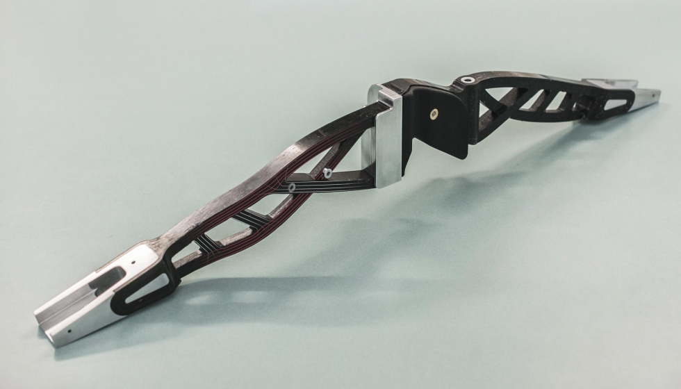 fibers. They also provide the greatest increase in strength by positioning them in the X-plane direction for SLS printing, and in the XY-plane direction for FDM printing. Traditional methods of creating carbon fiber parts provide multidirectional strength through careful planning and placement of different carbon fiber sheets in a preform. nine0003
Carbon Fiber Continuous 3D Printing
Carbon Fiber Continuous 3D Printing is available on some dedicated FDM 3D printers, and the resulting parts are close in strength to traditional carbon fiber parts, but similar to chopped fiber printers FDM, only in the XY plane. In such printers, continuous filaments of carbon fiber are mixed with a thermoplastic and the filaments can be applied strategically to selectively pressurize certain planes or axes. This method can use either a dual extruder nozzle to lay down a combination of carbon fiber and polymer filaments, or a 2-in-1 in which one nozzle lays down the carbon fiber filaments and the other heats and extrudes the filament. nine0003
Continuous carbon fiber 3D printing offers an alternative comparable to traditional molded carbon fiber parts, albeit with limited design freedom. While these parts are incredibly strong, strength only appears in the XY planes and the models must be oriented so that their strength matches the direction of the applied force. In designs where possible, this method can be used to replace aluminum parts, as well as to create durable manufacturing aids or end-use parts. nine0009
Applications for 3D printed carbon fiber parts
The high strength, light weight, and impact, heat and chemical resistance of carbon fiber printed parts make them ideal for a variety of applications where 3D printing has never been was not considered. Now, these plastic and carbon fiber composite parts can withstand the heat generated by automotive or aerospace engine components, be used as a replacement for machined aluminum parts and manufacturing fixtures, and produce durable and impact-resistant equipment. nine0003
3D printed carbon fiber parts are ideal for rapid prototyping, the production of wear-resistant and durable production fixtures such as tooling and fixtures, and for low-volume production of durable end-use parts with complex geometries.
3D printing technology has opened up new possibilities in design and manufacturing, and 3D printing of carbon fiber composites has further expanded these possibilities, allowing users in the automotive, aerospace, defense, and manufacturing industries to quickly and efficiently produce high-strength, heat-resistant, geometrically flexibility. By bypassing traditional machining or molding processes, these users can more easily create custom parts, replacement parts and functional prototypes. Although carbon fiber printed parts are not a complete replacement for traditional technologies due to the single plane of added strength, they are still stronger than almost all other plastics, making them exceptionally useful in many applications. nine0003
The right process for producing carbon fiber parts by molding or directly by 3D printing depends largely on the specific application and factors such as part design, production volume, and more. SLS 3D printing with shredded fibers offers the best option for those who want to produce parts that are strong, but not necessarily to the same degree as traditional molded carbon fiber parts.
Formlabs Fuse 1+ 30W with Nylon 11 CF Powder enables low-funding, fast-paced businesses to quickly iterate and produce end-parts with strength and better mechanical properties than traditional plastics. They can also functionally test their parts and then redesign with only minor CAD changes, improving their product performance and getting to market faster. nine0003
Carbon fiber 3D printing
Researchers at the National Laboratory. Lawrence Livermore claim they are the world's first 3D printed carbon fiber aerospace composites and may be paving the way for sophisticated new printouts.
Carbon fiber is a material that is stronger than steel and at the same time very light. Because of this, it is ideal for the manufacture of parts for the aerospace and automotive industries. However, when creating complex shapes from the material using traditional methods, it is extremely difficult to control. nine0003
Researchers at Lawrence Livermore National Laboratory (LLNL) may have found a way to change that. The Explorers are the world's first 3D printed carbon fiber aerospace composites. And they believe that because of this work, they will be able to control and optimize the use of high specification material.
This is not the first time carbon fiber has been 3D printed. There are many PLA derivatives that can do the same on a regular home printer. However, it is important to note that the difference is that LLNLs have printed aerospace composites. nine0003
Previous problems with carbon fiber composites have included the complex techniques required to create parts and overcompensate material due to "performance issues".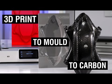 However, the researchers at LLNL were able to achieve the same material properties as two-thirds through a new 3D printing method.
To achieve this goal, LLNL created its own Direct Ink Printer (DIW) using its own carbon fiber composite "ink". The researchers also patented a method to cure extruded material in seconds, not hours. nine0003
They used the computational model shown in the video above to develop models for the flow of carbon fiber filaments in their inks. Julia Kanarska, Analyst, explains:
“We have developed a numerical code to simulate a non-Newtonian liquid polymer resin with a dispersion of carbon fibers. With this code, we can simulate the evolution of fiber orientation in 3D under different printing conditions. We've managed to find the optimal fiber length and optimal performance, but it's still a work in progress. Current efforts are to achieve even better fiber alignment by applying magnetic forces to stabilize them.” nine0003
Since the material is conductive, it allows the control of thermal channeling.