3D printed injection molding tool
The Truth About 3D Printed Injection Mold Tooling
Search
Search
Applications, Molding
Spoiler: 3D Printed Injection Molds aren't the same as steel tools
This post was written by Applications Engineer, Ben MacDonald
Injection molding has become the go-to manufacturing solution for plastic components. In 2019, the global injection molded plastics market size valued at $258.2B billion. Injection molded parts are used in a variety of industries and the application space is only expected to continue to grow. Even in automotive, plastics are trending to replace metals and alloys with injection molded plastics.
The economics behind injection molding parts is advantageous for molders, especially when the required part quantity is greater than 100,000. Though the dominant cost of injection molding is the high capital investment of a machined metal mold, once this mold is made, the costs of producing parts are minimal. Combine this with cycle times of 30 seconds or less and injection molding is a cost-effective solution for high-volume production. Even though the up-front cost of an injection mold is significant, molders can easily justify the expense based on the body of work that goes into completing a mold including:
- Maintaining extremely tight tolerances ensuring proper fit of a mold and its components
- Accounting for the shrinkage of molded parts upon cooling so they are geometrically accurate
- Controlling the surface finish of a mold, specific to the desired material for the specific part
Today, this is done with a hardened steel as it is the material of choice to withstand the intense requirements of a production run greater than 100,000 parts.
The Molders’ Dilemma
What happens when you aren’t producing hundreds of thousands of parts on a mold? With numerous industries (like electric vehicles) looking at low-volume production, how can molders justify the high cost of a tool when you are producing only hundreds of parts? Furthermore, because of the high cost of prototype tooling (sometimes called soft tooling or bridge tooling) designers find it impossible to rationalize properly prototyping parts.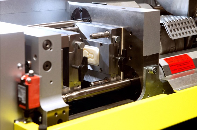 Rather than molding 10 iterations of a single part in their end-use plastic, designers are forced to take their best guess at which version will be the best for their specific application, relying on sub-par rapid prototyped parts in the interim for form, fit, and function assessment. After waiting 6-8 weeks for a tool, they either realize they selected the right design or, more often than not, have to accept the design being just good enough. In the worst case, the design is completely wrong wasting both time and money that was invested in the mold.
This is exactly where 3D printed injection molds step up to the plate. The ability to rapidly print and mold parts is game changing for part designers. 3D printed tooling exhibits faster lead times (1-2 days) at a fraction of the cost of machined soft tooling, making them a viable candidate for molders who are looking at the economics behind a tool that is only used for small volumes.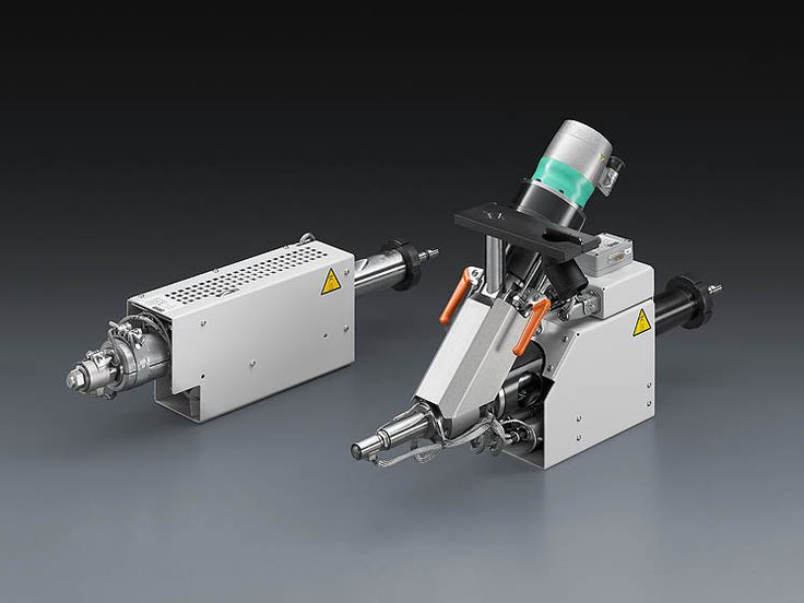 Additionally, 3D printed mold tools enable designers to print and mold multiple iterations of a part. This gives them the freedom to explore many more designs and confidence that their final design will be the right design. Using a 3D printed mold tool from Fortify gives part designers the flexibility to mold geometries in a variety of engineering-grade plastics so that their prototypes can match their final parts. Because Fortify’s tools are fiber-reinforced they are able to maintain their stiffness and withstand the high temperatures of injection molding.
Integrating 3D printed tools into your injection molding operation for prototyping and low-volume production starts with understanding the differences in the tools and how that affects how you design, machine, and run a tool.
What’s the Difference Between 3D Printed Injection Mold Tooling vs Metal Injection Molding?
The obvious fundamental difference between steel molds and printed molds is the material they are made out of.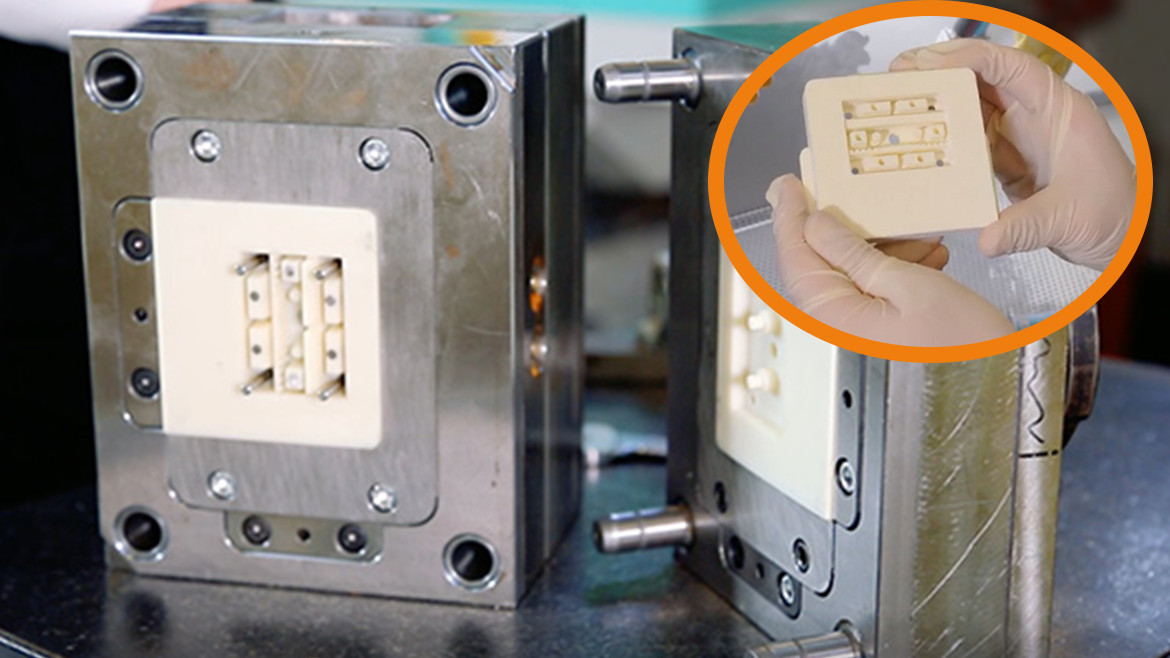 A good rule of thumb is to design 3D printed tools to be more “forgiving” than a steel tool. For instance:
- Shut off angle: In a steel tool, it is recommended to have an angle of at least 3 degrees when designing shut off features. Any less and you run the risk of the features wearing out or breaking too quickly. For a 3D printed tool instead of 3 degrees, 5 degrees is recommended
- Draft angle: Draft angles of features on steel tools are typically 1 or 2 degrees, and can go down to 0.5 degrees or less. 3D printed tools follow that same trend, except 3 degrees is recommended, and certain features are able to be molded with much less.
- Ejector pin: Determining the placement of ejector pins on a mold so a part doesn’t break during ejection is important. In steel tools this is pretty straightforward and usually minimizes the amount of ejector pins needed. In 3D printed tools, designs need to also consider small and delicate features, and have pins placed so that the parts won’t flex during ejection.
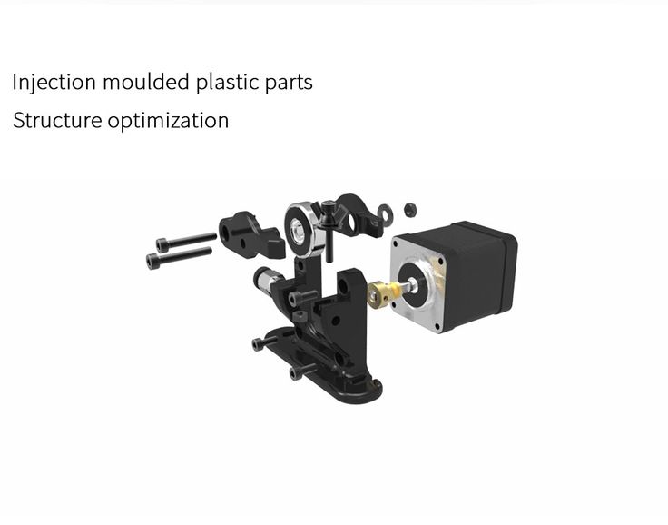 This can be accomplished by placing a pin next to a high aspect ratio extrusion or at the base of a rib rather than next to a rib. The great thing about adding in all of these ejector pins is that they provide excellent opportunities for ventilation.
 - Ventilation: 3D printed molds are unable to withstand the kind of pressures that steel molds can endure. One way to compensate for this is to add in more ventilation than there otherwise would be in a steel tool. This can take the form of surface vents, ejector pins, and vent holes to name a few. The goal with this ventilation is to always give the air in the cavity an easy path to escape so that the flow of the plastic is never restricted.
By understanding and accepting these design differences, molders can realize significant success when molding parts. Additionally, 3D printing molds can give designers much more freedom. If a designer wanted to iterate on two features within a complete mold, they don’t have to print multiple iterations of the mold.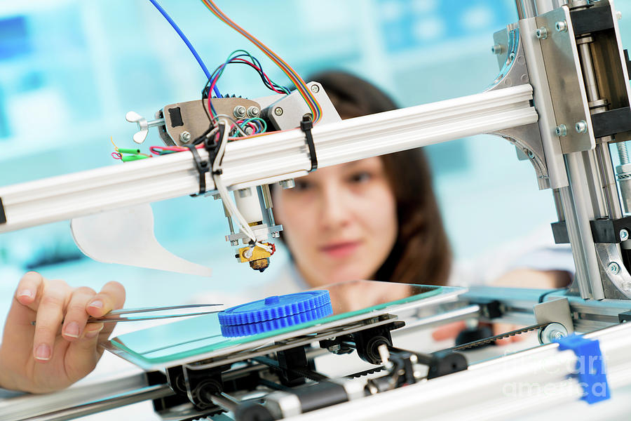 They can simply design the features as inserts for one common mold. Furthermore, fine details and complex geometries don’t cost extra to print (unlike EDM for traditional tools), and designers are able to add in detail that would significantly drive up the cost of a steel tool.
Improve Injection Mold Designs with Fortify 3D Printed Injection Molds
As 3D printed injection mold tooling continues to be adopted, it is important for both part and mold designers to learn how to best design for additive. A good design will drive success. There are plenty more tips on best practices for designing, machining, and running 3D printed injection mold tools. To learn more, download our guide Best Practices for Fortify Injection Mold Tools.
3D-printed molds vs. aluminum tooling
3D-printed molds, as seen here, have their place, although, in most cases, we recommend using 3D-printing for prototype or end-use parts but not for molds. Photo: DSM Somos
Industrial 3D printing has made a tremendous impact on the manufacturing world. Rapid prototypes are possible within days, material selection and advances continue to grow stronger, and parts with un-manufacturable designs have found their happy place. Recently, some companies have begun using this important technology to produce injection molds. Our advice? In most cases, use 3D printing for parts—prototype or end-use—but not for molds. Let us explain.
Molds made with thermoplastics-based 3D printing are kind of like the plastic storage sheds some of us put in our back yards. They’re a little cheaper than metal sheds. They go up quickly and are fine under light loads. Pile too much snow on them, however, and they’ll collapse like a house of cards.
Still, printed molds have their place, and some shops have had good success with them. Proponents argue that 3D printing produces molds up to 90 percent faster and 70 percent cheaper than using traditional mold-making processes. And while this may be true in some circumstances, it’s important to understand the pros and cons of printed plastic molds compared to those machined from metal.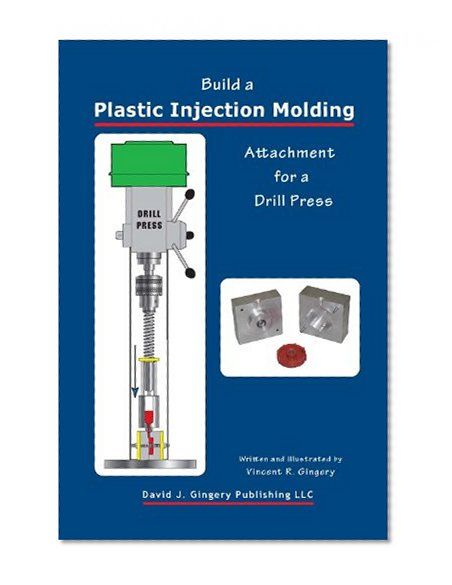
Quality is King
3D printing builds parts in layers. Because of this, printed parts can exhibit a stair-step effect on any angled surface or wall. Printed molds are no different, and require machining or sanding to remove these small, jagged edges. Holes smaller than 0.039 in. (1mm) must be drilled, larger holes reamed or bored, and threaded features tapped or milled. All of these secondary operations eliminate much of the “print-to-press” speed advantage associated with printed molds.
Whether using a single-cavity or multi-cavity mold, aluminum tooling is generally the preferred method for mold-making.
Size Matters
Part volumes are limited to 10 cubic inches (164 cm3), roughly the size of a grapefruit. And although modern additive machines have impressive accuracy, they cannot compete with the machining centers and EDM equipment at Protolabs, which routinely machine mold cavities to +/- 0.003 in. (0.076mm) and part volumes up to approximately 59 cubic inches, about six times larger than parts made with 3D printing.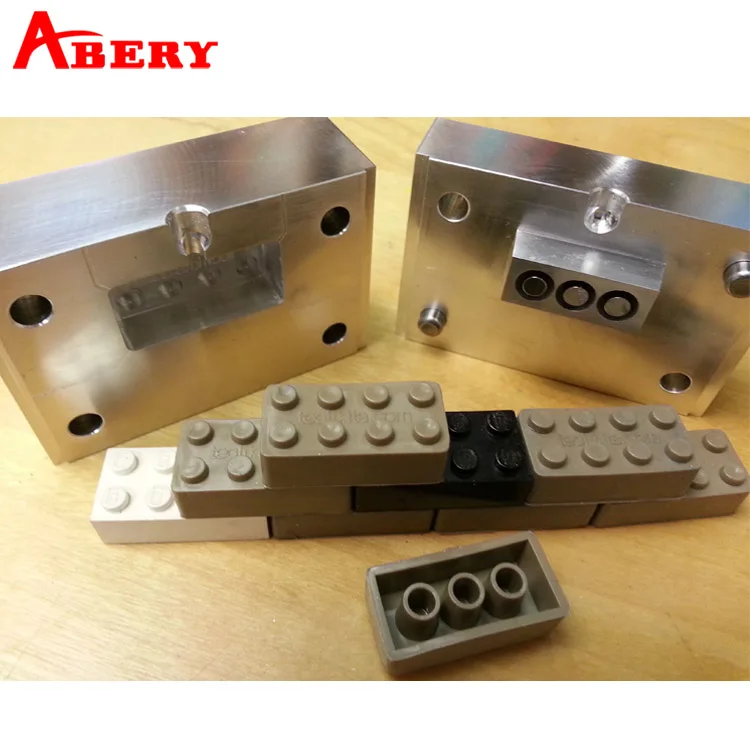
The Heat Is On
To make material flow properly, injection molding requires very high temperatures. Aluminum and steel molds are routinely subjected to temperatures 500°F (260°C) or greater, especially when processing high-temperature plastics such as PEEK and PEI (Ultem). Aluminum tools can easily produce many thousands of parts, and can also serve as bridge tooling until a production mold is available. Molds produced with stereolithography and similar 3D printing technologies use photoreactive resins, which are cured by ultraviolet light. These plastic molds, though relatively hard, break down fairly quickly when subjected to the demanding thermal cycles of injection molding. In fact, printed molds typically become ineffective within 100 shots of soft, hot plastic such as polyethylene or styrene, and may produce only a handful of parts from glass-filled polycarbonate and other tough thermoplastics.
Comparable Costs
One of the biggest draws of a printed mold is its low cost.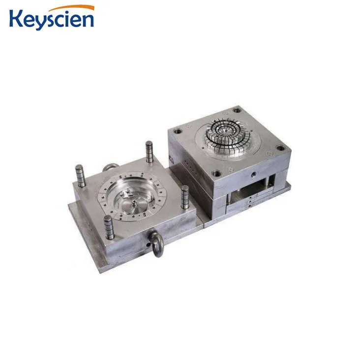 Aficionados point to production-grade machined tooling costing $20,000 or more, suggesting this as an apples-to-apples comparison with a $1,000 printed mold. It’s not a fair analogy though, at least not here at Protolabs. Cost estimates for printed molds are frequently “material only” and do not include labor for assembly and fitting, ejector systems, and miscellaneous hardware. Our aluminum molds start at around $1,500 and are ready to go. Need more parts? With 3D-printed molds, you’ll need to print, machine assemble, and test a new mold every 50 to 100 shots. Aluminum tooling has no such constraints, and often see service well past 10,000 shots, regardless of the plastic being used. Additionally, if you choose our on-demand manufacturing option for injection molding, mold life is unlimited, molds can be stored with us for three years of inactivity, and we offer single and multi-cavity mold options (see photo above).
Part Design
The principles and practices of conventional injection mold-making have been in use for more than a century, and are well understood in the industry.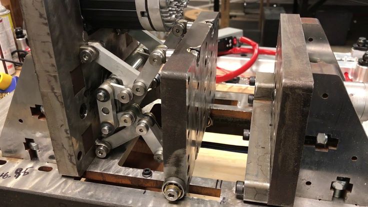 Printed molds are fairly new. For example, draft angles must be increased to 5 degrees or more, greatly exceeding that of most aluminum tooling requirements. Ejecting plastic parts from a plastic mold can be challenging, so greater attention must be paid to the placement and quantity of ejector pins. Plastic molds are somewhat flexible, especially at higher molding temperatures, making much thicker cavity walls and lower operating pressures the norm. Gate design is different as well. Tunnel and point gates should be avoided, while sprue, fan, and tab gates should be increased to 3 times their normal size. Polymer flow through the printed mold should be oriented in the same direction as 3D print lines, to avoid sticking and improve filling at lower injection pressures. Cooling systems can be used to improve mold longevity somewhat, but will not decrease the substantially longer cycle times seen with printed molds, as plastic tools do not dissipate heat nearly as well as ones made of aluminum or steel.
A Time and a Place
Despite the advantages of rapid injection molding with aluminum tools, there are times when printed molds make sense. For shops that have an idle 3D printing machine, and time available on their injection molding machine to work through the learning curve associated with printing molds, some might argue that equipment should be put to use. Of course, mold designers must understand how to build a functioning tool, or costly rework and rebuilding of molds will be needed. Support people and equipment are needed as well—machinists or toolmakers to sand the mold, fit the pins, bushings, and mounting hardware, and an injection molding machine operator available to dial in the shot size, temperature, and machine pressure, since these will be far different than the parameters he or she is used to with conventional tooling.
However, injection molds produced with 3D printing machines might be a viable alternative if:
- Very low quantities of relatively simple parts with large draft angles are needed.

- Your tool-and-die team is familiar with the design rules of molds made with 3D printing.
- People and machines are available to process and assemble the plastic tool.
For now, it’s probably better to use 3D printing technologies for what they do best: printing parts, not molds.
Upload a CAD model today to see if an aluminum injection mold is right for your next project.
technical study from a leader in the plastics industry
The French Industrial and Technical Center for Plastics and Composites - IPC, conducted a study evaluating the performance of injection molding using 3D printed molds. This article summarizes some of the findings, particularly those related to Formlabs 3D printers.
Injection molding is an economical and highly reproducible technology mass production of plastic parts with tight geometric tolerances. However, the high cost of traditional steel equipment makes it difficult to injection mold small batches of parts and can often be a barrier to new product introduction.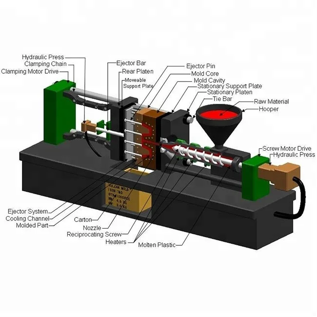 By using 3D printed injection molds, engineers, fabricators and product designers can lower their costs, reduce lead times and bring better products to market. 3D printed injection molds are a great option for those who want to develop functional prototypes from end-use materials, produce a series of identical pre-production samples, or even custom or limited-edition end-use models. nine0003
Checkpoints
The IPC study was divided into three phases:
1 . Comparison of 3D printing technologies: The first classification was based on the technical data of several manufacturers. The thermal and mechanical characteristics were evaluated, respectively, in terms of deformation heat resistance (HDT) and tensile modulus. To select the three most promising materials for each of the identified technologies, four types of control points were developed to highlight critical properties. Due to the high resolution and smooth surface of the 3D printable models, resin-based solutions have been recognized as the best material choice for injection molding molds.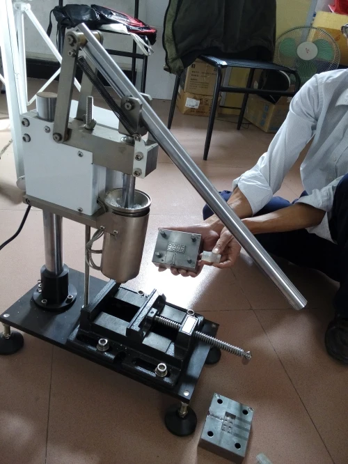 nine0003
In general, a similar range of dimensional variations is measured for all considered 3D printing technologies: from ± 0.02 mm to ± 0.05 mm for small parts and from ± 0.05 mm to ± 0.2 mm for large parts .
The standard accuracy of machined metal tools should be ± 0.02 mm. This accuracy is desirable for a good fit along the parting line and to prevent reflow. IPC offers two methods for optimizing the parting line of a 3D printed resin tool. nine0003
2 . Guidelines for material characterization, design, and 3D printing.
3 . Injection mold test: IPC performed two tests with different mold sets. In the first test, an "extreme test" scheme was used. Nearly a hundred polypropylene models were cast using a mono-material mold printed in High Temp Resin. The second test used a more complex "extreme test" scheme. Thousands of polypropylene models were molded using a mold of different materials: the core and mold inserts were printed from Rigid 10K Resin, and the frame was printed from Nylon 12 (Polyamide 12) using selective laser sintering technology. nineMold design from several materials with inserts (Fig. 2).
IPC has developed two sets of molds for casting two different complex patterns. Both sets were intended to optimize the quality of the parting line: nine0003
both halves of the tool must be positioned within a tolerance of ± 0.02 mm to ensure a correct fit.
1. Monomaterial mold printed in High Temp Resin.
It has a simple geometry with no inserts or additional moving parts, and includes texturing. To improve the parting line, it will be redesigned in the final stage.
Monomaterial mold STL file printed with High Temp Resin and loaded into PreForm software. Fixed side (left) and movable side (right). nine0040
2. Multi-material Mold: The fixed side of the mold is printed with Rigid 10K Resin and includes texturing. The moving side consists of one core and four inserts printed in Rigid 10K Resin,
as well as a frame printed in Nylon 12 (Polyamide 12) using selective laser sintering (SLS) technology.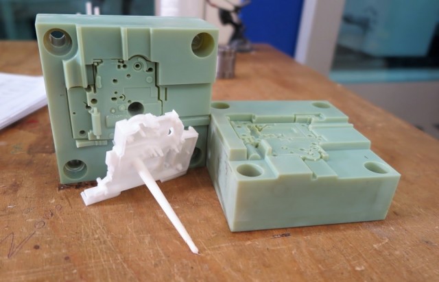 The soft frame is equipped with an insert to compensate for dimensional deviations from the parting line. Nylon 12 (Polyamide 12) is flexible enough to accommodate size variation during mold clamping. However, selective laser sintering should only be used to print the frame and not the entire plate, because it does not provide high enough resolution for the shaping surfaces, and the plate melts at high temperatures. nine0003
Multi-material STL files loaded into PreForm print preparation software: fixed side (left) and movable side, core and inserts (right) printed with Rigid 10K Resin.
This geometry is slightly more complex and is designed to test the stability of thin inlays. To simplify the assembly, the angle of inclination between the core and the frame is three degrees. The frame was made with a 0.05mm allowance for a better fit. nine0039
Nylon 12 (Polyamide 12) frame CAD design for multimaterial movable mold side.
CAD file of shapes, textures look the same with both tool sets. From left to right: (1) Large sphere with a radius of 1.82 mm and a height of 0.3 mm; a small sphere with a radius of 1.09 mm and a height of 0.3 mm. (2) Wood 0.25 mm high. (3) Pyramid with a side of 0.3 mm and a depth of 0.2 mm. (4) Leather 0.14 mm high.
Design manuals
After several revisions, the IPC recommends the following best practices:
- Plan an allowance for the printed form and process it to adjust the dimensions.
- Avoid small cores: parts with a smaller section may not withstand pressure and temperature. IPC recommends printing several inserts for thin protruding parts (they can be replaced in case of failure) or making small parts from metal. nine0094
- Making a structure larger than 400 mm can be a challenge. Since the parameters increase with size, it will be more difficult to match the shape.
- Increase pitch and overhang angles (10° to 20°) to avoid distortion.
- Do not integrate cooling channels into the mold design.
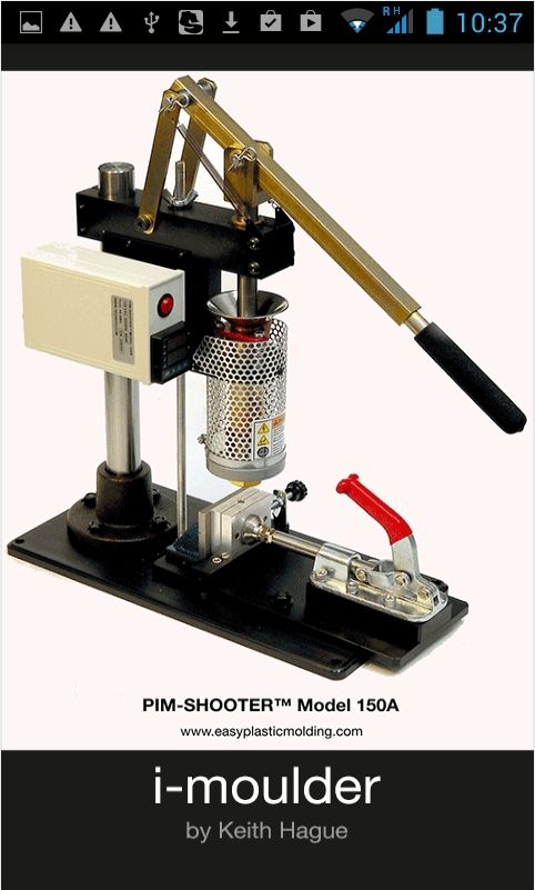 Heat transfer in plastic models is slower than in metal models, so the cooling channels will not have enough effect on temperature to compensate for the time spent designing this system. When complex materials or designs are used, regulation may be useful, but this is for further study. nine0094
3D mold printing
3D printing resin
Forms were printed on a Form 3 3D printer and post-processed on Form Wash and Form Cure devices. IPC printed two different sets of molds:
- High Temp Resin mold printed at 25 µm layer height was washed in isopropyl alcohol for six minutes, cured for 120 minutes at 80°C and thermal cured for three hours at 160° C. This material has a HDT of 238° C at 0.45 MPa, the highest among Formlabs polymers and one of the highest among polymers on the market. These characteristics allow it to withstand high injection molding temperatures with minimal cooling time. nine0094
- Form core and inserts in Rigid 10K Resin, printed at 50 µm layer height, rinsed twice in isopropyl alcohol for 10 minutes, cured for 60 minutes at 70°C, and thermal cured for 90 minutes at 125°C to achieve higher deformation heat resistance.
 This polymer is an industrial material with a high glass content - ideal for casting of a wide variety of geometric shapes and under different conditions of the injection molding process. Rigid 10K Resin has a deformation heat resistance of 218° C at 0.45 MPa and a tensile modulus of 10,000 MPa. These characteristics make this polymer a strong, extremely rigid and thermally stable molding material that retains its shape under pressure and at temperature for the manufacture of precise models. The mold frame was printed from Nylon 12 (Polyamide 12) using SLS selective laser sintering technology. nine0094
3D printing manual
After several revisions, IPC recommends the following best practices for 3D printing:
- Print with Rigid 10K Resin for extended plate life.
- Use a low layer height for better resolution: SLA 3D printing provides very fine texturing.
- Whenever possible, print the plate without supporting structures to achieve greater dimensional accuracy and avoid distortion.
 nine0094
 - Orient the mold so that there are no protrusions.
- Orient the mold so that there are no protrusions.
Mold printed with Rigid 10K Resin, fixed side on build platform
- If possible, print both halves aligned with the assembly direction. Possible size variations can improve the compatibility and quality of the parting line.
- After 3D printing the mold, machine it. In particular, adjust the parting line so that both halves of the mold match each other and do not melt. The diameter has a risk of warping, so holes may need to be drilled.
Rigid 10K Resin Mold Printed Textures
Scan Metrology
IPC scanned the plates to evaluate dimensional change immediately after printing and after final curing. These scanned images show less than ±0.05 mm deviation for over 75% of the details. nine0003
1. High Temp Resin. Scans of a 3D printed High Temp Resin mold: movable side (left) and fixed side (right).
2. Rigid 10K Resin. Scans of a 3D printed Rigid 10K Resin plate: movable side (left) and fixed side (right).
Injection molding
Mold Assembly
As mentioned above, it is recommended to process the 3D printed mold before assembly to ensure that critical dimensions are met. However, the multi-material mold did not need to be machined as the soft Nylon 12 (Polyamide 12) parting line is able to absorb dimensional changes. You can then add push pins or inserts. IPC recommends printing several inserts for thin models with protrusions that are at increased risk of breakage: in this case, they are easy to replace. Mold handling and assembly are operations that require care as 3D printed parts can break during processing. 3D printed molds should be placed in a metal die or master mold to withstand the pressure. nine0003
Form printed in Rigid 10K Resin and mounted in a metal matrix. Moving side with ejector pins (left) and fixed side (right).
Form printed in Rigid 10K Resin and mounted in a metal matrix. Movable side with ejector pins, inserts, SLS bezel (left) and fixed side (right).
Conditions of injection molding process
The team has cast thousands of models under the following injection molding conditions:
- Injection molding machine: industrial, ENGEL 150T
- Injection molding material: polypropylene (PP)
- Injection molding temperature: 200° C
- Casting pressure: 180 bar
- Mold clamping force: 125 kN
- Release agent: none nine0094
- Cooling system: none. The temperature was controlled by a thermal imaging camera and the cycle only started when the plate temperature was below 36°C.
- Ejection: automatic with ejection pins and robotic arm designed to move the part
- Cycle time: 150 sec.
results
IPC cast 90 polypropylene models in a mono-material mold printed in High Temp Resin. nine0003
Cast models were distinguished by high surface quality and detail. However, after 31 iterations, the mold began to crack, which affected the surface quality of the remaining cast models.
Model #31 (left) and Model #90 (right) molded in High Temp Resin
1000 polypropylene models with a multi-material mold printed with Rigid 10K Resin. nine0003
Cast models were distinguished by high surface quality and detail. There were light fusions after the first castings and small cracks around the core clamps after 900 castings. Lightening appeared at the place where the sprue was supplied.
Light fusion on last model (left) and small cracks after 900 castings on Rigid 10K Resin core.
Textures on finished models molded in multiple materials. nine0040
IPC recommends selecting Rigid 10K Resin to maintain shape durability.
This polymer is less brittle and exhibits better load strength than
High Temp Resin. The 3D printed mold should be processed to improve parting line accuracy and reduce flashover. Using a multi-material soft-framed mold is a great alternative solution for compensating for dimensional variations. IPC suggests that the molding process will be more difficult when dealing with viscous materials such as polycarbonate (PC), nine0003
as well as casting temperatures above 240° C.
IPC evaluated the possibility of using 3D printed injection molds in low volumes. With a mold core printed in Formlabs Rigid 10K Resin and a soft frame printed in Nylon 12 (Polyamide 12), thousands of polypropylene parts have been cast, reducing printing costs by 80-90% compared to using a metal mold.
Desktop 3D printing is a powerful solution for making injection molds quickly and inexpensively. It requires a limited amount of equipment, which reduces the time of the CNC and skilled operators and frees them up for other important tasks. Desktop 3D printing is easy to integrate into any injection molding workflow as it is easy to install, operate and maintain.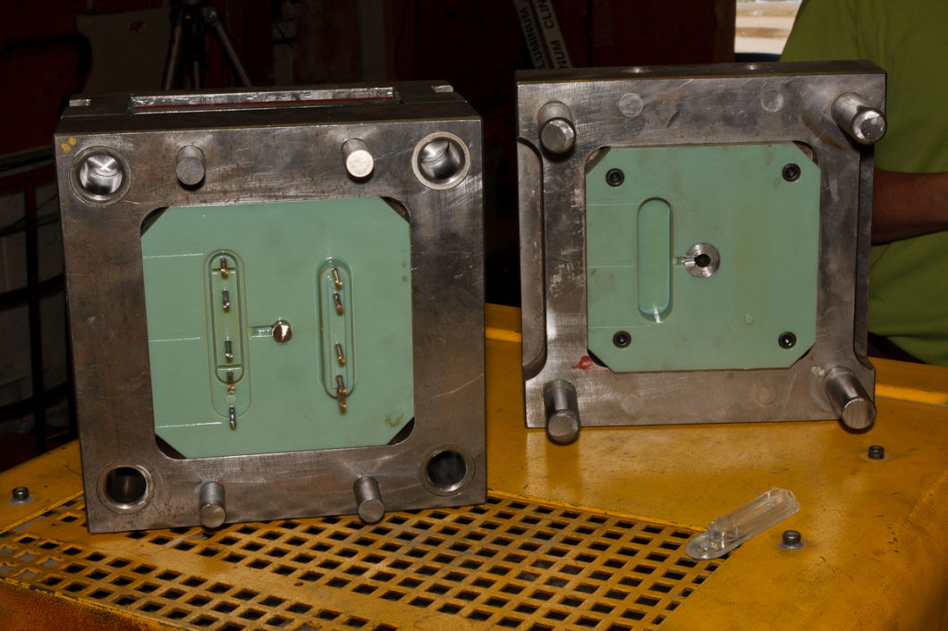 Manufacturers will benefit from the speed and flexibility of in-house 3D printing to create a mold and combine it with the power of industrial injection molding. nine0003
As a result, it will be possible to produce a series of products from conventional thermoplastics in a matter of days.
We will keep you updated with the latest news!
Your team iGo3D Russia :)
Our groups in social networks:
YouTube
VKontakte
3D printing applications: Injection Molding
Skip to Content Main
Accelerate product development, reduce costs and lead times, and bring better products to market by using 3D printing and small-scale injection molding in your manufacturing process.
Read white paperRequest a sample
Use 3D printed injection molds on desktop and industrial machines to efficiently and cost-effectively produce hundreds to thousands of functional prototypes, as well as prototyping or final models. nine0003
Molds created with Formlabs 3D printers have been validated for use on desktop and industrial molding machines with varying pressures, temperatures and materials.
View the molding conditions customers have used
A complete desktop ecosystem
You can easily start 3D printing injection molds yourself with a Formlabs 3D printer and desktop molding machine. Quickly test, validate and reproduce prototypes, create pre-production models from material that will be used in production, and produce small series of final models without the need for a lot of equipment and training. nine0003
A complete, easy-to-use Formlabs ecosystem can be integrated into any injection molding workflow. Save time and money on low-volume injection molding projects by taking advantage of 3D printing to quickly and cost-effectively produce hundreds to thousands of models from common thermoplastic material.
Read the Quick Start Guide
Step 1
Mold Design
Use conventional manufacturing design techniques to create 3D printed molds.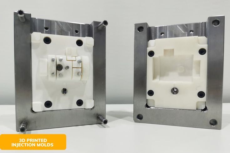 nine0003
Stage 2
Printing molds on the
Form 3 3D printer uses high performance materials such as Rigid 10K Resin to produce durable, smooth and detailed models.
Stage 3
Assembling the mold
Assembling 3D printed molds using a mold block increases their durability.
Stage 4
Mold closure
3D printed molds can be used on desktop and industrial molding machines. nine0003
Stage 5
Injection Molding
Molds created with Formlabs 3D printers have been validated for use in a variety of process conditions.
Stage 6
Cooling
The cooling process, which usually takes a long time for plastic molds, can be accelerated using compressed air.
Step 7
Removing the model from the mold
You can add ejector pins to automate the process of removing the model from the mold. nine0003
Formlabs' ecosystem of affordable 3D printers and high-performance materials produces durable, smooth, detailed injection molds that can produce hundreds to thousands of models in difficult casting conditions.