3D printed co2 gun
Free STL file Single Action CO2 Airgun Revolver・3D print object to download・Cults
Iterating on my blowgun designs, I decided to tackle a classic mechanism: The Single Action Revolver.
This is a six shot, break action revolving cylinder gun that shoots the same 1 inch blow darts used in my Bolt Action Rifle and uses the same shells. Load six shells into the cylinder and screw in a CO2 cartridge, then pull the trigger to fire. Cocking the hammer back and releasing rotates the cylinder into the next position, readying for fire again.
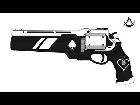
This design was inspired by the Webley Revolver and has a similar form factor.
https://www.youtube.com/watch?v=BSjc8RC7HmA
DISCLAIMER: By downloading these files, you agree that I shall not be liable for any damage, injury or harm resulting directly or indirectly from the use of these files or instructions. Check your local laws and always be safe and aware when operating these mechanical toys and enjoy!
Required Parts
Rigid Tube (10mm Inner Dia, 14mm Outer Dia)
Flexible tubing (4. 25mm Inner Dia, 5.75mm Outer Dia). The inner dia is less critical than the outer dia, which should be between 5.5mm and 6mm.
Mini blow darts
16g or 20g threaded CO2 canisters
CO2 Tire Inflator
M4 screws
M3 Screws
M2 Screws
7/32" x 11/16" Compression spring
Small Rubber bands
Printed Parts List
ShellCylinder
RearFrame
BarrelFrame
BarrelShroudExtender (Optional)
FrontSightBarrelShroud
FrontSight
LockBar
BarrelLatch
NozzleSlider
Hammer_Split
HammerPawl
CylinderRatchet
RearFrameLockBarPlate
CylinderAxle
CylinderSpringPin
CylinderIndexPin
TriggerGuard_Split
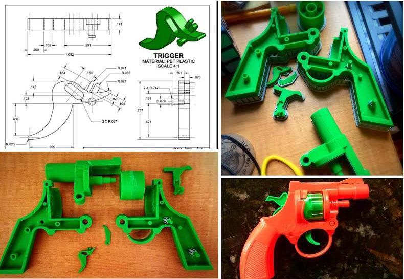
Trigger
GripFrame_R
GripFrame_L
GripPlate_L
GripPlate_R
DartShell [x6]
Assembly Guide
Shell Printing
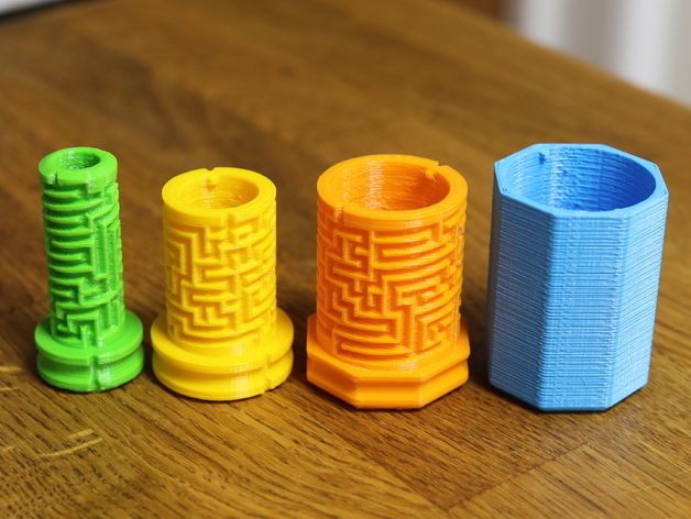
Ive included two variants of the shell depending on your printer's tolerance / filament.
One has a 10.1mm inner diameter for a tight fit with the darts, and the other has a 10.3mm inner diameter for a somewhat looser fit. The darts should be pretty tight when inserted such that they dont fall out when tipped upsidedown, but not so tight that they cant be pushed out. Try printing one of each shell to see which works best for you. You can do finer adjustments to the tolerance by putting some scotch tape or masking tape on the inside of the shell wall.
Print the shells with the flat bottom on the build plate at 0.3mm layer height. You might want to add a 2 or 3 mm brim to keep them attached to the build plate. If so, ensure you cut off the brim with a knife so there is no extra flashing as this will prevent them from being properly seated in the cylinder.
Rear Frame Assembly
Gather the following parts: RearFrame, Hammer_Split, HammerPawl, CylinderIndexPin, RearFrameCylinderLockPlate, NozzleSlider, RearFrameLockBarPlate, PawlSpring, BarrelLatch, M2x20mm screw, M2x8mm screw, M3x30mm screw, M2x6mm screw.
See the image for help with this section.
First, take the CylinderIndexPin and place it into the narrow channel on the bottom of the RearFrame.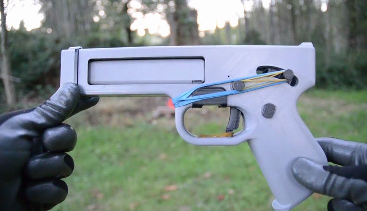 Align the hole in the front of the pin with the hole in the RearFrame and secure with the M2x20mm screw. It should be able to rotate freely around the screw, if not, sand down the pin.
Slide the RearFrameLockBarPlate onto the rail on the top of the RearFrame and glue into place.
Next, take the two halves of Hammer_Split and use some super glue to glue them together. Make sure you apply glue to the thin arc at the bottom of the hammer.
Next, take the HammerPawl and align its hole with the left side of the Hammer and use the M2x8 screw to secure it to the hammer from the right side of the hammer. It shouldnt be too tight as it must rotate around the screw.
Place the NozzleSlider into the cylindrical hole on the RearFrame, then place the Hammer and Pawl assembly into the slot, such that the tab on the top of the hammer is in the cutout on the NozzleSlider.
Place the BarrelLatch around the RearFrame and line up the larger hole with the Hammer Axis hole, then use the M3x30 screw to connect the BarrelLatch, RearFrame and Hammer together, going all the way through to the other side.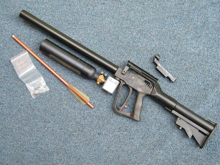 You should be able to rock the hammer back and forth, which should push the NozzleSlider in and out.
Screw the M2x6 screw into the small hole on the left side of the BarrelLatch. Well use this screw later to connect a rubber band so that the latch springs back into place when closed.
Now, take the PawlSpring and apply some glue to the bottom and sides of the rectangular plate on it. Slide it in next to the left side of the hammer, behind the Pawl and hook the curved spring part around the hammer axis screw and press it into place such that the bottom of the rectangular plate is flush with the bottom of the slot on the RearFrame, and the back face of the rectangular plate is flush with the back face of the RearFrame. Let the glue dry and ensure that the hammer and pawl still rotate freely. The springs purpose is to push the pawl forward when engaging with the CylinderRatchet.
Take the RearFrameCylLockPlate and glue it into the shallow circular cutout on the front of the RearFrame, ensuring the cut side faces the pawl.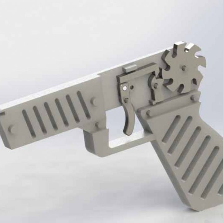
Finally, take your small rubber band and loop it around the hooks on the RearFrameLockBarPlate and stretch it around the semicircular notch on the hammer. This should allow the hammer to return after being cocked back.
Barrel Frame Assembly
Gather the Following Parts: BarrelFrame, CylinderAxle, LockBar, CylinderSpringPin, BarrelShroudExtender, FrontSight, FrontSightBarrelShroud, rigid tube, M4x20 screw and nut.
Note: The default length of the barrel tube is 130mm but you can make it longer or shorter if you want. To increase the length, just scale up the BarrelShroudExtender along its length axis. To make it shorter, you can scale down the BarrelShroudExtender or omit it entirely.
Cut your rigid tube down to 130mm. Push it through the hole in the BarrelFrame so that one end of the tube is flush with the rear of the BarrelFrame.
Slide the BarrelShroudExtender over the tube and press it onto the BarrelFrame such that the small notch lines up. You can glue it into place now if desired.
Slide the FrontSight into the rail on the FrontSightBarrelShroud. It should have a tight fit, but if not, you can glue it into place. Feel free to make your own front sight and exchange it!
Slide the FrontSightBarrelShroud over the tube and press it onto the BarrelShroudExtender such that the notches align. Again, feel free to glue it together at this point.
Next, take the LockBar and slide it onto the rail on the top of the BarrelFrame. Apply some glue and slide it all the way back.
Finally, take the CylinderAxle and place your compression spring into the hole on the axle. Place the CylinderSpringPin over the spring such that the spring is inside the small hole on the CylinderSpringPin. You can then place the CylinderAxle into the smaller hole under the barrel on the BarrelFrame and optionally glue into place.
You can now connect the Barrel assembly to the RearFrame assembly via the M4x20 screw going through the pivot on both assemblies. Secure with the nut and ensure they can rotate freely.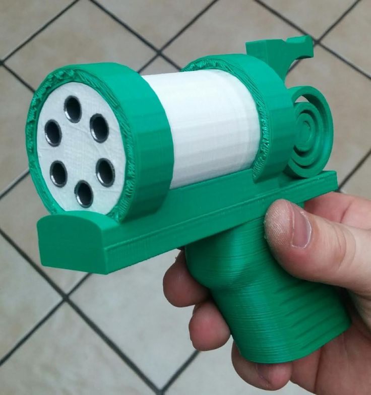
Cylinder Assembly
This part is nice and simple: Just take the ShellCylinder and CylinderRatchet and glue the Ratchet into the hexagonal slot on the top of the ShellCylinder. You can then place the Cylinder onto the CylinderAxle. Closing the Barrel should push the CylinderSpringPin back until fully closed, where the SpringPin should snap into the hole on the RearFrame's CylinderLockPlate. Meanwhile, the BarrelLatch should be pushed open by the LockBar.
Test out the hammer mechanism and ensure that it cycles the cylinder when cocked.
It might not work perfectly without shells in the cylinder as the NozzleSlider helps to align the cylinder by pressing into the back of the shells.
Grip Assembly
Gather the following parts: GripFrame_L, GripFrame_R, GripPlate_L, GripPlate_R, Trigger, TriggerGuard, Tire Inflator, M4x20 screw, 2 M4x30 screws, M3x20 screw, TubeValveCoupler, flexible tubing.
Sand down the inner faces of GripFrame_L and R so that you can place them together without gaps.
Place the tire inflator into the cylindrical channel in GripHalf_R such that the button is protruding out of the forward hole in the frame and the nozzle end is pointing towards the rear of the grip frame.
Place GripFrame_L on top to enclose the tire inflator. Attach the RearFrame to the GripFrame such that the small bracket extending from the bottom of RearFrame is inserted into the channel on GripFrame near the trigger area. Use an M4x20 screw through the left side of the grip frame to connect it to the RearFrame.
Place the Trigger into the slot of GripFrame and use an M3x20 screw through the left side of GripFrame to connect the trigger in place. You should be able to pull the trigger to depress the Tire inflator's button.
Use a small rubber band to connect that screw head to the small M2 screw protruding from the side of the BarrelLatch so that the latch will spring closed when the barrel breech is closed.
Take the two halves of the TriggerGuard and glue them together.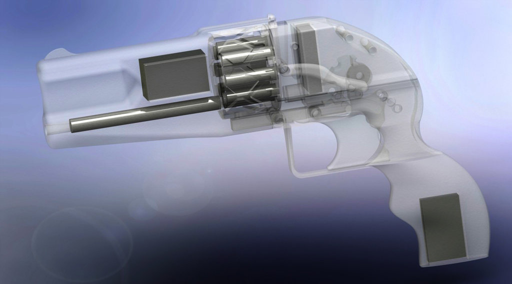 You can then slide it into the rail on the front of GripFrame and glue into place.
Now insert the TubeValveCoupler into the nozzle of the tire inflator. You might need to use some hot glue to seal it. Insert the TubeValveCoupler into the flexible tubing and use some glue to seal it.
Cut the tube down to a reasonable length and insert the other end into the NozzleSlider so the tube goes all the way to the tip of the NozzleSlider.
Finally, place the two GripPlates and place onto either side of the GripFrame. Use the two M4x30 screws and nuts to secure them together.
Congrats, youre done! Just screw in a 20g CO2 cartridge into the bottom of the grip, load up some shells and start firing!
Speed Loader Assembly
Ive included files for a "speed loader" which holds 6 shells which can be quickly dropped into the revolver cylinder with the push of a button. Youll need the following parts:
SpeedLoader_Body
SpeedLoader_BodyCap
SpeedLoader_Plunger
SpeedLoader_PlungerCap
SpeedLoader_PlungerStopPlate
SpeedLoader_RimTab [x6]
M3x14 screw
9/32" x 1/2" Compression Spring
Some 1. 75mm filament
Take the Body and place the spring into the central shaft. Place the Plunger, withthe hole in the shaft facing upwards, into the central shaft on top of the spring.
Prepare 6 of the RimTabs by pushing a peice of filament through the hole and cutting it such that there is a bit less than 2mm of filament protruding from either side of the RimTab.
Drop each RimTab into the rectangular slots of the Body such that the pointed end is upwards and the angled tip points towards the shell cylinders.
Meanwhile, glue the PlungerStopPlate to the top of the BodyCap such that the holes are aligned.
Now for the slightly hard part: Slightly depress the plunger and use a toothpick or tweezers to rotate each RimTab such that the thin rounded tab is inside the Plunger's notch cutout. Once all six tabs are aligned, you can fully depress the plunger to hold them in place.
With the plunger held down, place the BodyCap on top of the Body, using the six alignment tabs to help align it.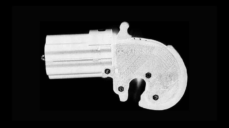 Once its in place, you can release the plunger and it should be pushed upwards by the spring and be stopped by the StopPlate.
Finally, take the PlungerCap and screw the M3x14 into the top face until the screw starts to protrude from the narrow end. Insert the narrow end into the BodyCap's central hole and screw the PlungerCap to the Plunger.
You should now be able to press the PlungerCap downwards to rotate all of the RimTabs to the open position, and have it spring back up when you let go.
Simple insert six shells into the SpeedLoader and press all the way back to have the RimTabs lock the shell rims in place. Push the plunger down to have all six shells drop!
Free STL file Repeating CO2 Blow Gun Pistol・3D printer design to download・Cults
Presenting my latest invention: The Repeating BlowGun Pistol.
Thats right, its a magazine fed CO2 powered pistol that shoots frickin blow darts. Its reloaded via lever action and can be operated one handed. The magazine holds 6 darts and with a bit of practice, you can load and fire at a rate of around 60 rounds per minute.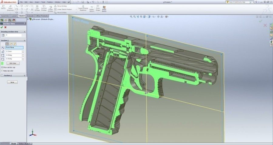
See it in action here
Unlike some of my other projects, this one relies heavily on specific parts that youll need to purchase. All of these parts are fairly inexpensive and available on Amazon. They are listed below. One important note is that I specifically modeled the pistol's grip to fit the exact CO2 bike pump specified. Theres no guarantee it will fit similar Bike pumps as I took measurements from the exact one I have.
DISCLAIMER: By downloading these files, you agree that I shall not be liable for any damage, injury or harm resulting directly or indirectly from the use of these files or instructions. Always be safe and aware when operating these mechanical toys and enjoy!
Required Parts
CO2 Bike Pump
Rigid Tube (10mm Inner Dia, 14mm Outer Dia)
Flexible tubing (4.25mm Inner Dia, 5.75mm Outer Dia)
Mini blow darts
16g or 20g threaded CO2 canisters
Neodymium cylinder magnets (5mm Dia, 3mm Height) [x4]
M4x30 screws [x2]
M4x20 screws [x2]
M4x10 screws [x4]
M3x30 screws [x2]
M3x20 screws [x5]
M3x12 [x2]
M3x8 screws [x7]
M2x12 screws and nuts [x3]
Small rubber bands
Assembly Guide
Magazine Assembly
Gather all of the magazine parts contained in the MagazineAssembly file, along with three M2x12 screws and nuts and two of the magnets.
Sand down the inner faces of the Magazine halves so that they can connect to eachother without gaps.
Take the MagazineExtractorArm_Left and the left side of the Magazine. Insert the thin end of the extractor arm into the slot on magazine. You should be able to click the arm into place so that it slides back and forth within the slot. Do the same for the right side.
Next, connect the two magazine halves together with the M2 screws and tighten. Ensure you can place darts into the magazine and have them move freely.
Now take the MagazineMagnetTab and insert the two magnets into the holes. Ensure the poloarity of the magnets is the same so that they both point in the same direction. Depending on your printer's tolerance, the magnets will either need to be pushed into the holes with some force and be held securely, or if the fit is looser, you might need to apply some glue to keep them in place.
Finally, glue the MagazineMagnetTab to the front bottom of the Magazine such that the magnets point downwards.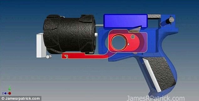
Barrel Assembly
Gather the following parts: BarrelBottom, BarrelTop, SliderBolt, BoltActuatorLeverMount_Right and Left, flexible tubing, two magnets and M3 screws.
Take the flexible tubing and push one end of it into the rear of the SliderBolt until it is flush with the end of the nozzle on the front of the slider bolt. Place the SliderBolt with the cylinder facing down into the channel on BarrelBottom. Ensure the larger end of the channel on BarrelBottom points in the same direction as the nozzle end of the slider bolt.
Insert the two magnets into the cylindrical holes on the top of BarrelTop and ensure they are aligned such that they will attract the two magnets in the Magazine tab.
Next, place the BarrelTop onto BarrelBottom such that the rails on BarrelTop enclose the SliderBolt, which should move freely back and forth. Secure the BarrelTop to BarrelBottom with 2 M3x20 screws using the front most pair of holes.
Insert 2 M3x30 screws through the rear pair of holes on BarrelTop and screw them in until the end of the screw is flush with the bottom of BarrelBottom.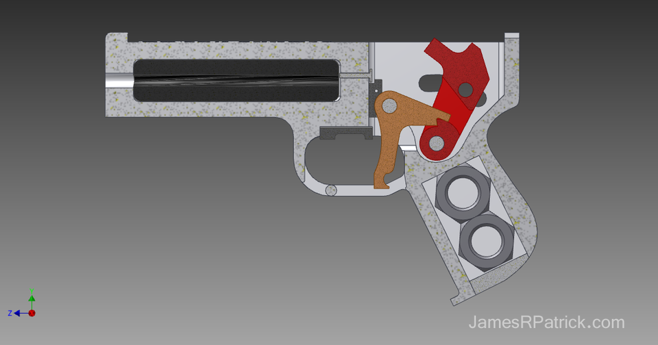
Take the ActuatorLeverArmMount_Left and right and align their rear most holes with the M3x30 screws, then finish screwing them in until the ActuatorLeverArmMounts are connected. Fully secure them by screwing 2 M3x12 screws into their front most holes, connecting them to BarrelBottom.
Now, take the rigid tube (14mm OD, 10mm ID) and cut it to your desired length. It should be at least 10cm in length. A longer tube results in a bit more power and accuracy.
Insert the tube into the front hole of the barrel assembly. It should be as tight as possible.
If its loose, wrap some masking tape around the tube and try again. Its also helpful to put a bit of hot glue on the rim of the tube before inserting to create an airtight seal with the Barrel assembly.
Finally, locate the 4 holes (two on either side of BarrelTop) and screw in the M3x8 screws. They shouldnt go all the way into the holes, but should stick out a bit. We will use these to hook the rubber bands around in a later step.
Optional Step: Attach the magazine to the BarrelTop's magnets. The MagazineMagnetTab should be flush with the front of BarrelTop. Take the MagAttachKey parts and glue them to BarrelTop such that their small round tabs fit into the cutouts on the MagazineMagnetTab. The MagAttachKey is there to prevent the magazine from sliding forward and backwards when attached. Ive found that this occasionally happens depending on the quality of the print, so only do this if you find it necessary. As a consequence, these parts will cover the front screw holes on BarrelTop, so if you want to retain access to them, unscrew them first and screw them back in from the bottom instead.
Bolt Actuator Assembly
Gather the following parts: BoltActuatorLever (x2), BoltActuatorTriggerCoupler, BoltActuatorTrigger_Short, M3 and M4 screws.
First, move the SliderBolt about halfway along its slide distance such that the pegs coming out of the side are in line with the hole on the ActuatorLeverMount's curved arm.
Place the long slot on the BoltActuatorLever over the peg, then align the large hole on the opposite side of the lever with the hole on the ActuatorLeverMount's curved arm. Secure it with an M4x10 screw. Repeat for the other side.
Next, take the BoltActuatorTriggerCoupler and place it between the two ActuatorLevers, aligning the middle hole/slot of the ActuatorLevers with the T shaped cylinder of the Coupler. Secure it in place on either side with an M3x12 screw. It shouldnt be too tight as we want the lever and coupler to be able to rotate.
Take the BoltActuatorTrigger and secure the top most hole to the rear holes on the side of the mount on each side with M4x10 screws. Connect the Coupler to the trigger's lower hole with an M3x8 screw.
Use two small rubber bands to connect the pegs of the SliderBolt with the protruding screws on the side of BarrelTop. You should now be able to pull the ActuatorTrigger to move the SliderBolt all the way back, and release it to let the SliderBolt return forward.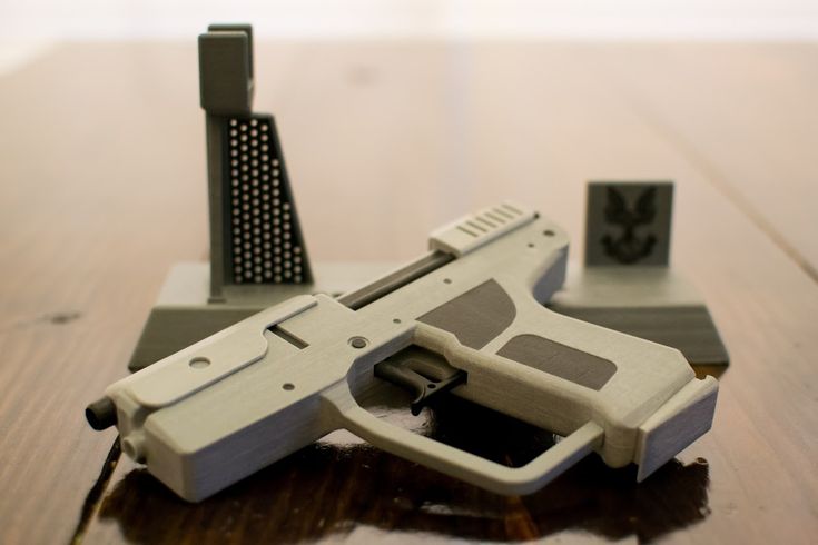 Ensure the motion is smooth and loosen any screws if necessary.
Now take the MagSlider and slide it onto BarrelTop from the rear such that the angled rails fit into the channels on the MagSlider. Using the other two small rubber bands, loop them around the hooks on the MagSlider and connect them to the other protruding screws on the side of BarrelTop. Ensure that the mag slider can move freely when pushed by the SliderBolt.
Grip Assembly
Gather the following parts: Grip halves, CO2 bike pump, TubeValveCoupler, MainTrigger, M4 and M3 screws.
Start by disassembling the Bike pump. Youll need to pry off the plastic shell that covers the top. You can do this by gently inserting a flat head screw driver under the lip and lifting it over the small pin which keeps it in place. Do this for the other side as well and the shell should pop off. Next, remove the green trigger by prying it off of the two angled pegs at its hinge. Once these have been removed, you can proceed to screw the TubeValveCoupler's larger end into the nozzle end of the Bike pump.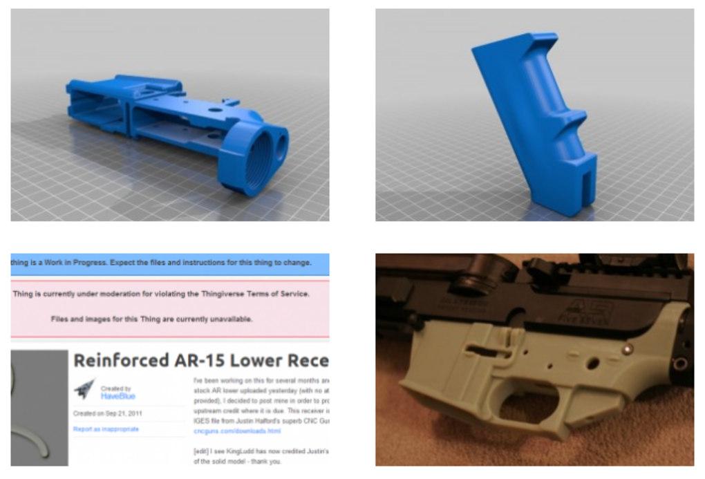
Take the two Grip halves and place them together. The rectangular portion on the rear has two small holes that the small pins on the Bike pump should fit into. Once the pump is enclosed by the grip halves, screw them together with the two M4x20 screws and nuts.
Next, place the MainTrigger into the slot in the grip and insert the M3x30 screw through the hole in the Grip and through the trigger. Try pulling the trigger, it should depress the small green button on the top of the Bike pump, which releases the gas.
Now, use two M4x30 screws to secure the grip to the rear end of BarrelBottom
Finally, connect the flexible tubing from the SliderBolt to the TubeValveCoupler. Ensure that its long enough so that when you cock the BoltActuatorLever, the tube doesnt have kinks in it and there isnt too much resistance. Once in place, either glue it to the tube coupler or wrap some tape around it to keep it secure.
Congrats! Youre done :) Just load up a magazine and load the BikePump with a CO2 canister.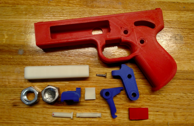 I find that 20g cartridges last longer and give more power than 16g cartridges.
To improve performance, ensure that the flexible tube isnt too long and has a tight seal. Also try adding hot glue to the rim of the Barrel tube then pressing it in to the BarrelTop/Bottom assembly to reduce leakage.
Most parts can be printed at 0.3mm for speed but some require 0.2mm resolution or finer. Everything can be printed at 20% infill unless otherwise specified.
Here are the print specifications for the various parts
MagazineAssembly / Magazine parts: Must be printed at 0.2mm or 0.1mm. The single DartMagazine part must be split, but I included the split version in the combined MagazineAssembly part.
BarrelBottom and BarrelTop: Can be printed at 0.3mm or finer.
MagSlider: Better if printed at 0.2mm but can be printed at 0.3mm. Might require some sanding around the rails so it slides smoothly against the rails on BarrelTop.
SliderBolt: 0.3mm or finer. Print upright so that the hole points upward.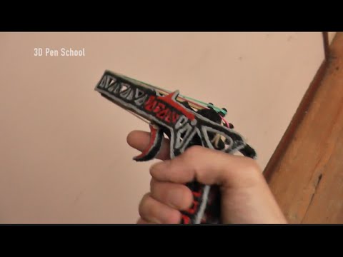
BoltActuatorLever, BoltActuatorLeverMounts, BoltActuatorTrigger and BoltActuatorTriggerCoupler: Can be printed at 0.3mm or finer. Recommend 50% infill for the BoltActuatorTrigger but 20% should be okay. BoltActuatorTrigger should be split down the middle for supportless printing, the split file is included.
MainTrigger: 0.3mm or finer, Recommend 50% infill.
Grip halves: 0.3mm or finer, can print with the outer sides on the build plate without support, but the rounded edges might have some issues. You can print with support for these edges to improve aesthetics. Alternatively, you can print with the inner faces on the build plate but youll need supports for the internal cavities and this will significantly increase print time.
is it possible to print pneumatic and firearms
Is it possible to make a gun on a 3D printer and is it legal?
Today's 3D printers offer enormous possibilities. They can print products of almost any complexity. Until quite recently, it was difficult to even imagine that a plastic weapon could shoot. However, it is already possible to make a pistol on a 3D printer, which, although not reliable, still fires live ammunition.
Can firearms be 3D printed?
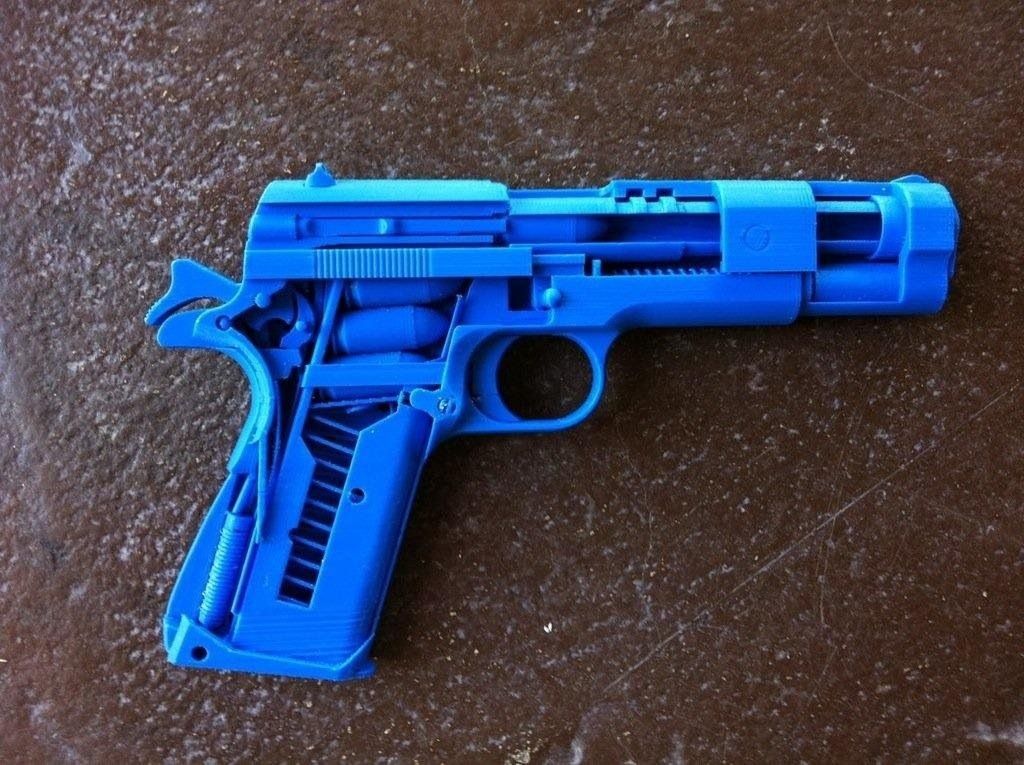
Back in 2013, a young American gun fighter proved that plastic guns could be 3D printed. He was the first in the world to make a pistol in this way, in which only the striker was made separately from metal. All other parts were printed on an FDM printer.
Today's 3D printers are capable of printing any CAD model, and these models of firearms have been available for over 10 years. If in previous years their printing required professional skills, now almost any user can master them. With a 3D printer and a finished model, it became quite possible to print a gun. Another thing is that such "creativity" is punishable by the laws of most countries.
The evolution of 3D printed weapons
Despite all the prohibitions and restrictions, the evolution of 3D printed firearms is moving at a great speed. The beginning was laid by the single-shot plastic pistol Liberator by American K. Wilson, which appeared in 2013. It had a simple design and was chambered for 380 ACP. Already after 10-12 shots, this weapon became unusable. However, the very possibility of printing firearms served as an impetus for the development of the idea. The author of the first pistol himself founded the Defense Distributed company, which began to actively improve the technology.
One of the ways to increase the durability of weapons was to increase the number of their barrels. At the beginning of 2014, the Japanese Y. Imura makes a 38 caliber Zig Zag pistol. He was able to fire up to 6 shots non-stop. The author of the weapon was recognized as a criminal and convicted.
The next step was the production of a six-shot revolver by J. Patrick in 2015. The PM522 Washbear has been shown in action on YouTube. The weapon was noticeably safer for the shooter compared to previous versions, but still allowed to fire only a few dozen rounds.
The first semi-automatic pistol for a 9 mm bullet appeared in 2016 under the name Shuty-MP1. It was developed by a handicraft gunsmith who hid under the pseudonym Derwood. It wasn't exactly a plastic weapon. The author used some metal parts from factory pistols - a barrel, a firing pin, a bolt and several springs. This made it possible to ensure a rate of fire of more than 46 rounds / min. However, when changing the store, the plastic case had to be cooled. In 2017, the same master proposed an improved model - Shuty AP-9.
The main contribution to the development of 3D printed weapons technology was made by Defense Distributed, which united a group of like-minded activists. First, these enthusiasts won legal proceedings in the United States and obtained permission to 3D-print weapons, which greatly expanded their capabilities. Secondly, they were able to set up a professional business with product testing and quality control. As a result, in 2018–19 they developed numerous models of a variety of firearms - from pistols to carbines. They posted over 30 files for printing original gun parts. Most of them were plastic, and the metal parts were not made from purchased, ready-made elements, but from simple metal profiles (tubes, strips, etc.), which are sold in ordinary hardware stores. This made it possible to exclude the use of parts patented by gunsmiths.
At the moment, the semi-automatic carbine FGC-9, developed on the basis of the Shuty AP-9, has become the pinnacle of "creativity" of Defense Distributed. At the same time, there is not a single factory part in it. The barrel for the 9 mm cartridge is made of steel pipe using electrochemical processing.
Where can I get drawings and what should I look for?
Gun manufacturing bans make it much harder to get blueprints and models of guns for 3D printing. The right to free placement of information was achieved only by Defense Distributed. Their website provides free access to drawings, models and technologies. Other information can be found on the Internet, but they are usually illegal.
When choosing a model, pay attention to the following information:
- material used;
- cartridge for which the model is designed;
- number of cartridges in the magazine, rate of fire;
- operating time before failure.
It is important to clarify which metal parts will need to be purchased separately, in addition to plastic for printing on a printer.
What does the law say in different countries?
The only country where firearms can be 3D printed is the United States. Gun Control Act 19 applies here68, giving Americans the right to make weapons, but only for personal use. Only one limitation is put forward: it must be determined by metal detectors, that is, it must have a metal element. In virtually all other countries, homemade manufacture and repair of weapons for any purpose is prohibited by law. In Russia, printing it on a 3D printer falls under the Criminal Code of the Russian Federation and is punishable by imprisonment.
Should we be afraid of plastic weapons?
The question of how dangerous a weapon printed on a printer is becoming increasingly important. Despite all the prohibitions, it is extremely difficult to control the spread of technology around the world. The availability of 3D printers and the increase in their functionality make it possible to master the production of plastic guns at home. How dangerous is such a weapon?
Most experts agree that currently printed weapons are more of an interesting toy. It is quite expensive and is designed to carry out only a few dozen shots. Moreover, such pistols are quite dangerous for the shooter himself with live ammunition, because they can explode in their hands.
However, the danger cannot be underestimated. It is easier and cheaper for a "serious" criminal to buy illegal military weapons than to make them on a printer. At the same time, there may be "enthusiasts" who, for their own interest, can make a pistol and try it out in action.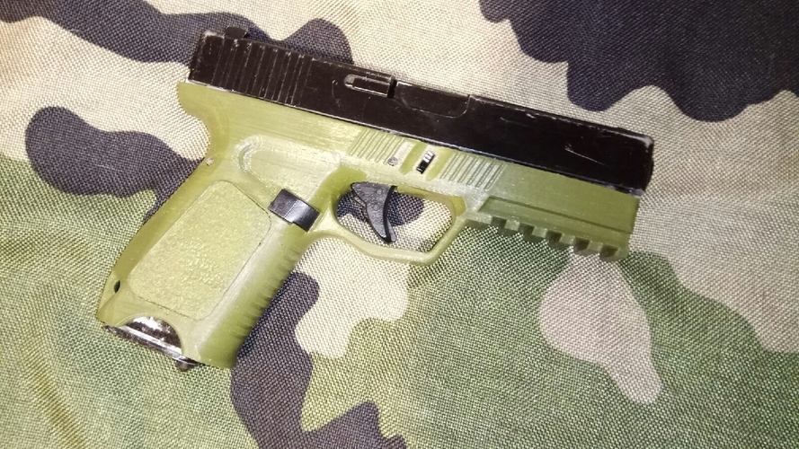 Such inadequate people represent an undoubted danger. In addition, the temptation is great for terrorists. Metal detectors do not detect a plastic gun, which means that it is easier to carry it, for example, on an airplane.
Important! Plastic weapons have a very small resource. At the same time, sometimes just one shot is enough to kill a person.
3D printed firearms have the following advantages:
- the ability to make military weapons at home;
- light weight;
- availability of materials;
- Ability to copy famous weapon models.
Always remember that there are significant disadvantages:
- illegal production;
- high cost of weapons;
- very small resource and limited rate of fire;
- danger to the shooter himself.
Currently, plastic weapons have more disadvantages than advantages, and most importantly, you can get a real prison term for making them.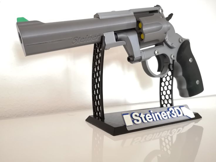
Prospects for printing weapons
The potential for 3D printing of firearms is far from exhausted. The expansion of equipment capabilities and the development of innovative materials indicate that in the near future such weapons may approach military weapons in terms of characteristics. In the future - a significant increase in the resource and the provision of automatic firing.
Significantly increases the reliability of printed pistols and carbines SLS technology using metal powder. Such weapons already differ little from the factory metal models. While it is very expensive, which significantly limits the application. However, over time, the material will become cheaper, which means it will become more affordable.
Printing firearms on a 3D printer has become a reality. Despite its extremely low performance and reliability, interest is growing in it. Experts predict that the printing of weapons will become widespread, and it is impossible to stop such production.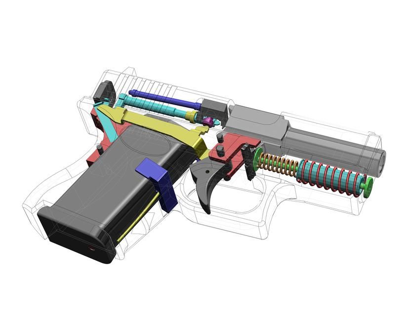 There comes a time when measures should be taken at the legislative level to establish effective control over this process.
- March 21, 2021
- 6864
Get expert advice
3D printer gun | Weapons printed on a 3D printer
With the help of 3D printing, you can make not only harmless souvenirs and trinkets. People did not limit themselves to the necessary mechanisms and things. Legislators were seriously worried, because enterprising designers and inquisitive minds tried to print weapons. And not just a model for cosplay, but a real one, capable of firing live ammunition. But most importantly, they succeeded! Therefore, it was necessary to introduce restrictions at the legislative level for the safety of people.
Weapons were printed not only by professional devices capable of metal printing.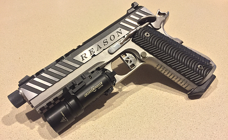 And quite ordinary ones, printing using FDM technology. At the same time, it was possible to print not only prototypes of existing weapon models, but also to develop completely unique models.
3D printed weapons - analogues
The most well-known variants of weapons analogues printed in whole or in part are:
- Сolt M1911 from Solid Сoncepts
- Replica of the grizzly .22 hunting rifle, made of plastic by a Canadian with the pseudonym "Matthew"
- Horns for AK 47 and AR-15 - Feinstein from Defense Distributed
- Parts for AK-47
Concept3d printable Solt M1911 printer. For this, an alloy of chromium, nickel and molybdenum called Inconel 625 was used. 2000 shots can be fired from this weapon. In this case, the number of misfires will be minimal.
A grizzly .22 plastic hunting rifle capable of firing 14 rounds, after which its barrel becomes unusable. The weapon was built through trial and error on a Stratasys Dimension 1200e.
Other legally restricted options are hybrid systems of existing firearms.
New Designs
Many have gone further and have not tried to print existing models of weapons, but have tried to create new unique models. The most famous among them are:
- Liberator and Lulz Liberator
- Shutu-MP1
- Reprringer Pepperbox
The very first additive pistol was the Liberator. This iconic weapon appeared in 2013. It is completely printed on a Stratasys Dimension SST 3D printer, and its cost is about $10. The drawings of this device were freely available. The disadvantages of this weapon were that it gave a lot of misfires, and was only capable of one shot. The shortcomings have been eliminated in the improved Lulz Liberator model. This plastic pistol is capable of firing up to 8 shots. Now the drawings are removed from the public domain.