3D printed aerospike engine
AMCM ups the Game in 3D Printed Rockets with World’s Biggest Aerospike Engine - 3DPrint.com
The leader in powder bed fusion printers, EOS and its sister company AMCM are stepping up their efforts to advance 3D printed space propulsion. Just last week, the company announced a partnership with Munich and Singapore-based software startup Hyperganic to accelerate innovation in space propulsion engineering. By integrating Hyperganic’s AI-powered algorithmic engineering software platform with EOS’ digital, high-end additive manufacturing solutions, the trio plans to revolutionize the field of space propulsion, which still uses very conservative designs.
As the first product in this collaboration, AMCM completed printing the world’s largest aerospike rocket engine on May 11, 2022, which was engineered using Hyperganic’s upcoming algorithmic engineering platform called Core. Set for release to a limited number of applicants on June 15, 2022, Hyperganic Core empowers designers to build 3D printing applications using advanced software algorithms without even a single piece of manual CAD.
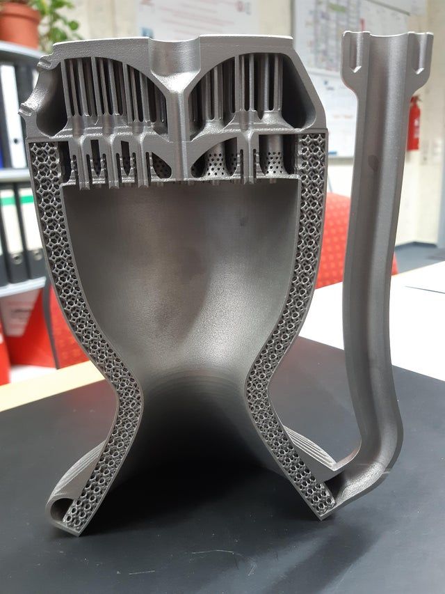
The result is what Hyperganic CEO and Co-Founder Lin Kayser described as “the most complex AM part ever produced.” In fact, according to the long-time entrepreneur, the novel part broke all conventional workflows. The aerospike engine was automatically reengineered for production on an AMCM M 4K large scale, high productivity system for demanding AM applications, using EOS CopperAlloy CuCrZr. Standing at 80 cm tall, the engine demonstrates what’s possible when the power of software algorithms is combined with advanced AM systems.
Algorithmically engineered aerospike rocket engine printed in copper at AMCM. Image courtesy of AMCM/EOS/Hyperganic.Both the private and public space sectors have turned to 3D printing technologies to advance rocket engine manufacturing throughout the last decade. From NASA to industry giants like Aerojet Rocketdyne and new startups like Launcher, many are traveling the AM road to develop and industrialize advanced 3D printed propulsion systems. So, why is this new engine so important to the space industry?
This technical innovation is supposed to make rocket engines more efficient than standard propulsion systems.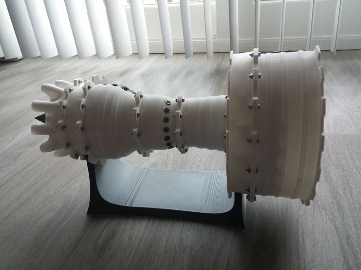 For decades, the aerospike engine has been considered a promising solution. Even NASA tested the concept extensively on the ground and hoped to incorporate it into the Space Shuttle program, but due to budget constraints, the orbiter ended up being equipped with tried-and-tested bell-shaped nozzles instead. However, now that this technology can be built and engineered thanks to new advanced manufacturing techniques and AM’s design freedom, we are starting to hear more about aerospike rocket engines.
Unlike the standard bell-nozzle rocket engine, the aerospike engine nozzle looks like a spike and has significant advantages over traditional designs. Kayser points out that it is “altitude compensating” and “does away with the heavy nozzle extension, with a spike in the middle instead.” Additionally, it is easily up to 20% more efficient than bell nozzle engines, which is a dramatic improvement in the field of rocketry where even fractions of percentage points are worth pursuing, says Kayser.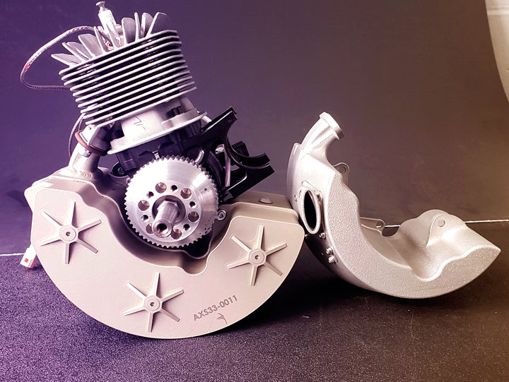
“The challenge was always cooling the spike in the middle of the extremely hot exhaust gas. With Additive Manufacturing, we can finally produce these kinds of objects, and a few startups have been successful in initial designs. The problem now is to create a reliably working engine that can power a spaceship. This requires many iterations — and iterations in CAD are prohibitively complicated, especially for complex designs. This is where Hyperganic Core and Algorithmic Engineering come into play,” explained the CEO.
Kayser refers to initial designs of 3D printed aerospike engines done by Spanish startup Pangea Aerospace, done in collaboration with the German Aerospace Center (DLR) and industrial AM expert firm Aenium. Developed in 2021, Pangea aimed to test several aerospike engine designs that engineers believe can improve rocket engine efficiency by up to 15%. DLR carried out the first hot-run tests of this innovative engine, demonstrating the success of the new technology.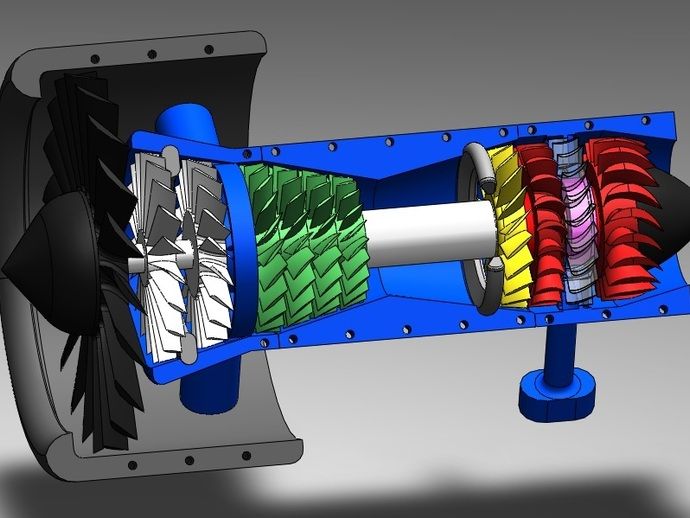 Now EOS, AMCM, and Hyperganic hope to take aerospike engines one step forward.
For the task, Hyperganic Strategic Engineering Lead Josefine Lissner created a completely algorithmic model for various aerospike designs. Within minutes, the team claims they can create almost any engine design imaginable, including injector heads, advanced heat transfer systems, and complex combustion chamber geometries with different thrust levels and sizes.
Selected from the many hundreds of designs, the first aerospike engine design was produced by Hyperganic in mere days. Then it was printed in one job on an EOS M 400-4 with zero supports, thanks to the newly launched EOS NickelAlloy IN718 process. After EOS had its first Inconel aerospike engine, it was automatically reengineered for production on the substantially larger AMCM M 4K system in copper. Dubbed by the companies as “the world’s largest 3D printed aerospike rocket engine,” this final copper engine was built from the ground up using Lissner’s Hyperganic Core algorithms.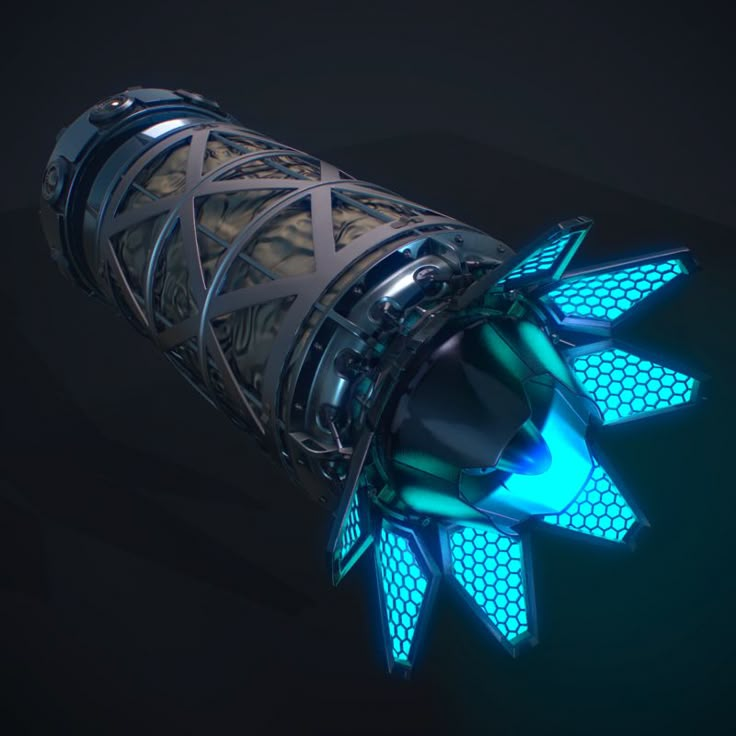
The actual parts can be seen live at the upcoming RAPID + TCT event on May 17 through 19 in Detroit and at the Space Tech Expo USA in Long Beach, California, October 6 through 8.
Stay up-to-date on all the latest news from the 3D printing industry and receive information and offers from third party vendors.
Tagged with: 3D printed engine nozzles • 3D printed propulsion • 3d printed rocket engine • aerospike rocket engine • AMCM • AMCM M4K • copper aerospike engine • eos • EOS M 400 • Hyperganic • Hyperganic core
Please enable JavaScript to view the comments powered by Disqus.
World’s Largest Printed Aerospike Engine Unveiled
Traditional rockets are incredibly inefficient for a number of reasons, not least due to the fact that they are mostly disposable.
But reusability aside, another reason that rockets are inefficient is the fixed geometry of the bell nozzle.
Efficient rocket thrust is dependent on the exhaust gas going in the correct direction (opposite to direction of travel, ideally).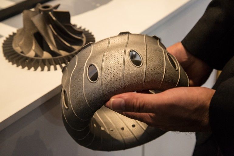
A bell shaped rocket nozzle (also called a convergent/divergent, or “con-di” nozzle) shapes the exhaust gasses so they flow out in more or less a straight vector. But as it exits the nozzle, the flow encounters the atmosphere, which also shapes the flow.
Aerospike engine (Image credit: Hyperganic)At low altitudes, the ambient pressure is enough to tame the flow into a straight path. However, once the altitude increases and the ambient pressure decreases, the pressure affects the flow less and hence the exhaust “expands” as it exits the nozzle. This results in a loss of thrust as the altitude changes, because a con-di nozzle is optimized for lower altitudes.
Of course, it would be lovely to have some kind of morphing nozzle that varies its geometry as the altitude changes, but such a device would carry a huge mass penalty, which is not good for rockets. Some rockets use a nozzle extension to offer some compensation, however this also carries a huge mass penalty.
Another solution is to use an aerospike engine, as seen in the picture above.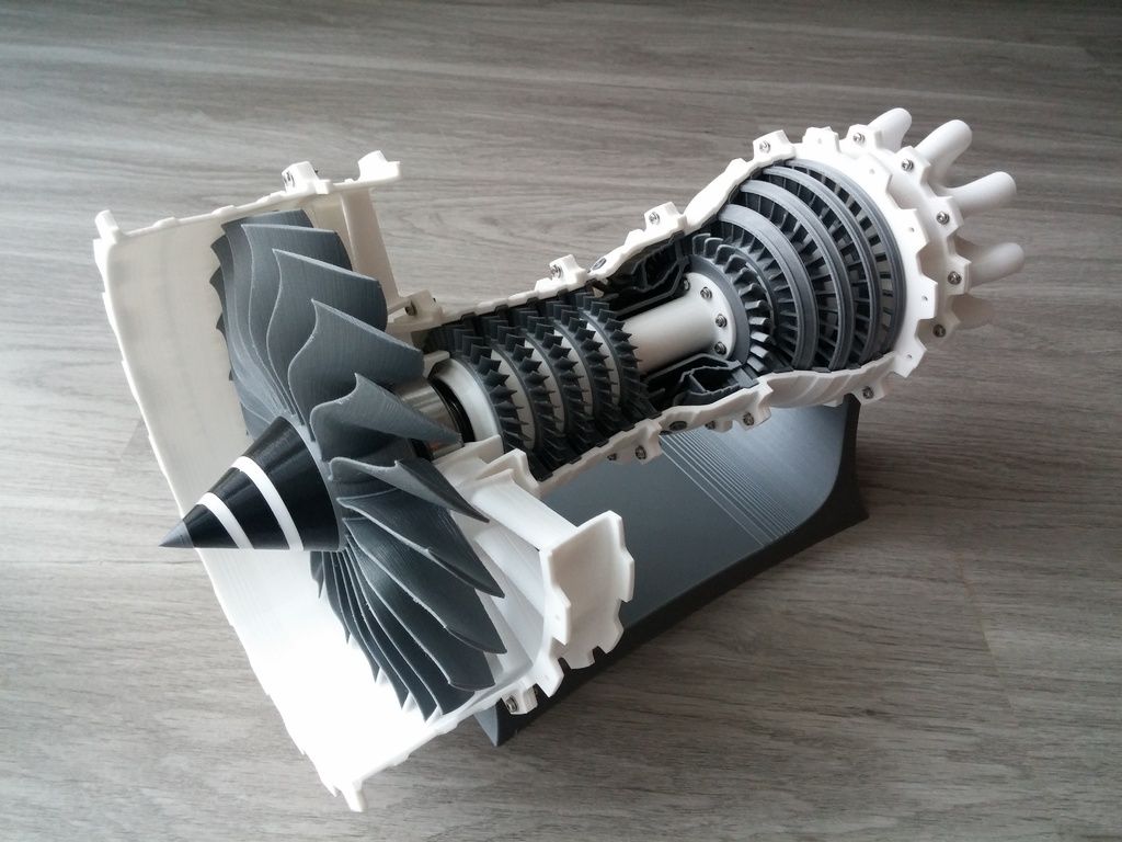 The aerospike engine, due to its operating principles, performs optimally across a range of altitudes and can increase efficiency significantly.
On an aerospike engine, rather than having the exhaust flow pushed against the nozzle wall where it will expand outwards as it leaves the nozzle at higher altitudes, the flow is pushed inward against the nozzle spike, and so expansion problems are eliminated.
These engines have existed in conceptual form or as test items for decades, but the problem has been with the cooling requirements for the middle spike. Additive manufacturing is now enabling the cooling channels to be manufactured with relative ease.
Hyperganic has not only made the world’s largest printed aerospike (measuring 80cm tall) but they have done so without any manual CAD inputs at all.
Apparently their algorithmic design software will churn out aerospike designs all day long based on a few inputs, and will generate complex designs that cover all aspects of the engine including spike geometry, cooling channel paths and injector parameters.
This is pretty handy, because as anyone who has attempted to design a rocket engine can confirm, most of these parameters are dynamically linked in some way, so changing one thing totally screws with everything else. Hence a parametric approach is preferred, and an AI assisted or algorithmic approach is even better for iteration.
The Hyperganic aerospike is printed in what appears to be copper, or maybe even mixed metals, as we have seen before.
So the big question remains…
Does it actually work?
Printing fancy looking motors is one thing, but the proof as always is in the pudding.
The pudding in this case will be full motor tests, and we await these results eagerly!
Is it safe to print aircraft engines on a 3D printer? Monash assembled the engine, entirely printed on a 3D printer:
This is not an isolated case. Boeing and Airbus have long been involved in additive technologies - when a 3D printer manufactures a part in layers, focusing on a computer model.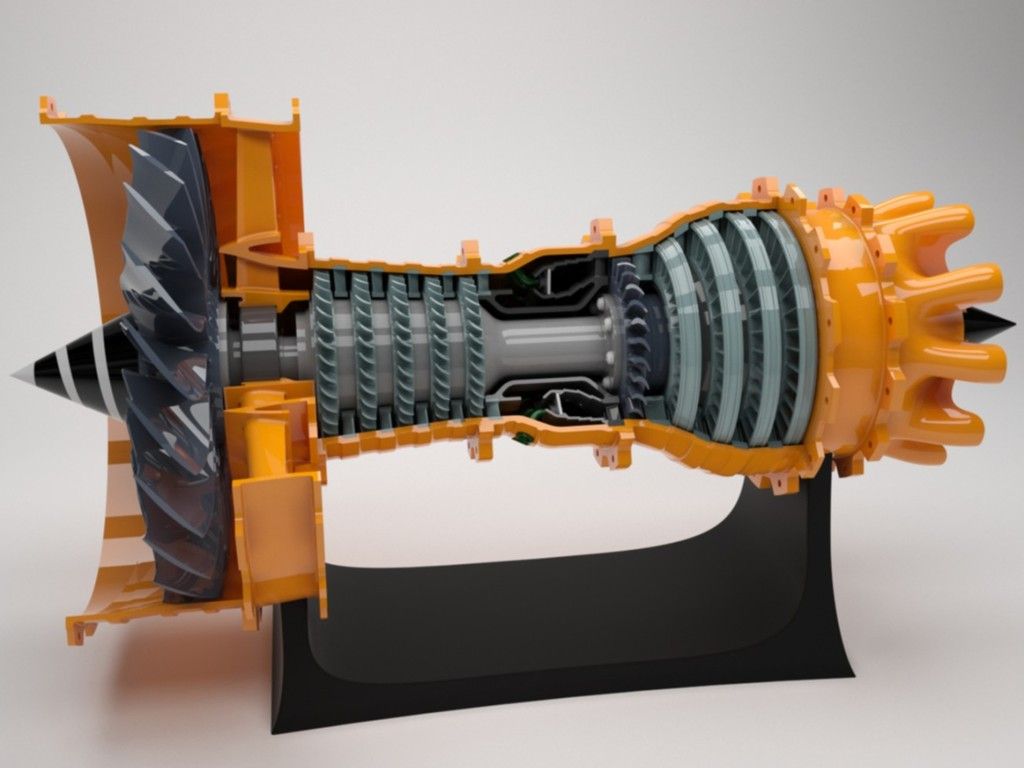 For example, each Boeing 787 passenger airliner has about 30 parts printed using this algorithm, and the Airbus A350 and A320neo have a whole titanium bracket that connects the wings to the engine.
In 2016, Airbus unveiled the world's first fully 3D printed Thor aircraft. It, of course, looks more like an aircraft model: length - 4 m, weight - 21 kg, remote control.
Russia is not far behind. In 2020, a plane with a 3D printed engine was tested in Kazan. A light drone flew at an altitude of 170 m and moved at a speed of 150 km/h. Larger parts are also being printed in Russia, for example, for the new MS-21 airliner and the K-226 helicopter. They are created at the 3D printer farm of the Rostec Additive Technology Center.
How parts are printed
At Rostec, parts are printed from metal — but in the form of a powder with certain properties and granule sizes. At the same time, each 3D printer is designed for a certain type of metal and cannot print on another material.
First, a device inside the printer deposits a layer of metal powder on a special platform. Then a laser, running according to a predetermined program, heats and fuses this layer of powder, causing it to harden. Then the platform on which the cultivation takes place is lowered by the thickness of the layer, and everything repeats. This happens several times, layer by layer. Depending on the size of the part, the process lasts from several hours to several days.
The benefits of 3D printing
- Parts become lighter. This is important in the aircraft industry: the weight saved can be used, for example, for additional passenger or luggage space.
- Environmentally friendly. When creating parts in the traditional way, the desired element is cut out of a piece of metal, and the rest is thrown away. While working on a 3D printer, there is practically no waste.
- Create forms that cannot be reproduced in other ways.
- Fast part creation speed.
It is worth noting that it is unlikely that a 3D printer will ever print parts that are cheaply and quickly manufactured using standard technologies.
Printer giant and printer repairman
Not all 3D printers are designed for the same tasks. For example, the Rostec Additive Technology Center has a large 3D printer capable of printing parts up to half a meter in size. Boeing uses printed titanium engine components on its Dreamliner 787 passenger jet.
At the same time, an airplane is not the only thing that can be created on a 3D printer. Relativity Space, for example, wants to launch the world's first fully 3D-printed rocket into orbit in 2021. And these are not some dreamers dreaming about the stars: they have already attracted $700 million in investments, which means they believe in the project.
Another item of interest is Printer Repair . He is able not only to print parts according to a given program, but also to repair them.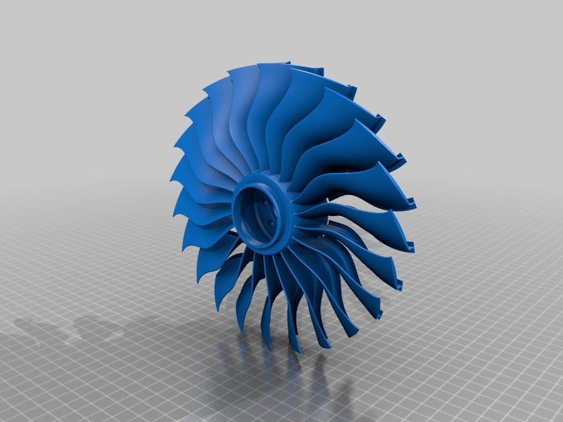 This machine works a little differently: using direct metal printing technology.
This mechanism consists of two main elements. The first is a source of laser radiation, the second is a special nozzle through which powder is fed in a jet of inert gas. The gas jet and the laser beam are focused at one point, where the powder melts and the part grows. The printer allows you to repair broken parts instead of throwing them away. In this case, the part does not lose its original properties.
To repair a part, it must be scanned. Another option is to specify a control program where there is a 3D model of this part with a broken section. However, a 3D scanner is most often used, which allows you to get an exact sample of a part that is already there. Based on this model, a control program for repair is developed.
Why you need a 3D scanner
It is the 3D scanner that checks the quality of all aircraft parts that are created on a 3D printer. All of them must be perfect.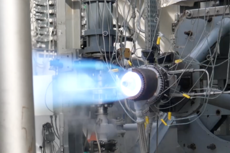
In addition, the technology makes it possible to make structures that cannot be created by standard methods - for example, a bracket. It would consist of several parts and, accordingly, several machining and assembly operations would have to be done. All this takes time, and the 3D scanner makes it possible to speed up the process.
A 3D-printed prototype of a landing pad for the Moon was tested / Sudo Null IT News
It is almost impossible to imagine space exploration without the use of local resources. Lunar base projects were buried under the surface, sprinkled with soil or surrounded by printed walls. But less attention was paid to the buildings of the lunar cosmodrome - at best, flat areas are drawn in the illustrations. They will have a minus - the engine exhaust will corrode the surface and raise dust. To address these potential challenges, a team of students from ten U.S. universities and colleges, with support from NASA and 3D printing company ICON, designed, built, and successfully tested a large-scale prototype of the Lunar PAD airstrip.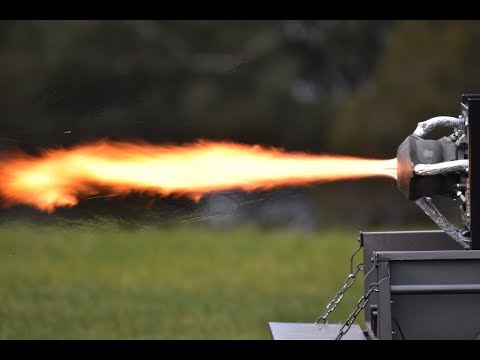
In the summer of 2019, a team of students from the NASA L'SPACE Virtual Academy won a round of the 12-week NASA NPWEE Technology Concept Proposal course and received funding to develop their concept for protecting lunar landers from dust using robotic construction. The goals of both L'SPACE and NPWEE are to expand the pool of high-quality proposals of new concepts and technologies that can then be useful to NASA. In 2020, the team submitted a revised concept to an online technology readiness review and received funds to build and test a scale model. After spending hundreds of working hours consulting with NASA experts, the students went from idea to implementation of a model of the potentially important task of creating a safe reusable landing site for the Moon. In autumn, a scale model was built at Camp Swift, Texas, and successfully tested by a geophysical rocket engine in early March.
A team of students at work, photo ICON The project, originally called the Dust Devil ("dust whirl"), is eventually called the Lunar Plume Alleviation Device ("Lunar device to soften the exhaust") or, for short, Lunar PAD (playing on what that in English "pad" also means "a platform for launch / landing"). Structurally, the Lunar PAD consists of two levels: the upper one is a flat platform with small slots for exhaust gases to drain.
The lower level combines load-bearing structures and flues for exhaust gases to the sides. A feature of the project is the use of 3D printing. First, a 3D construction printer forms a frame, which, as is often the case in additive manufacturing, uses complex surfaces and looks aesthetically pleasing.
Frame and student team, photo by ICONPrinting process, top view, photo by ICONThe printed frame is then filled with filler. The test mock-up used a cement-based material, but for lunar conditions, it would be logical to produce a hardening or sintering regolith building material in situ. The structure built is strong enough to withstand the takeoff and landing of the lunar modules, and produces less dust by diverting engine exhaust into the gas ducts.
Even at the construction stage, sensors were installed in the model to determine temperatures, loads and gas flow.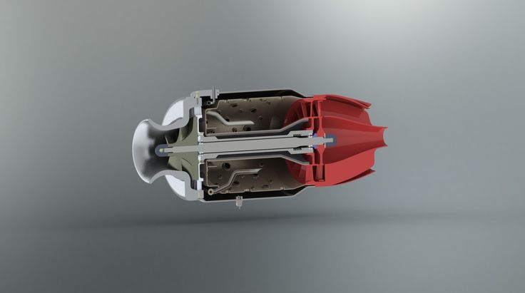 In early March, a geophysical rocket team from Texas A&M University delivered a solid rocket motor to a test site. It was installed above the site, launched and looked at the information recorded by the sensors. The tests were successful - the Lunar PAD pad successfully withstood the takeoff / landing simulation, the data obtained do not contradict the calculated ones.
The project has already received its first scientific publication in the AIAA SciTech Forum materials, and a very diverse group of college and university students scattered throughout the United States can take part in a full-fledged and successful scientific and technical project, potentially in demand in future projects moon bases.
It is also interesting to note that ICON, which provided the gantry 3D printer for the project, is also 3D printing houses and other structures. The company also received a contract from NASA last fall to research and develop a construction system that could be used on the moon.