3D print prevent stringing
Stringing or Oozing | Simplify3D Software
Stringing or Oozing
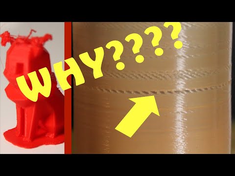
Stringing (otherwise known as oozing, whiskers, or “hairy” prints) occurs when small strings of plastic are left behind on a 3D printed model. This is typically due to plastic oozing out of the nozzle while the extruder is moving to a new location. Thankfully, there are several settings within Simplify3D that can help with this issue. The most common setting that is used to combat excessive stringing is something that is known as retraction. If retraction is enabled, when the extruder is done printing one section of your model, the filament will be pulled backwards into the nozzle to act as a countermeasure against oozing. When it is time to begin printing again, the filament will be pushed back into the nozzle so that plastic once again begins extruding from the tip. To ensure retraction is enabled, click “Edit Process Settings” and click on the Extruder tab. Ensure that the retraction option is enabled for each of your extruders. In the sections below, we will discuss the important retraction settings as well as several other settings that can be used to combat stringing, such as the extruder temperature settings.
Common Solutions
Retraction distance
The most important retraction setting is the retraction distance. This determines how much plastic is pulled out of the nozzle. In general, the more plastic that is retracted from the nozzle, the less likely the nozzle is to ooze while moving. Most direct-drive extruders only require a retraction distance of 0.5-2.0mm, while some Bowden extruders may require a retraction distance as high as 15mm due to the longer distance between the extruder drive gear and the heated nozzle. If you encounter stringing with your prints, try increasing the retraction distance by 1mm and test again to see if the performance improves.
Retraction speed
The next retraction setting that you should check is the retraction speed. This determines how fast the filament is retracted from the nozzle. If you retract too slowly, the plastic will slowly ooze down through the nozzle and may start leaking before the extruder is done moving to its new destination. If you retract too quickly, the filament may separate from the hot plastic inside the nozzle, or the quick movement of the drive gear may even grind away pieces of your filament. There is usually a sweet spot somewhere between 1200-6000 mm/min (20-100 mm/s) where retraction performs best. Thankfully, Simplify3D has already provided many pre-configured profiles that can give you a starting point for what retraction speed works best, but the ideal value can vary depending on the material that you are using, so you may want to experiment to see if different speeds decrease the amount of stringing that you see.
Temperature is too high
Once you have checked your retraction settings, the next most common cause for excessive stringing is the extruder temperature. If the temperature is too high, the plastic inside the nozzle will become less viscous and will leak out of the nozzle much more easily. However, if the temperature is too low, the plastic will still be somewhat solid and will have difficulty extruding from the nozzle. If you feel you have the correct retraction settings, but you are still encountering these issues, try decreasing your extruder temperature by 5-10 degrees. This can have a significant impact on the final print quality. You can adjust these settings by clicking “Edit Process Settings” and selecting the Temperature tab. Select your extruder from the list on the left, and then double-click on the temperature setpoint you wish to edit.
Long movements over open spaces
As we discussed above, stringing occurs when the extruder is moving between two different locations, and during that move, plastic starts to ooze out of the nozzle. The length of this movement can have a large impact on how much oozing takes place. Short moves may be quick enough that the plastic does not have time to ooze out of the nozzle. However, long movements are much more likely to create strings. Thankfully, Simplify3D includes an extremely useful feature that can help minimize the length of these movements. The software is smart enough that it can automatically adjust the travel path to make sure that nozzle has a very short distance to travel over an open space. In fact, in many cases, the software may be able to find a travel path that avoids crossing an open space all together! This means that there is no possibility to create a string, because the nozzle will always be on top of the solid plastic and will never travel outside the part. To use this feature, click on the Advanced tab and enable the “Avoid crossing outline for travel movement” option.
Movement Speed
Finally, you may also find that increasing the movement speed of your machine can also reduce the amount of time that the extruder can ooze when moving between parts. You can verify what movement speeds your machine is using by clicking on the Speeds tab of your process settings. The X/Y Axis Movement Speed represents the side-to-side travel speed, and is frequently directly related to the amount of time your extruder spends moving over open air. If your machine can handle moving at higher speeds, you may find that increasing this settings can also reduce stringing between parts.
Related Topics
How to Avoid 3D Print Stringing: The Ultimate Guide
Printing with FDM technology might result in a number of defects due to incorrect mode, uneven quality of consumables, or some printer-related issues. We will consider the process of thread formation during nozzle movement, generally known as stringing or oozing.
What causes filament stringing?
When the nozzle is idly moving from one printing area to another within one layer, the melted filament may slightly leak and form a string between the start and end points of the route. The defect occurs most often with PETG printing, but it is possible with other materials as well.
The main causes of stringing are:
- incorrect retraction settings;
- excessive nozzle temperature;
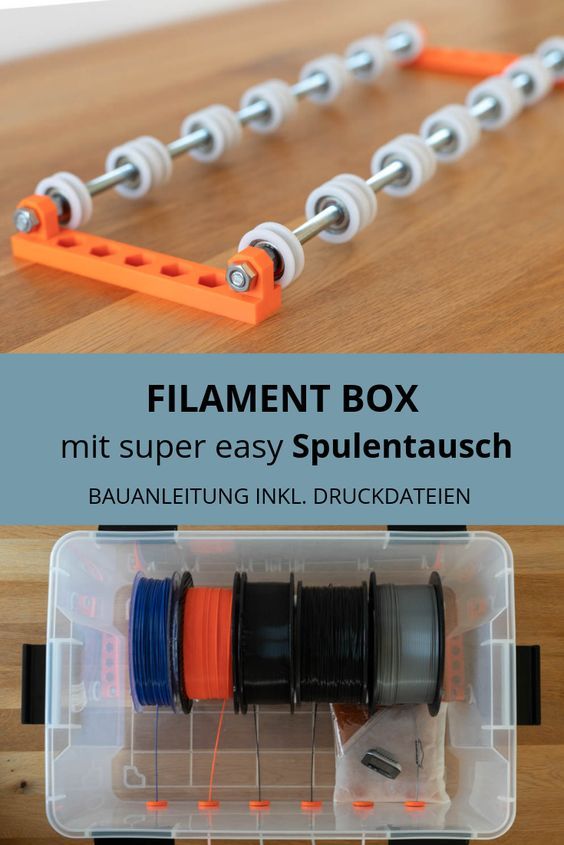
- filament exposed to humidity;
- low print speed;
- external nozzle contamination;
- defective nozzle;
- large melt zone or a large diameter nozzle.

It might be hard to determine a specific cause from external signs, that is why it is better to consistently check and rule out all the possible reasons.
Major problems and their solutions
Humidity
Wet filament makes it drastically more difficult to adjust the print mode, and it is relatively easy to detect excessive humidity.
Extremely wet PETG. Characteristic features can be clearly seen: loose surface of the part, filament lint over the entire length of the threads.
It is widely believed that PLA, PETG, and ABS have little moisture absorption. Indeed, many users do not encounter problems with wet filament. At the same time, manufacturers offer drying modes for most of their consumables.
When printing with damp filament, there is usually an extraneous sound similar to hissing or crackling. The surface of the printout comes out matte and porous, and strings are formed over the non-print area.
Credit: maker.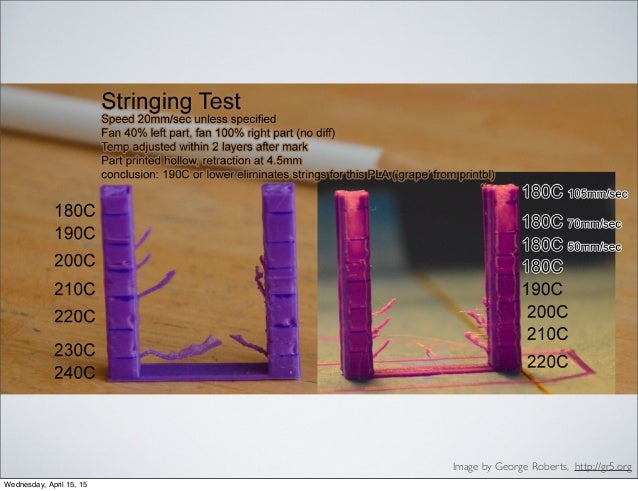 pro
pro
In this case, threads occur when water in the filament starts to boil, and the steam provides an excessive output of plastic. When these signs are recognized, drying is definitely necessary.
Incorrect feeding and temperature
Wet filament is a factor that can be detected separately, but the others are similar and should be dealt with sequentially. To begin with, it is necessary to make sure that the right amount of plastic is fed and the temperature regime is correct. Overextrusion manifests itself in oozing blobs, distorted geometry of the print, and ribbed horizontal surfaces.
Credit: prusa3d.com
And in this case, strings are formed when an excessive amount of plastic starts leaking from the nozzle during its idle movement.
There are special test patterns called "temperature towers" to check the temperature mode. These are a sequence of vertically positioned identical elements printed at different nozzle temperatures.
There is also a plugin for automated creation of test patterns in Cura, so let's see how it works. To install the plugin, you must create an Ultimaker account and log in to it. This will give access to the repository.
Install the Calibration Shapes plugin. After reloading the slicer, the Parts for calibration item appears in the Extensions menu.
To set up the PETG print temperature, select Add a PETG TempTower. The temperature tower model will appear on the screen. Now it is time for a post-processing script (a set of scripts will be installed with the plugin).
The settings in the screenshot above are set for a temperature tower with a range from 260 °C to 230 °C in increments of 5; the layer height is 0.2 mm.
For PETG, it might make sense to print a second tower with lower temperatures. For instance, it applies to PLA+. The settings are the same, only the starting temperature is 230 °C.
A tower allows visually selecting the correct print temperature. A temperature that is too high results in blobs, indistinct outlines, and a large number of strings. Lower temperatures lead to disruptions in feeding and poor mechanical strength of the part. Our towers in the photos show that evident stringing stops after 230 °C, and at 215 °C there are issues with feeding and layer adhesion. That is why 220 °C will be the optimum printing temperature for this particular filament on this particular machine. Therefore, set the appropriate value in the Printing Temperature field and make sure that the other temperatures are synchronized (they are dependent on the first value, but can be set manually).
Incorrect retraction
Retraction is used to prevent unwanted plastic leaking from the nozzle. This function will pull back the extruder before moving it over the non-print area. The basic settings for retraction in the slicer are length and speed. Insufficient length is a common cause of stringing. Excessive length leads to thread stretching, plastic getting into the cold zone, insufficient feed after moving the nozzle to the finish point, or plugging.
At too high a speed the thread will break in the melt zone or cause feed slippage. At too low — the thread will stretch without being pulled back inside the nozzle.
Terminal example: high print temperature with disabled retraction.
Typical values at which it is reasonable to start adjusting retraction are 30 mm/s speed, 1–2 mm length for a direct extruder, and 5–7 mm length for a Bowden. For instance, in Cura, retraction can be adjusted in the Travel section.
To check retraction, test patterns like "four square cones" are printed, but there are more functional tests to select retraction mode by analyzing a single printout. For example, this service generates a G-code with different retraction settings. It should be used with caution, because a large number of retracts per unit time occur during printing.
This service allows determining the optimal settings without having to reprint the test several times.
The default settings need to be adjusted for the printer in use.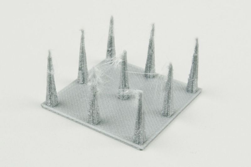 You can also reduce the number of vertical iterations — too high retraction makes no practical sense.
Appropriate settings for Kingroon KP3S with 0.4 mm nozzle, PETG.
The settings to attend to:
- X Dimension and Y Dimension.
- Nozzle Diameter.
- Filament Diameter.
- Start Temp — the optimal temperature for printing with the given material we have set in the previous step, or use the temperature recommended by the manufacturer.
- Extrusion Multiplier — the rate obtained by adjusting. At 1.0 there was a case of overextrusion, so here it is reduced to 0.97.
- Bed Temp.
- Number of Tests — we recommend to reduce it to 10, too high retraction speeds makes no practical sense.
- Travel Speed — idle speed, depends on the capabilities of the printer. Usually 80–150 mm/s.
- Custom Gcode — leave it as it is; if you need auto bed leveling before printing, delete ";".
- All other settings can be left by default.
The point of the test is as follows: the retraction length increases in increments of 0.5 mm along the perimeter, i.e. from 0.5 to 8 mm. The retraction speed increases with height, from 10 mm/s in increments of 5 mm/s.
The printout shows that when you increase the retraction length more than 1.5 mm, the quality of the protrusion does not change.
The photo shows the inadequate feed after retraction, which occurs when the length is too long and the speed is too high.
The final retraction length not only depends on the plastic and the type of extruder, it is also affected by a number of other parameters, such as the cooling efficiency of the hotend and design of the thermal barrier. Therefore, the settings for the same spool installed on different printers can vary significantly.
The printed test does not allow determining the exact retraction speed, so choose a standard value of 30 mm/s to avoid filament break and print at normal speed.
The "four cones" test, printed with the settings selected earlier. The retraction length is 1.5 mm, the speed is 30 mm/s. The printer is a Kingroon KP3S with the Titan direct extruder. Note that the printing of relatively large objects produces fewer strings than with "cones".
By comparison, the same test with PLA. No stringing already at a retraction length of 1 mm.
Different slicers have additional features designed to improve retraction performance and reduce stringing. For example, in Cura, it is Combing — moving to the next section not in a straight line, but over the already printed path.
Cura 4.11.0
If the Combing mode is on, stringing may be reduced. However, its use often leads to certain surface defects where it contacts with the nozzle.
Other factors
Worn or low-quality nozzles can also contribute to stringing. A normal nozzle has a thin channel in front of the outlet, but there are also nozzles that have virtually no channel. Practice shows that in the second case, the retraction works worse. Finally, it is reasonable to check that the nozzle is clean. The filament leftovers will drip and stick to the printout.
The inside of a quality nozzle.
Here, there is practically no output channel.
Speed also matters. It is more likely that the plastic will leak more at a low speed. The upper end is determined by the capabilities of the printer. On average, this value is in the 80–150 mm/s range.
Bottom line
To minimize stringing, you should first make sure that the filament is dry and that the temperature and feeding rate are correct. Only after that is it reasonable to proceed to the retraction settings adjustment. Specific length and speed will depend not only on the plastic, but also on the design of the extruder and the printer's hotend.
short tips for the transition from a CAD model to a printed object / Sudo Null IT News
was withdrawn from publication due to a technical error.Please be understanding. Thank you!
Whether it's just a hobby or a source of income, 3D printing is always based on product design. Those accustomed to traditional technologies will have to rethink the entire approach to product design and manufacture.
When the project is ready, a number of additional operations are performed: setting the orientation of the model and other parameters that ensure the proper printing process. In addition, it is necessary to take into account the fact that most 3D printers allow you to choose the degree of filling the model with cellular structures. The correct choice of this parameter provides protection of the object from deformation and destruction during the printing process, as well as significant savings in material and reduction in production time.
Finally, the last factor influencing the success or failure of the 3D printing process is the strength of the connection between the model and the table. If the workpiece is separated from the table during printing, then all the work will go down the drain.
Here, we'll walk you through the 3D printing process and give you some simple tips on how to use additive manufacturing in the design phase. In addition, we will dwell on the methods of preparing a finished project for printing, and also consider ways to securely fasten the workpiece to the table.
These guidelines apply primarily to Fused Deposition Printers (FDM) printers, but may apply to other types of printers as well. The process of obtaining a finished part by 3D printing is basically the same regardless of the method used.
Designing an object
Any 3D printing starts with construction. If you are developing a product yourself, then you need to build a 3D model of it in a computer-aided design (CAD) system to turn the designer's idea into reality. In this case, the object can be both very simple and very complex. However, too thin and too small models should be avoided.
3D-CAD from Siemens from this article for 49900r (90% discount), the promotion is valid until March 20, 2020. Read more>>
Saving the file in a special format for printing
To print an object, its model must be saved in a special file format - for example, STL, which has become the de facto standard in the world of 3D printing. In this format, model surfaces are represented as a grid of triangles. Simple surfaces are broken down into a small number of triangles. The more complex the surface, the more triangles you will need. Today, other formats are used in 3D printing, in particular, the 3MF format developed by Microsoft. But the most common is still STL.
CAD systems make it very easy to save the model in the desired format: just click the Save As command. To improve print quality, it is desirable to set a number of settings for saving to the STL format - for example, the tolerance during transformation and the angle of the plane. The lower the conversion factor and the better the angle, the smoother the printed part will be.
Opening the file in the slicer program
Most, if not all, 3D printers come with their own slicer software. The slicer loads the STL file created in the CAD system and cuts it into layers, and then creates a control program for the printer.
Place the model correctly in the print space
After entering the print settings, the model (or several models) needs to be placed on the printer table. You can print many objects on one table at once. At the same time, compared to printing a single object, the time slightly increases, but in general it still turns out to be less. Here are some tips for choosing the right model orientation.
Set parameters
In the slicer program, the user sets parameters such as print speed, material consumption, nozzle and desktop temperatures. Most slicers have simple settings for beginners. In this case, most often there are also advanced settings so that experienced professionals can achieve optimal results. Advanced settings include percentage infill, amount of backing material, and type of backing or raft (this is a small, thin base that keeps the printed part stable. The backing is removed when it's finished). The number of options is truly endless. Specific settings vary depending on the brand of printer. It's easy enough to set them up.
Sending the control program to the printer
After setting the print settings, the placement of future objects on the table, their orientation and quality, it's time to finally start the printer. It is enough to press the Print button and find something to do while the production is in progress. Depending on the complexity of the design, the process takes from several minutes to several hours.
Finishing
Finishing includes removing the printed part from the table, as well as removing the support material by melting, mechanical separation or dissolution (depending on the design of the printer).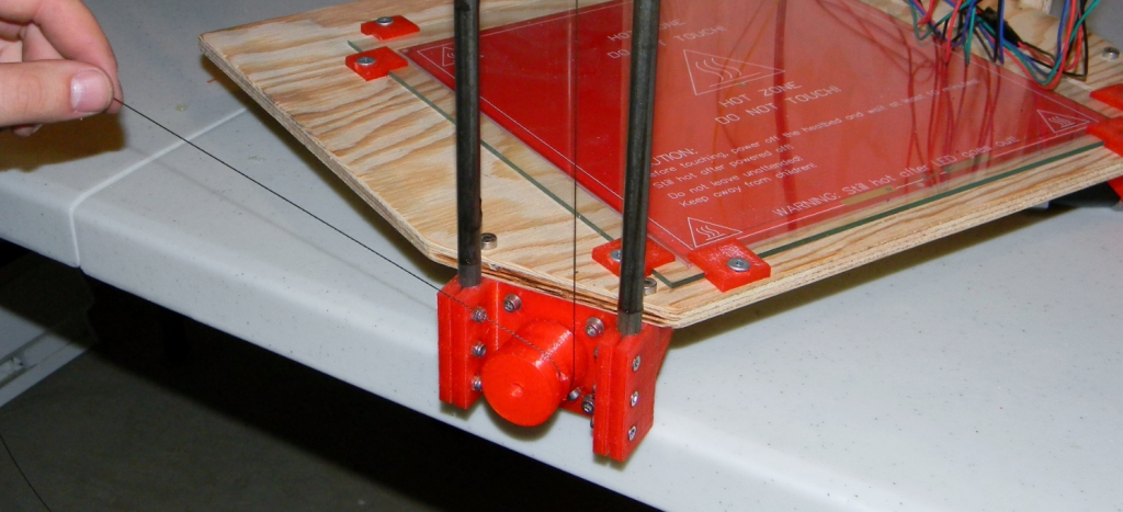 The part may require some light sanding or polishing, but overall a properly printed object looks good from the start. Other types of finishing are placing plastic parts in a container with acetone to smooth out surface roughness, gluing (if the dimensions of the structure exceed the dimensions of the 3D printer or individual elements of the object must have different orientations), drilling holes and painting.
3D printing process
3D printer design considerations
Eliminate sharp corners
If the direction of the surfaces changes abruptly (for example, a vertical wall intersects with a horizontal overlap), then such a model is difficult to print. The printer will build excessive inner surfaces, wasting too much material. There are two easy ways to prevent this: add chamfers to smooth out where the surfaces meet, or round the corners so the printer gradually builds a vertical surface.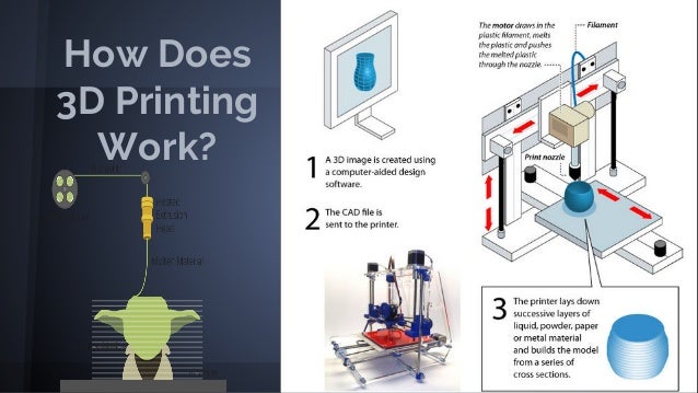 In addition, rounding will increase strength, since destruction most often occurs at sharp corners.
Elimination of thin walls and small geometries
Layer by layer fusing technology consists in supplying hot plastic through a nozzle with the formation of a printed object layer by layer. The thickness of the extruded plastic layer cannot be made smaller than a certain limit, depending on the diameter of the nozzle and the speed of the print head. Excessively thin-walled details are difficult to print - often the result is a chaotic weave of fibers. If the part can be printed, it is very fragile and breaks easily.
Too thick walls - also bad
On the other hand, if the walls are too thick, they become brittle and crack easily. This is especially important when printing from materials other than resins, as excess thickness during the manufacturing process leads to internal stresses in the part. Even when printing from plastics, material is wasted on walls that are too thick and time is wasted.
Removing large overhangs
3D printers allow you to create amazing shapes and surfaces, but they are not capable of printing directly in the air. If there is a void in the part with material above it, additional support material must be used. Most slicers add material automatically, but require you to specify the orientation and volume of the support structure. Printers with a single nozzle create an array of thin columns, which then have to be broken off. The result is an uneven surface. Therefore, it is recommended to avoid large overhanging elements whenever possible in order to reduce the need for support material.
If such an element is unavoidable, you can try to flip the object. Most printers are capable of printing overhanging elements with an angle of about 45 degrees. At a certain height, the edge of such an element may sag somewhat. The actual capabilities of a particular printer are determined by trial and error.
Holes shrink
Remember that the part is made of heated plastic. As it cools, it inevitably shrinks. Therefore, holes and other critical structural elements have to be made larger so that after shrinkage their size is as close as possible to the required one.
However, if you need to make a tight tolerance hole, it is better to print it with a smaller diameter and then ream it with a suitable tool. This is especially true for holes whose axis is parallel to the printer table.
Increasing the footprint
If the area of contact between the object and the base is small, the part may separate from the table during printing. To prevent this from happening, wide bases are added to the model legs, which are installed on the printer table. In general, the closer to the table, the more material must be added to the support.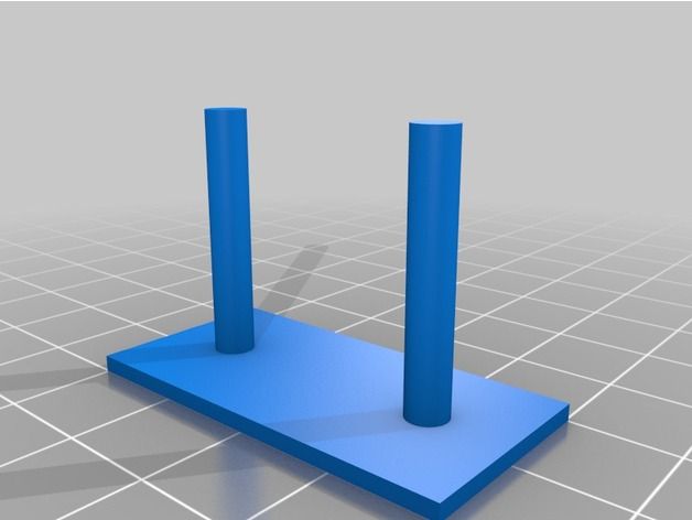 There are other ways to securely fasten the part to the table, which we will discuss a little later.
Special moves
The right approach to design makes printing easier. In addition, there are special post-processing techniques that are important to be aware of.
Place round surfaces vertically
The model should be oriented so that the minimum amount of support material is used. Ideally, it should rest on the table with a large flat edge. In addition, circular geometry must be placed so that the circular faces are vertical. If we look at the printer table from above, we should see a round silhouette of the object. In this case, the part comes out as symmetrical as possible with the formation of a solid round structure.
Place voids and holes vertically
If there are voids in the model (for example, it is a rectangular pipe), it is desirable to place such voids vertically in order to reduce the volume of the support material. If you print the pipe in a horizontal position, you will have to provide support for the entire inside. If you put the pipe on the end, then no support is required at all.
The same is true for holes: to get a hole with a straight axis, it is best to print it vertically - in the form of a stack of rings, which avoids warping or deforming a round hole into an oval one.
Set print quality settings
Proper selection of print parameters, such as STL conversion tolerance and slicer software settings, allows parts to be produced with a surface quality that matches that of cutting. However, this entails an increase in print time. When choosing quality parameters, one should proceed from the purpose of the object: is it a finished product or a prototype? Will the part be visible or hidden?
The quality parameters also affect the shape of the holes in the part. In CAD files, holes are represented as a set of straight lines at an angle to each other. The higher the quality of the model in the saved STL file, the less the circle looks like a polygon.
Reducing the layer thickness
To obtain the best quality, especially when using layer-by-layer deposition technology, it is necessary to reduce the thickness of the layers. It does increase the print time, but the end result is worth it!
Optimizing the filling with honeycomb structures
In terms of strength, objects do not have to be solid. Similar to a honeycomb, printers can create a honeycomb infill that balances strength and saves expensive polymer material. However, if the printed part serves as a prototype for strength testing, and the serial product will be manufactured by traditional methods, and also if the part is subjected to certain types of mechanical stresses and pressures, a solid design will be preferable.
Choosing a material
The success of printing largely depends on the correct choice of material. Materials have different properties. For example, the melting point of thermoplastic polyurethane (TPU) and polylactic acid (PLA) is lower than that of acrylonitrile butadiene styrene (ABS). In addition, the material is taken into account when choosing the type of support structures. For an object made of polylactic acid, supporting elements can be made from the same polylactic acid, since it will be quite easy to separate them from the finished part. If the part is printed from ABS plastic, then the support elements must be made from a different material, and it is better not to use such elements at all in thermoplastic polyurethane parts.
Cellular filling
A solid body is not always the best choice for 3D printing. Printing solid parts has its advantages, but the internal honeycomb structure saves both expensive material and time.
Creating objects with a specified degree of filling with honeycomb structures is a unique opportunity for 3D printing. Moreover, it is not required to design such a structure: this is done by the slicer program. As a rule, it is enough to set only the percentage of filling (the closer it is to 100, the more solid the object will turn out) and select the type of cells, if the printer has such an opportunity.
In addition to saving time and material, the internal honeycomb structure has many other advantages.
Cellular filling prevents warpage
Printing large objects as a single piece introduces a danger of warpage. By reducing the infill percentage, the air during printing passes through the part, providing more uniform cooling and eliminating warping.
Cellular filling does not lead to loss of strength
Printing cells instead of solid material does not reduce the strength of the part. In many cases, a honeycomb part is strong enough for the chosen application, but lighter and less material intensive.
The function determines the choice of cell geometry
Most slicers support a wide variety of cell geometries. The optimal option is determined by the functional purpose of the object. Standard box padding simplifies printing, while hexagonal and triangular boxes add strength. Wave fill allows the object to bend or twist.
How to choose the right filling percentage?
In general, the strength of an object increases as the percentage of infill increases. Most printers have a default infill percentage of 20, which is optimal in some cases but too high or too low in others. Consider mechanical stresses in the printed object and increase the percentage of infill in areas where greater strength is required. If high strength is not required, choose the lowest possible filling. This saves material and speeds up printing. Most often, the selection of the optimal percentage of filling is done by trial and error.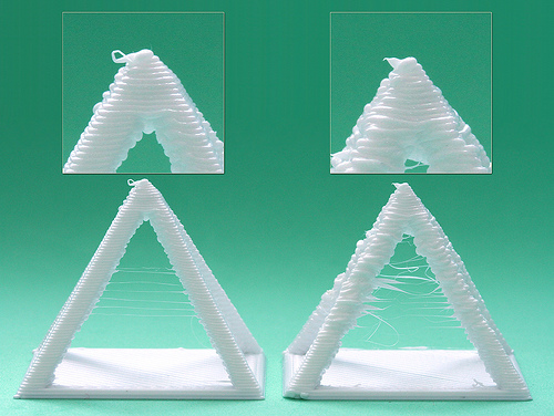
Ways of fastening the workpiece to the table
“Rafts”, “brims”, “skirts” – these terms sound funny, but they just refer to the three main ways of attaching a 3D printed part to a printer table. Let's take a look at each of these methods and their areas of application.
Skirt
The skirt involves creating a few rings around the object at the beginning of the print to make sure the plastic is extruded normally. The skirt is not in contact with the object at all. It surrounds the printable area and helps start the fusing process. When creating a skirt, a large volume of hot thermoplastic polymer passes through the nozzle. This prepares the printer for printing the part itself. This guarantees good adhesion to the table and obtaining smooth surfaces of the object.
Brim
The brim is a wide, flat area connected to the main object as a support base (think of a brim of a hat).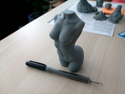 It is very similar to a skirt, but connected to the model. In addition to all the advantages of a skirt, the brim keeps the edges of the object being made on the table.
When printing, the outside of an object often cools faster than the middle, causing the edges to curl. Brim prevents this phenomenon by holding the edges.
Raft
A raft is a detachable base, made in the form of a thin mesh platform, located under the entire object (which lies on the raft). To create a raft, the printer first prints a flat plate in two or three layers, and then begins to manufacture the object.
The rafts provide excellent adhesion to the table surface and also provide a strong print base. This is especially useful when making small and oddly shaped parts that do not fit well on the table, as well as thin-walled objects.
After printing is completed, in most cases the raft will separate easily from the part.
If the printer does not have a heated desktop function
Rafts are used if the printer does not have desktop heating.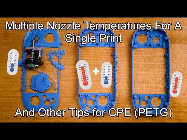 In this case, excessive adhesion becomes a problem.
An alternative method is to apply adhesive paper tape to the printer bed, with the edges down if possible (this also protects the bed). You can also use packing tape, but it is usually more expensive.
If buckling does occur or the object separates from the table, apply a dissolvable glue stick to the adhesive tape. This will enhance adhesion.
Find out the features of a specific 3D printer and take them into account when preparing a model
3D printing is not only a science, but also an art. Effective design for subsequent 3D printing requires an understanding of the technological process, taking into account its features and the purpose of the future object. This will greatly improve print performance.
Using Solid Edge in 3D printing
Not all CAD systems are suitable for 3D printing
The capabilities of the applied system should not limit the designers. Our Solid Edge system is designed with the latest 3D printing technologies in mind. Various 3D printers and 3D printing services are supported.
Take it to the next level with specific techniques for designing 3D printed parts
Generative modeling in Solid Edge opens up new possibilities: the designer selects a specific material, sets the design space, allowable loads, restrictions and target mass of the part, and the system automatically calculates the desired geometry. As a result, 3D printing methods can produce the most complex shapes.
In addition, when building models, the use of the results of three-dimensional scanning is provided. Solid Edge successfully combines the traditional boundary representation of solid models (B-Rep) and the representation of surfaces in the form of a grid of triangles, which avoids time-consuming transformations that are fraught with errors.
If you've already downloaded an STL file for printing, our unique synchronous technology makes it quick and easy to edit your imported models in Solid Edge in preparation for the process.
Printing with your own printer or submitting an order to a 3D printing service provider
Printing in Solid Edge on a local 3D printer is done using the 3D print command. Models can be saved in STL and 3MF formats, or sent directly to Microsoft 3D Builder. If you don't have your own 3D printer or need to try out different materials and surface finishes, Solid Edge allows you to directly submit your models to cloud-based 3D printing services (such as 3YOURMIND). You immediately receive quotes for the production of parts from various materials with its subsequent delivery directly to your door.
3D-CAD from Siemens from this article for 49900r (90% discount), the promotion is valid until March 20, 2020. Read more>>
Techno Print 3D Company
This is our first review of the most popular and inexpensive 3D printers for 2020. The list will include the best-selling devices in two price ranges (up to 30 tr and up to 60 tr). Printers working with both plastic filament (FDM) and photopolymers (LCD/DLP) will be presented. This list will always be up to date, as it is periodically updated and supplemented. Read more→
The Chinese company Dazz3D announces the launch of the project on KickStarter and accepts pre-orders for Dazz3D Basic and Dazz3D Pro 3D printers. These revolutionary new devices are aimed at both the professional and amateur markets. Read more→
We all know that precise calibration of the 3D printer desktop is the foundation and the key to successful printing on any FDM printer. In this article we will talk about the main and most popular ways to level the "bed". So, as mentioned above, 3D printing without desktop calibration is impossible. We face this process Read more→
It's hard to go through a day today without hearing about 3D printing technology, which is bursting into our lives at an incredible speed. More and more people around the world are becoming addicted to 3D printing technology as it becomes more accessible and cheaper every day. Now almost anyone can afford to buy a 3D printer, and with the help of Read more→
The FormLabs Form 2 and Ultimaker 3 are perhaps the most popular 3D printers today, capable of high quality printing with incredible surface detail.