3D print electrical connectors
Is It Possible to Produce 3D Printed Electrical Connectors?
Search
Search
Applications
3D Printed Electrical Connectors - Are We There Yet?
This post was written by Sr. Applications Engineer, Phil Lambert.
Numerous industries around us are in the midst of a movement towards electrification. An excellent example of this, and the one likely to have one of the highest impacts on the global market, is the passenger vehicle. Tesla and Cybertruck aside, major automobile manufacturers are contributing to the development of our electric vehicle (EV) future. Beyond that, automotive OEMs continue to introduce more computer systems, accessories, and other features that rely on electronic interconnectivity to function. Furthermore, new industries like delivery drones and autonomous robots continue to emerge, preparing to surpass the niche category label and enter into the mainstream global market. Widespread infrastructure will be required to support this approaching electrification, which will inevitably create similar growth in associated supporting markets.
As these market shifts continue, more players and products will emerge and electrical connector manufacturers will need to remain nimble to continue to support existing and new customers. OEMs like the four North American connector giants (TE Connectivity, Aptiv, Molex, and Amphenol) may be serving a market that is characterized by a wider range of products that are manufactured at smaller volumes. Electrical connector shells and housings are mostly an injection molded product. In the case of automotive injection molding, the most expensive part and longest lead time tend to be the manufacturing of the injection mold hard tooling. At high volumes, the cost of the tool is amortized over a large volume of parts and makes excellent economical sense. However, to make a similar part at small volumes, the costly tool can be expensive enough to make a small-batch product run not economically viable.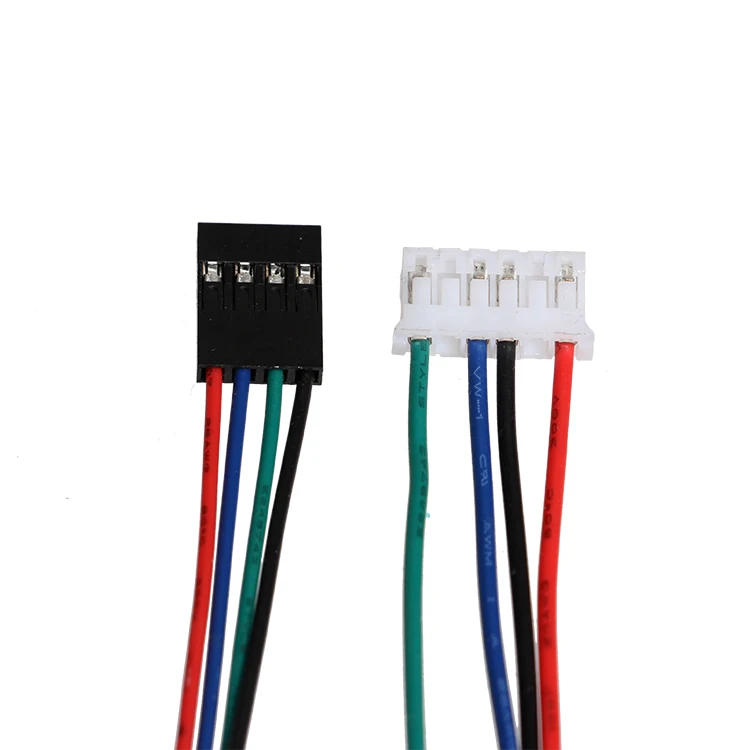 Most EV manufacturers are manufacturing less than 200,000 units per year, with more and more players entering this market. Finding new solutions will be essential to support the growth of these markets.
Fortify’s approach is modeled after fiber-reinforced injection molded plastic parts. Fiber reinforcement in a molded part shows a 20-100% increase in mechanical properties such as strength, stiffness, and HDT. This proven uptick in material performance is why the market for reinforced plastic parts continues to grow. Fortify is applying this same methodology to end-use manufacturing applications like electrical connectors. By adding reinforced fibers to the right materials during the printing process, Fortify can realize increases in electro-mechanical properties needed for high-performance parts while also meeting the economic requirements of small-volume manufacturing.
Small volumes and bespoke solutions are a perfect fit for 3D printing. Employing 3D printing can introduce both cost and lead time efficiencies.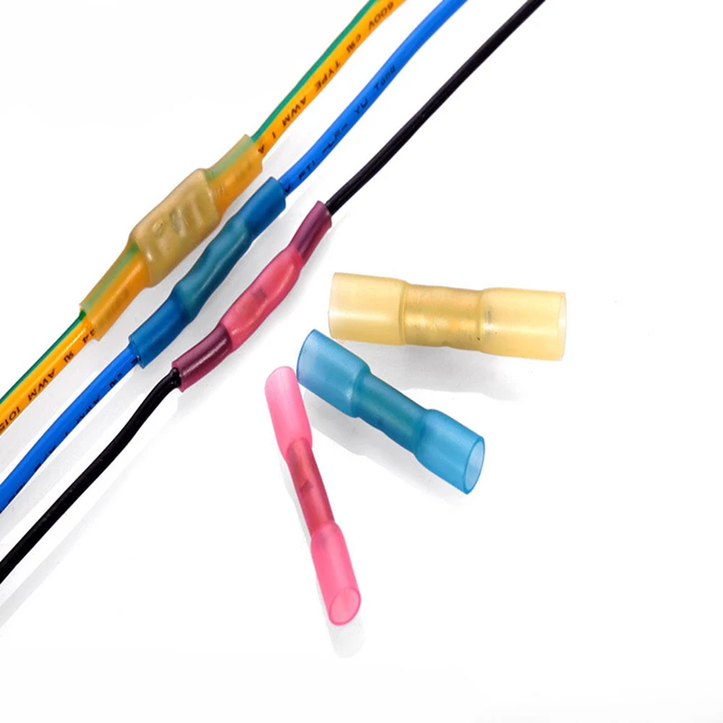 Smart and effective implementation of 3D printing on the factory floor will enable economically viable low-volume manufacturing runs and also shorten lead times by eliminating the need for tooling altogether.
The AM industry has started to engage with this product market fit. Collaborations with 3D printing companies and connector companies have started to see some real progress, however, challenges still remain. 3D printing OEMs are working to find THE breakthrough material + process combination that will eliminate the barrier to full AM adoption for production applications. What’s holding 3D printing back? In the case of electrical connectors, the culprit is a combination of material properties and print resolution.
Can 3D Printed Electrical Connectors Meet Auto Industry Standards?Looking closely at standard automotive electrical connectors, many housings and shells are made primarily from glass-filled engineering-grade thermoplastics like PBT, PPS, or nylon.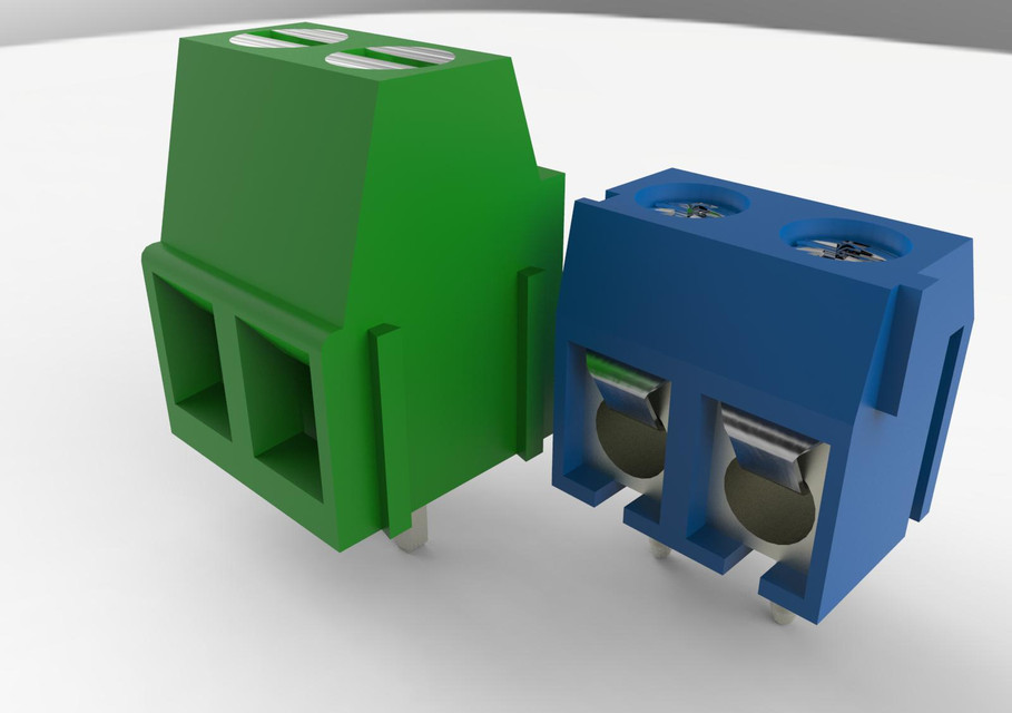 There are no players in the field who can directly 3D print PBT or PPS, but nylon has been available in 3D printing for decades – there are also glass-filled options available. For FDM and SLS, the two major commercial thermoplastic additive manufacturing technologies, there are severe limitations tied to the unavoidable physics of the technology. These processes cannot meet the resolution, surface finish, wall thickness, hole size, and tolerance requirements that are demanded of a commercial multi-cavity electrical connector. Some DLP and SLA solutions have the capability to reach these resolution requirements, but they can not print with industry-standard thermoplastic materials like nylon and PBT, or match their properties that are critical for this application.
There are DLP and SLA companies working hard to improve their resin formulations that come closer to the high-level requirements of electrical connector applications. The ability to print a part that is tough enough to survive several drops on concrete factory floors yet is also capable of surviving extended thermal cycling up to 150℃ is an engineering challenge for photopolymer material scientists.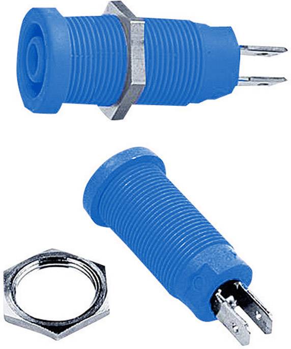 Achieving specific characteristics like high-temperature resistance combined with increased toughness can unlock access to big commercial opportunities for applications in aggressive environments – like in an engine compartment or areas exposed to dramatic weather conditions. Chemical manufacturers like BASF, DSM, and Henkel have developed high-temperature and V0 flammability rating engineering photopolymers with an eye on tackling the tough automotive electrical connector requirements, but a complete solution is not yet available. If our industry continues to focus on improving material properties in photocurable thermoset systems, we will be able to achieve both the resolution and material properties necessary for electrical connectors. Fortify is working with material partners to improve material performance for production parts, including electrical connectors, to meet automotive (and other industry) requirements.
Fortify Offers 3D Printed Electrical Connectors
With the global shift towards the electrification of high-value products, and continuous development of 3D printable materials teetering on the precipice of full engineering-level performance characteristics, the market is prepared for a solution. With continued collaboration between the 3D printing material developers and electrical connector OEMS, it won’t be long before we start to see real 3D printed solutions enter into this global market.
If you have an electrical connector application you would like to explore reach out to us for a quote today or learn more about our injection molding services for EV and auto manufacturers.
3D Printing Connectors - The Samtec Blog
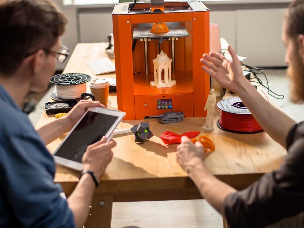
In a time of 3D printers in many engineers’ (and future engineers) shops, labs, or basements, we keep looking for ways to produce parts faster. You may be asking how far away are we from 3D printing connectors. When is Samtec going to replace all its automation with a bunch of shiny 3D printers? Can I get my parts faster if I make them myself?
As a director of a regional makerspace, we deal with 3D printers every day and get questions from every direction of “what can I make with a 3D printer right now!?” Our typical answer back is “what can’t you make?!” We then must frame up the speed, scale, and material options that are easily available to makers. If you are interested in a bit of history about 3D printing, check out this article by Sculpteo.
When I put my Samtec hat back on and think of new ways to produce parts, I tend to run into a few issues. At least issues with the full assembly. Prototyping and assembly support are a couple of ways we currently use 3D printing and additive manufacturing today. I will expand on each of those applications below and how Samtec can use alternative technologies to take care of our customers.
PrototypingChecking the form and fit of a component or feature in an application is typically a gateway into using 3d printing. The overall size and tolerance would be your starting point on the type of 3D printer you will need. Samtec will typically migrate to an SLA (Stereolithography) 3D printing technique for our connector development. This has always given us better resolution for insulator features and can typically handle very light assembly techniques to build initial samples.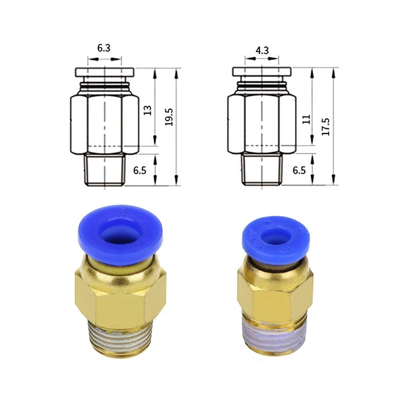 Typically, we cannot use these parts for functional test, but they can help prepare automation and marketing for what they need to do next. Some of our favorite vendors to work with are ProtoLabs and Xometry. They support 3D printing applications, as well as, many other advanced manufacturing techniques for prototypes and low volume builds.
We do not typically 3D print connector pins, but have dabbled with this process in the past. The problem with this is similar to the plastics. It can give you a form and fit, but not the function. Currently, available metals and alloys just do not have the same spring properties of traditional materials.
Tooling and Assembly Support
Over the years, Samtec has taken pride in the flexibility of our designs and engineering talents. Between 20%-30% of our business is making modifications of ASP’s (Altered Standard Products) for a specific customer need. With this style of business we need a flexible processes and tooling that can be manipulated on the fly. We have used plastic 3D Printed guides and fixtures to position assemblies in tooling. We have used 3D printed dies to create custom thermoformed plastic shells for packaging. Metal 3D printed components may be used for higher wear applications. We have found it helpful to evaluate a few different methods by working with a regional rep who carries multiple options. (One we have worked with on multiple occasions is Integrated Machinery System) Some metal tools we have been able to use right out of the machines, where others needed a bit of post processing.
We continue to keep our eyes on combining technologies, new materials, composites, and faster advanced manufacturing techniques. Every time we find something interesting, our automation and operations team step up and innovate. With Samtec’s speed, built in flexibility, and innovations on our website, we like to think we are keeping pace with the in-home replicators. If you have not ever used Samtec’s sample program, we can typically get you not only a representation of your assembly, but the actual fully functional assembly as a sample within 24 hours. If that is not fast enough to check your design, we have downloadable 3D models on most of our assemblies available instantly (supporting nearly 100 types of software and file formats).
Still Not Enough!
Do you need a larger volume faster? Many 3D printers can print multiple parts at the same time, but each addition adds time to the process. What about using optimized advanced manufacturing and logistics at their finest? Samtec Reserve™ is a new designation that we’ve provided on over 200,000 (and growing quickly) connectors and cables. These are popular stocked parts that are guaranteed to ship in 1-day!
Conclusion3D printing and other additive technologies are amazing and evolving how we build and design products. The speed of other advanced manufacturing techniques is also evolving. Where we can not fully 3d print a connector right now the utilization of 3D printing in the design and development process definitely speeds things up and helps us bring new solutions to you faster.
2 Story House
Candy & Food
Heart
Car
Useful articles and examples of 3D scanning
Partners
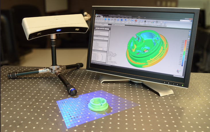
Technology: scanning, reverse engineering
Location: RangeVision Laboratory
Equipment: 3D scanner RangeVision PRO 5M
Software: ScanCenter, ScanMerge, CAD and GOM Inspect Free.
Time costs: scanning - 8 hours, scan processing - 4 hours, reverse engineering - 16 hours,
collection check - 2 hours, printing time 3 hours. 52m.
Auto electricians often have difficulty replacing electronic connectors that have broken during dismantling.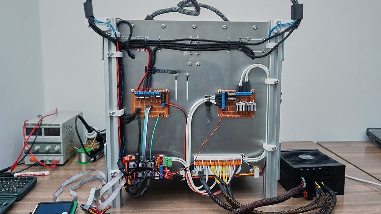 It is not always possible to purchase new ones - obsolete samples are discontinued. The use of 3D scanning, reverse engineering and additive technologies allows you to recreate the original CAD model and print an analogue.
ABS plastic, from which connectors for electronic devices are mass-produced, is similar in its properties to photopolymer - a material for 3d printing. Therefore, the company "Technologies in Volume" offered its customer, who is engaged in auto electronics, to print the details of the connector of the electronic control unit (ECU) of a car engine. The model of the restored Japanese car had long been discontinued, and it was impossible to order or purchase a part. But the Envisiontec Vector 3sp 3D printer, capable of layering models from durable and flexible plastic with high detail (up to 0.02 mm), lived up to expectations.
An electronic connector with small elements - sockets for wires and grooves - is a complex object for scanning, reverse engineering and printing.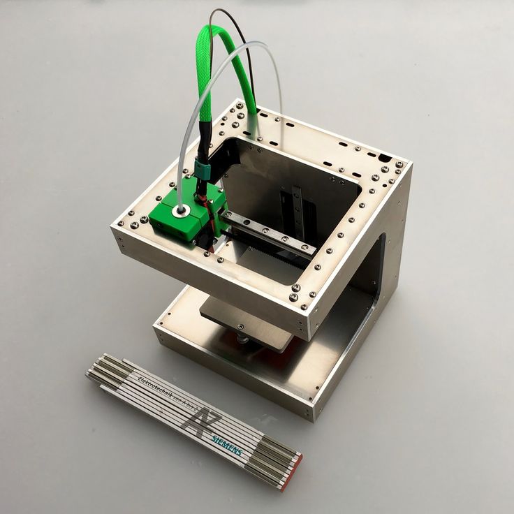 For example, the gap on the moving hook, which, when assembled, ensures the fixation of the wire, is only 50 microns. It was necessary to create three separate elements and ensure their collection. Using classical methods of measurement, without the use of specialized machines, it would be almost impossible to achieve the required accuracy of execution.
Before digitizing, the plastic parts of the connector were prepared - the wires and metal contacts were removed. The geometry of each of them was considered by the RangeVision Pro professional 3D scanner. First, the outer surfaces were scanned, then the side walls were removed with a clerical knife and the geometry of the hooks inside the cases was digitized. Scans of external and internal surfaces were connected and performed according to the obtained polygonal models of all three parts of the connector by reverse engineering, that is, CAD models were built.
In conclusion, we checked the assembleability of 3D models of connector elements. To do this, all parts of the electronic connector were virtually aligned in the working position, the gaps were analyzed and the fixation of the parts was checked with each other. Then they reproduced them on a 3D printer and made sure that they were actually assembled.
The customer supplied the plastic bases of the connector with all the necessary elements of the electrical circuit: contacts and wires. The new ECU will fully replace its mass-produced predecessor. The described method was the only solution to the problem.
↑
Thank you for your question!
Our manager will contact you shortly
Thank you for your application!
Our manager will contact you shortly
This site uses cookies. By clicking ACCEPT or by continuing to browse the site, you consent to their use. More.
3D Printer Quick Release Tools
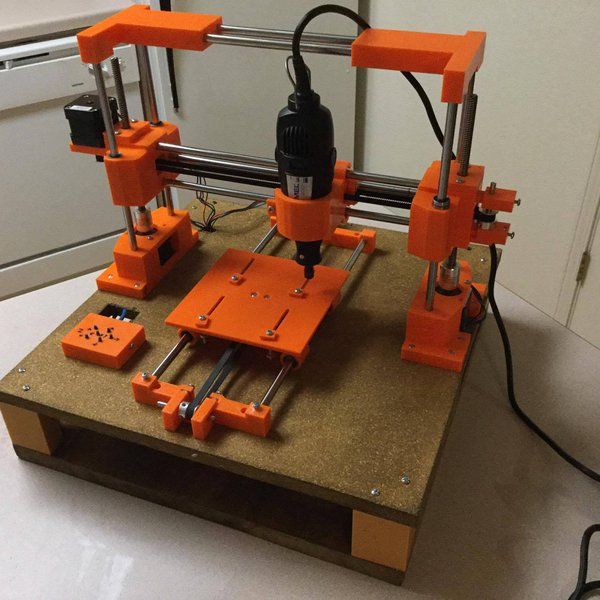
Sometimes a situation arises when you need to replace the hotend. For example, if the nozzle is clogged, but you need to urgently continue printing, or a different nozzle diameter / extruder type was required for printing. The option of implementing a quick replacement of the entire assembly with a printer tool was chosen. Also, this solution allows you to use the additional features of the printer and put a laser instead of a hotend or even a dremel. I want to share my implementation of attaching a hotend with a detachable connection for a relatively quick replacement of tools on the “head” of the printer. I have been using this solution on all my printers for about two years.
Currently available for the following tools:
1) Bowden E3D V6 (several options: 0.4 all-metal for ABS, 0.4 Teflon for PLA, 0.4 with steel nozzle for PET, 0.8 Volcano)
2) Direct E3D V6
3) Double bowden E3D V6
4) Laser diode (for cutting, engraving, lightening photoresist)
5) Dial indicator (for printer alignment)
6) Dremel (for drilling holes in printed circuit boards)
The base tool is mounted on two guide shafts and an electrical connector. The clamping is carried out with two M3 screws on the front side. As a result, fixing of other types had to be abandoned, since either sufficient pressure was not provided, or the weight and dimensions of the structure increased greatly, and for a 3D printer, the weight of the 'head' is a very critical parameter.
At the development stage, I had doubts whether the plastic would provide the necessary rigidity of the structure, because initially this assembly was made of an aluminum angle. After the first print, doubts were dispelled - the quality was not affected.
Printing examples can be found at the end of the article https://3dtoday.ru/blogs/chufyrin/3d-printer-with-a-fixed-table/
The design is based on the common nine-pin D-sub connector, which was previously present in PC (COM port), and now continues to be used in industry. It costs a penny and is easy to find at your local radio store. Current specifications suitable for most connector manufacturers: 5A per pin, wires up to 20AWG.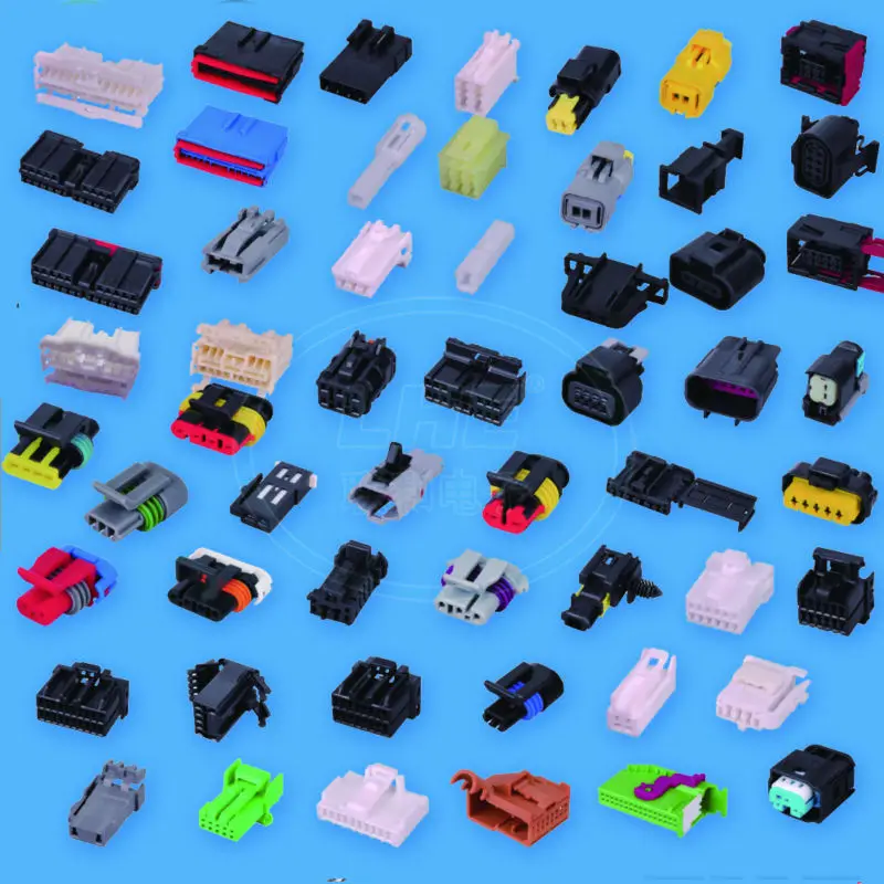 This is quite enough for the E3D V6 heater, which has a maximum current of about 3.3A at 12 volts of supply, and even less at 24 volts. This is in theory, in practice the connector does not heat up, the multimeter did not record the voltage drop at the connector. 9Ol000 8 - thermistor of the second hotend
9 - ground of the heater of the second hotend
The base can be with a built-in Z-probe, in this case another +5 volts, an optical limit switch signal and a PWM signal of the servo drive are started through the cable. Also, a signal from the X-axis limit switch comes to the base.
The laser diode is controlled by the part fan output, this circuit is supported by Marlin.
Power wires preferably flexible, such as PV-4 or wires in silicone insulation for modellers. I used speaker wires with very thin and soft strands.
In addition to the connector and M3 screws from non-printed parts, there are also two pieces of a shaft from a CD-ROM 2 cm long for precise positioning and secure fixing of the tool, 4 M3 nuts, 2 M3 screws for fixing the shafts and 4 M3 screws for attaching to the rail . In the next version, I plan to install brass bushings on the fixing shafts to increase the assembly/dismantling life, although the existing parts (bushings for plastic shafts) have worked for more than a year and there is no visible wear yet.
In this version, the mount is probably applicable to 3D-Sprinter printers. After some simple modifications, it can be applied to any other H-bot, Core-XY and plush-like printers.
Z-probe
Z-probe is optional and implemented on the optical end. The optical limit switch is blocked by a 3mm diameter cut shaft extracted from the same CD-ROM. When folded, the shaft is drawn into the structure. The shaft is pulled in by a servo using a thin thread (I used a piece of fishing line with a welded ball on the tip, but a regular thread will do). The thread is tied to the servo lever, and the end is simply applied to the shaft and wrapped with a 3mm strip of aluminum tape, the strip of tape also acts as a stopper.
Base, rear view
The shaft runs in brass bushings that are homemade from old hotend nozzles.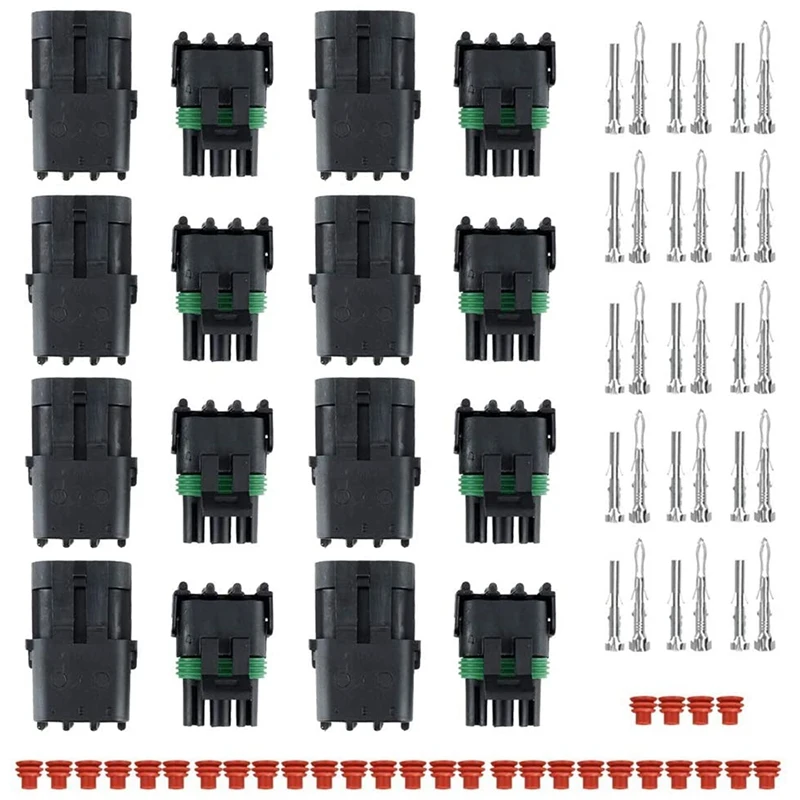 First, the nozzle is drilled through with a 3 mm drill, then a hexagon is cut with a hacksaw or a dremel with a cutting disc. The final touch - I cut the slot for a flat screwdriver with the same dremel or a hacksaw.
Making a sleeve
You will need 2 pieces. If the shaft eventually does not move freely inside the bushing, then you can drive it in the bushings with a screwdriver with the addition of GOI paste. To precisely position the bushings relative to each other in the plastic base piece, they can be heated directly or through a shaft and fitted with the shaft in place in the lightly melted plastic of the base piece. The shaft must 'fly' freely under its own weight through the bushings and at the same time not play. Tinkering for half an hour, you can easily achieve the desired result. Or go the simpler route: print the part without the bushings and rake the holes in the plastic to get the same effect.
Marlin Accuracy:
M48 Z-Probe Repeatability Test
Finished!
Mean: 0.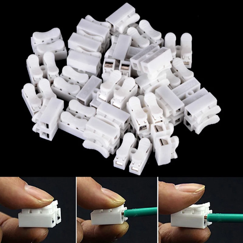 006875 Min: 0.006 Max: 0.012 Range: 0.006
Standard Deviation: 0.001875
I already wrote about this in an article about a printer with a fixed table.
Direct extruder
It's important to have a direct extruder when you want to print flexible materials, I use it when printing with TPU rod.
In the case of a direct extruder, the wiring to the stepper motor is supplied by a separate loop - it is switched from the bowden extruder motor. This is done so as not to make the cable heavier and not to install a second connector, which is not used in most cases.
Dremel
Installing a Dremel as a tool can be controversial for many printers. They will be able to mill only soft materials due to the insufficient rigidity of the printer. But I use such a tool for drilling holes in printed circuit boards. The circuit board has already been drilled decently and the printer has not yet broken a single drill.
Video of PCB drilling, 1mm and 0.3mm drills are used for vias (2 times faster) https://youtu.be/wdoe_wS5iAc
Last result after etching
Twin extruder
Twin extruder is still in alpha version. In my free time, I will refine it. The mechanism for raising an inactive hotend has not yet been implemented. With fixed hotends, printing requires a lot of towers and can leave defects on the printout.
Double extruder printing first version, improvements will be made
Slicer settings
The problem of different heights of hotends is solved by software. The solution was tested on the Marlin firmware. The slicer has a separate printer for each tool - a hotend. In addition to changing the nozzle diameter, the G-code for changing the offset along the Z axis is indicated before printing M206 Z. The offset is selected in the classical way with a piece of paper between the table and the nozzle.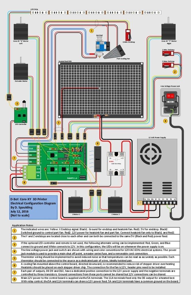
Please note that for this the following lines must be in the firmware settings:
#define min_software_endstops false
#define max_software_endstops false
Attention! Take care of the table, check without a hotend installed.
Read more here: https://airtripper.com/1799/marlin-firmware-home-offset-guide-using-g-code-m206/
The Z-probe version is even simpler, no firmware changes required, it is enough to set the hotend offset relative to the Z-probe trigger point at the start of printing with the M851 Z Y10 command.
Printable models
Base without Z-probe
http://chufyrin.hldns.ru/public/base-big-endstop-x.stl Base with Z-probe
http://chufyrin.hldns.ru/public/baze-z-probe-v-4.stl http://chufyrin.hldns.ru/public/baze-z-probe-v-4-1.stl Bowden e3d v6
http://chufyrin.hldns.ru/public/e3dv6-1.stlhttp://chufyrin.hldns.ru/public/e3dv6-2.stl Direct e3d v6
http://chufyrin.hldns.ru/public/direct-1.