Linuxcnc 3d printing
From 3D Printing to Machining Metal Parts
This article walks through the conversion of a g0704 mini mill to a CNC machine using LinuxCNC. I avoid the cost of a ballscrew conversion and instead use software backlash compensation with the stock ballscrews and am still able to achieve great results:
Way back in 2016, I got my first 3D printer and my eyes were open to the world of rapid manufacturing. The accessibility of information and tools for 3D printing are outstanding, in no small part to the founder of the open source 3D printer RepRap project, Dr. Adrian Bowyer.
After 4 years of learning to build 3D printers, designing new CAD models, and printing plastic parts, I decided it was time to make parts out of metal. Rapid manufacturing in metal is a fascinating topic, but is not nearly as accessible in terms of costs and publicly available information as plastic 3D printing. Therefore, I opted for a CNC milling machine.
Choosing a Machine
I spent a long time trying to figure out the best machine to buy. I looked at options from Tormach, littlemachineshop, Harbor Freight, and Sieg (the actual manufacturer of most mini-mills). In the end, the Tormach was too expensive, the benefit of a little machine shop over the Harbor Freight version was not worth it to me. I looked into getting a Sieg KX1-MACH, and would have chosen this, but importing it in the middle of the pandemic did not work out. If you're someone who does not want to build their own CNC, the Sieg KX1 seems like the best option. I really wanted an iKX1S-SIEG which has an option for a toolchanger, a faster spindle, and an enclosure, but the exclusive importer of these is Intelitek and they wouldn't sell me one. The folks at Sieg are very accessible, so if you are interested in this route, just email them directly.
In the end, I found and purchased a used Grizzly g0704 mill and South Bend lathe.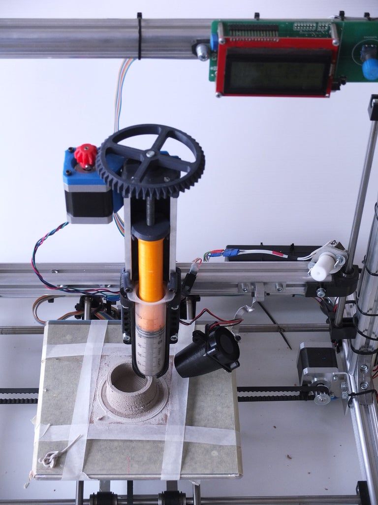 While the g0704 is just a re-branded Sieg machine, and way over-priced if purchased new, great deals can be found on a used machines.
They were a bit dirty when I picked them up.
They cleaned up nicely and I mounted them on a table made out of 8020 aluminum extrusion. Having both machines on the same sturdy table was very useful as their collective mass makes them more stable than if they were mounted somewhere separately. Adding mass to your machine, by a mounting configuration such as this or some other way, is a simple way to improve the precision of the machine. More mass reduces the potential for anything to move or vibrate during usage. A sturdy mounting of some sort is highly recommended.
Take note, the axes configuration on this machine, once converted to a CNC will be as described in the LinuxCNC User Guide, here are the axes are configured:
While this article is not about the lathe, it was very useful in making couplers for the mill, as I describe below.
Thanks
Thanks to everyone I talked to along the way. Notably, Chris at littlemachineshop.com, was very helpful, all the folks I talked to at siegind.com and Chris Li at Leadshine America who sold me the electronics as discussed below.
William McKnight at Carbide Depot was kind enough to supply a couple 1/4" carbide end mills, which I've been using to cut all types of material. They're so much more resilient than my high speed steel (HSS) tooling. You can see the end mill in action here. I'm cutting some steel inserts:
Hardware CNC Conversion
There are quite a few options to convert the manual g0704 to a CNC. The first choice is if one should use ballscrews or not. I decided to convert the machine without changing to ballscrews and use software backlash compensation, which turned out great.
Aside from being able to achieve great results without the cost of ballscrews, the main benefit of doing a leadscrew only (no ballscrew) conversion is that there is very little modification required to retrofit the g0704. The way I achieved this was by designing motor mounts that fit onto the existing mounts and couplers that fit over the nuts that hold the leadscrews on the x-axis and the y-axis, so permanent modification of the existing hardware for the leadscrew is required.
The two main things you'll need to make are the motor mounts and motor shaft couplers.
Leadscrew Motor Mounts
For the motor mounts, I started with the x and y axis:
I designed and 3D printed the y-axis mount, you can download the y-axis-mount.stl on thingiverse.
I cut the x-axis mount plate on the G0704 from 1/2" Aluminum stock by hand. The standoffs were cut to 2.10" (53.29mm), then drilled and tapped for M4 bolts.
Here is the x-axis drawing, if you would like to make your own:
I cut the z-axis last using the installed x-axis and y-axis cnc components. If you want to CNC the z-axis plate, the STL can be found on thingiverse. The reason this cannot be milled by hand is the center must be a circle.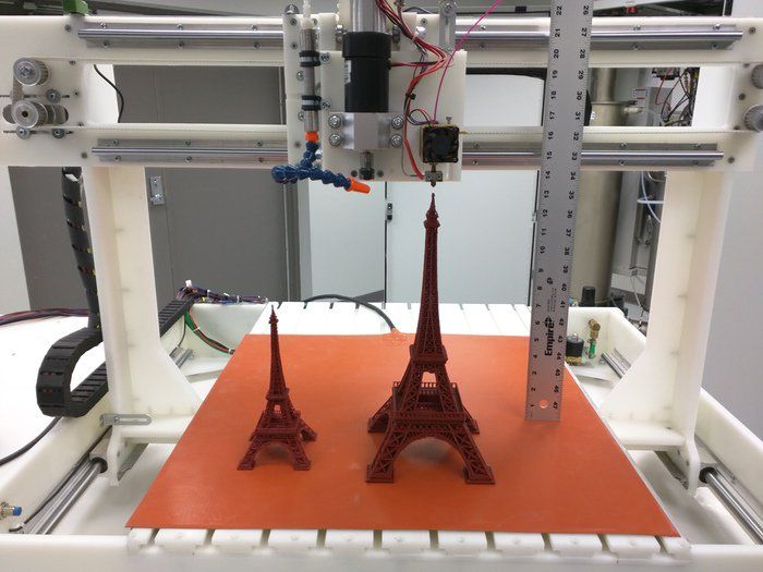 Standoffs were created the same way as the x-axis, but cut to 2.52" (64mm).
Here is the z-axis drawing:
Leadscrew Couplers
The x-axis coupler and y-axis coupler are the same. I designed them to replace the manual handle without modifying the other hardware on the axis, so the nut that would normally hold the handle in place, fits inside the coupler. Here is the original design:
In the final version, I decided to use 3mm rod to pin the couplers together to drive the shaft from the motor, instead of the 3x M3 set screws originally planned:
I made the couplers on the lathe, then drilled out the holes for the M3 pins on the mill.
The z-axis coupler is a simple fixed-shaft (solid) coupler:
Another Option: Ballscrews
The other option is to convert the lead screws to ballscrews. The drawings for the ballscrews are below, if you decide to go this route. You'll also need to actually modify the base of your g0704 as described in various places on the web, such as here: https://www. youtube.com/watch?v=wFzgrUe63xQ.
I have not checked these drawings myself, as I decided to use software backlash compensation, explained further below, instead of ballscrews, which made the conversion simpler.
Another option is to buy a kit such as: https://www.automationtechnologiesinc.com/products-page/g0704-bf20-pm25mv-x2-x3-kit/g0704-with-duf-ballscrew or https://www.heavymetalcnc.com/g0704/. However, these kits cost about $700, which is way more than I wanted to spend.
So far, I've been able to get great performance without ballscrews, as you can see from the video at the top of the page. The one downside is the head is not very heavy, so I have to take z-axis plunges quite slow to avoid the head riding up on the z-axis backlash. If I were to add a ballscrew, it would be for the z-axis, but don't see the need at this point and plan on just taking relatively slow plunge cuts.
Tooling
-
Collet Set for holding endmills. I got a full collet set, with my used mill purchase, but if you're just starting out, it may be better to pick a single size and just get the one or two collets you need.
 I use my 3/8" collet almost exclusively. If you're buying endmills, just buy them in the size that fits your collet, the shank size must match the collet, but the cutter size does not have to be the same as the collet.
 -
Drill Chuck I prefer a keyless chuck. The main consideration here is to get one that is not too tall to avoid having to bring the head way up before changing it! I actually bought a bit taller one that was cheaper, but I should have gotten the shorter one.
-
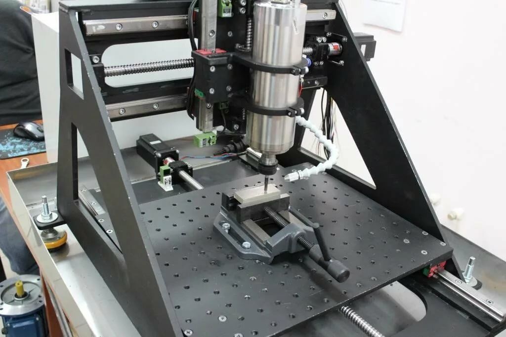
4" Precision Vise for work holding. A 4" vise is about the biggest you'll want and even this is a little big. I had to clamp mine down a bit creatively, since it does not fit well using the normal bolt cutouts -- it's a little too close to the back of the mill. Notice how I'm holding the vise in the photo below. Holding it this way works great.
Cutters
-
Endmills The best endmills to purchase will depend on the material you intend to work with. I suggest the material you start with aluminum or brass, which tend to be easier to work with "free machining" materials.
 For these, a set of two-flute High Speed Steel (HSS) cutters will do the trick. Remember to buy a set with a shank size matching your collet.
 -
Center Drills are necessary for starting (drilled) holes in the correct locations.
-
Drills are for drilling holes. You can use any drills, but a large set of HSS bits will ensure you have the right size for the job.
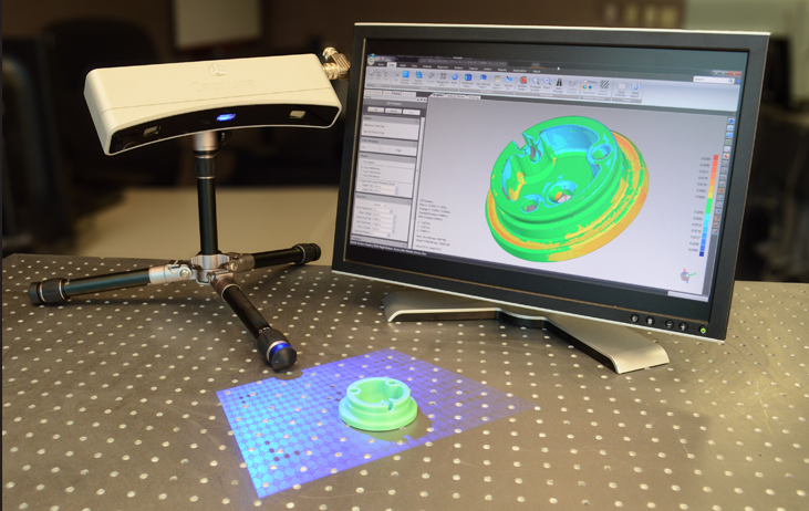
Measurement
Electronics
For CNC control, I'm using an old computer with a parallel port and a SainSmart 5 Axis CNC Breakout Board. SainSmart has a nice manual. Stepper online has their own version of the same manual as well. However, all of these manuals cover Mach4 and not LinuxCNC. This guide walks through the LinuxCNC setup in detail below.
Instead of buying from a Aliexpress or Amazon seller, I decided to get my electronics straight from a distributor. I think this is important so one gets a product that meets the specifications described in the manual. The distributor with the best product quality and price combination I found was Leadshine America.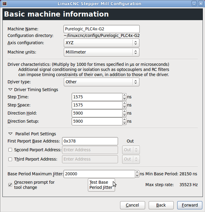 I'm using authentic Leadshine 4A stepper motors with DM556E drivers. I also bought a 48v, 10.5A power supply from Leadshine as well.
Here is the full electronics part list:
3x Stepper Motors: 57CM31-4A-I9 @ $49 each = $147
3x Stepper Drivers: DM556E @ $40 each = $120
1x 48V, 10.5A switching power supply: RPS4810 @ $55
Shipping was just over $20 and was quite fast, arrived from the west coast to my home on the east coast in only few days.
If you would like to order the same electronics I used, contact Chris Li at Leadshine America. Let him know you found him via this article. He did mention the power supply option, RPS4810, may be updated soon, so that might have a new model number if you order, but the rest should be the same.
I initially wanted larger motors, but Chris thought longer (more amperage) stepper motors would be too loud. It turns out these steppers work great and are nice and quiet for my use. Even running at full amperage, they stay nice and cool maxing out around 120 degrees Fahrenheit.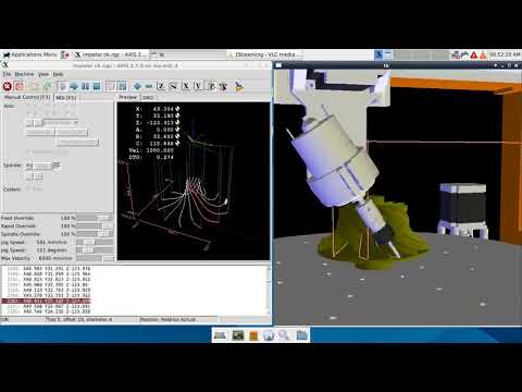
I also wanted steppers with a shaft that protrudes so I could attach a handle for manual motion. It turns out this is not necessary at all once the CNC is setup, and could actually cause a problem if manually moved, changing the zero point, so I am glad I got the version without the extended shaft.
I considered getting the more expensive DM556S stepper drivers, but am glad I went with the less expensive DM556E option that I chose, since this is more than sufficient for my use.
Wiring
First, some terminology.
The controller is the card that plugs into your parallel port on the computer.
The drivers connects to the controller and a stepper motor. There is one driver per stepper.
Controller to PC
You can use a parallel port cable if you have one. Since I don't a parallel port cable, I plugged the controller straight into the back of the PC. Since the USB cable no longer fits, I re-wired the cable by soldering it to the other side of the PCB. We only need to wire the USB cable's
 +5v and GND lines.
The board also needs 12v. For this, I tapped the yellow +12v line and black ground line from the computer power supply to the CD-ROM drive. I wired these to the parallel port adapter board.
Controller to driver connections
All the + control lines go to a +5v line
The DIR and PUL lines go to the same line on the correct axis. Note that on my controller, the PUL line is labeled CLK, which is fine, it does the same thing.
The ENA pin on the drivers all go to the same enable pin on the controller
Driver to motor
Using our wiring diagram for the motor, we see the correct connection by wire color
You'll also need to plug in your high-voltage supply
Driver Configuration
Here is a link to the full pdf manual for the Leadshine DM556E drivers.
The dip switches map to:
I set the RMS current to 3.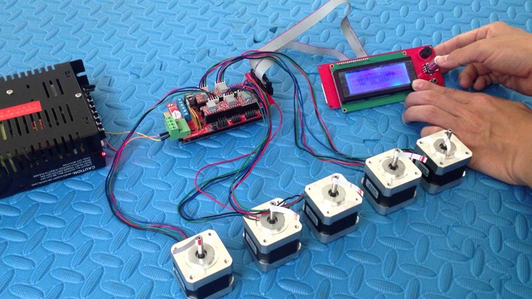 5A for the X and Y axis. The RMS current for the Z axis needed to be a little higher, so I set it to 4.0A:
I left the micro stepping setting to the default setting of 2: OFF, ON, ON, ON
Software: LinuxCNC
There are basically 2 options for controlling a CNC milling machine with a computer: LinuxCNC or Mach4/4. From everything I read, LinuxCNC is much more powerful and flexible. Plus it's free and open source, which is always a plus. The only constraint is that you'll need a computer with a parallel port or you'll need to buy an extension board. Cards from Mesa such as the 7I92M Anything I/O Ethernet card are a popular way to add a parallel port to new machine. If you choose to use Mach4 or Mach5, you can plugin the controller to any USB port. I'm using a computer with a built-in parallel port.
Installing Linux CNC
Look for the latest version available on http://www.linuxcnc.org/iso/linuxcnc-2.8.0-buster.iso
I'll be using what is currently the latest LinuxCNC 2. 8.0, Debian 10 ISO, which includes the realtime PREEMPT-RT kernel patch.
Burn the ISO to a USB stick. I used balenaEtcher on my Mac.
Install the Debian 10 distro from the USB stick. Detailed instructions can be found here: http://linuxcnc.org/docs/2.8/html/getting-started/getting-linuxcnc.html
Configuring and testing the parallel port
First, if you're using a computer with an onboard parallel port, enter the bios and make sure SPP mode is enabled.
Once you've got it connected and configured, run a test to make sure the parallel port is working by launching LinuxCNC and choosing the appropriate test port:
Use a multimeter in DC mode. Put the leads on the P2 pin and 5v pin. It should read ~5 volts. Click the Pin 02 button and the voltage should drop to 0. If this works, you're ready to move on.
Configuring the machine
Once you've got the OS installed, launch stepconf from a terminal or the Applications menu bar.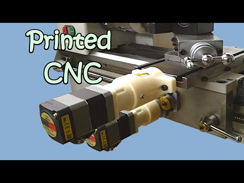
Create a new configuration, I'm using metric units, as most drawings I do are in metric.
Set the machine name, mine is set to g0704. Choose "Other" for the Driver type and use the Driver Timing Settings are from the table here. Search for DM556 and you'll find:
Step Time: 2500 Step Space: 2500 Direction Hold: 10000 Direciton Setup: 5000 Steps on: Rising Edge
Run the HAL Latency Test. Use the computer for a bit and then record the Max Jitter (ns) value.
Enter the max value and continue to the next screen.
For the parallel port config, set pin 14 to Amplifier Enable, matching the label of the pin on the board.
Recall we left the drivers set to the default microstepping value of 2 (switch 5-8: off,on,on,on), so leave this to 2 in the setup
For the X and Y Axis config, we'll compute the leadscrew pitch which is indicated on the g0704 handles as 0.1" per revolution. Converting this to mm/rev we get: 2.. I'm not sure how aggressive the default Maximum Velocity and Acceleration are at 25 and 750 respectively, so I'll turn these down to 10 until I get everything dialed in.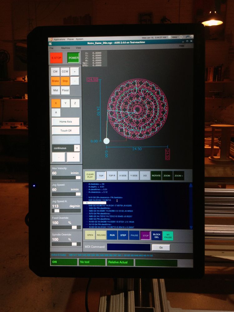 54 mm/rev
If you want to update the .ini configuration file later, the formula to convert this 2.54 mm/rev into "steps per user unit" used for the SCALE variable is described here http://linuxcnc.org/docs/html/config/stepper-quickstart.html#_mechanical_information and is as follows for my g0704 and motors:
STEPS_REV = 200 steps per revolution (equivalent to 360/1.8) MICROSTEPS = 2 microsteps per step LEADSCREW_PITCH = 2.54 mm per turn
Then scale is:
SCALE = STEPS_REV * MICROSTEPS * LEADSCREW_PITCH = 200 * 2 * (1/2.54) = 157.480314961
For the Z-Axis, the handle indicates 0.166" per revolution or 4.2164 mm/rev, so our Z-Axis scale is:
SCALE = STEPS_REV * MICROSTEPS * LEADSCREW_PITCH = 200 * 2 * (1/4.2164) = 94.867659615
Backlash Compensation
After ensuring your scale is correct, measure the backlash using a dial indicator.
Add this to the g0704.ini file under each axis. Also increase the axis joint's MAX_ACCEL value by 2x
Probing
I built a touch probe and touch plate for easier and more reliable setup.
Usage
I have setup my machine to be manually homed above the touchplate. To avoid a crash, be sure to home it such that the longest tool can travel down 50mm before contacting the touchplate! The tool will automatically move 50mm down before probing. This settings is further described below, but change the following parameter to change this behavior.
[TOOLSENSOR] ... # Absolute Z start search coordinates Z = -50 ...
With the probe in place and the machine homed above the touchplate, use the two remap M6 buttons on the probe screen to first probe the touchplate then probe the workpiece height.
With this done, probe the workpiece to set the G54 offsets and begin machining.
Even without limit switches, the machine can easily be kept homed between power cycles by homing the machine before turning off the machine and when the machine is re-powered on, simply set the home to the current position before moving the machine.
Probe Hardware
I built two probes, a tool setter and a touch probe. They are both normally closed and wired in parallel, so if either one triggers, the pin will go low.
Tool Setter
I don't have plans for the touch place, but it's basically just a microswitch bolted into a turned piece of aluminum round stock. There is a hole in the bottom so it can be bolted onto the table. I also placed a lightweight spring inside the mechanism to encourage the touch plate to move back up when not under pressure.
The touch plate diameter on the top is just under 20mm.
Touch Probe
I designed a mostly 3D printed touch probe. The design files and detailed build instructions are available on thingiverse.
It uses 6x 8mm bearings (actually 7.5mm diameter) in conjunction with 3x 4mm steel rods to create an exact-constraint mechanism. When the mechanism in capture, the circuit is complete. When the probe is moved slightly in any direction (including up), continuity is broken and the switch triggers.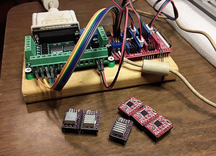
The small wires are held in place under the pressure of the bearing. Bearings are attached by a small m3 bolt into a drilled and tapped hole in the bearing.
The rods are press fit into the probe-tip holder in the middle.
Capture is encouraged using a spring.
Any size shaft and probe tip can be used. I used a 1/2" piece of steel rod I had laying around for the shaft and a small brass rod along with another ball bearing for the tip. This works well, but with such a large tip, probing any surface with less than 4mm height is not possible, so I will probably change this to use a small ruby tip in the near future.
The top of the probe is connected with 3x m3 bolts.
Wiring
Both probes are wired in parallel, as shown below.
There is also a connector for the touch probe, so it can be removed if necessary, while maintaining continuity for the tool setter.
Probing Setup
Configure the HAL, one wire of my probe is plugged into pin 15 and the other wire to the nearby ground.
Configure the HAL as follows:
net probe-in <= parport.0.pin-15-in net probe-in => motion.probe-input
Install probe screen v2
Comment out the bottom of the hal file, replacing them with the single line config for probe screen:
Comment out:
#loadusr -W hal_manualtoolchange #net tool-change iocontrol.0.tool-change => hal_manualtoolchange.change #net tool-changed iocontrol.0.tool-changed <= hal_manualtoolchange.changed #net tool-number iocontrol.0.tool-prep-number => hal_manualtoolchange.number #net tool-prepare-loopback iocontrol.0.tool-prepare => iocontrol.0.tool-prepared
Add:
net tool-prep-loop iocontrol.0.tool-prepare => iocontrol.0.tool-prepared
Download and unzip:
curl -L https://github.com/kiall/probe_screen_v2/archive/linuxcnc-2.8.zip -o linuxcnc-2.8.zip sudo apt install -y unzip unzip linuxcnc-2.8.zip cd probe_screen_v2-linuxcnc-2.8/
Copy the configs into your machine configuration directory, my config directory is ~/Desktop/g0704
cp -r python ~/Desktop/g0704/ cp -r macros ~/Desktop/g0704/ cp -r probe_icons ~/Desktop/g0704/
Install the plugin by adding the following in the [DISPLAY] section of the . config file: ini
ini
EMBED_TAB_NAME=Probe Screen EMBED_TAB_LOCATION = ntb_user_tabs EMBED_TAB_COMMAND = gladevcp -x {XID} -u python/probe_screen.py probe_icons/probe_screen.glade Configure the plugin by adding this to the bottom of the .ini file and modifying as necessary. Take care to merge any sections that already exist, such as RS274NGC:
[TOOLSENSOR] # Absolute coordinates of the toolsetter pad X = 0.001 Y = 0.001 # Absolute Z start search coordinates Z = -50 # Maximum search distance and direction (sign) MAXPROBE = -170 # Speed of movements during working in Probe Screen RAPID_SPEED = 240 # Diameter of toolsetter pad TS_DIAMETER = 19 # The speed of the reverse rotation of the spindle when measuring the tool diameter REV_ROTATION_SPEED = 300 [CHANGE_POSITION] # Abs coordinates tool change point X = -20 Y = -20 Z = -10 [RS274NGC] PARAMETER_FILE = linuxcnc.var RETAIN_G43 = 0 INI_VARS = 1 HAL_PIN_VARS = 1 SUBROUTINE_PATH = macros REMAP=M6 modalgroup=6 prolog=change_prolog ngc=manual_change epilog=change_epilog [PYTHON] PATH_PREPEND = ./python TOPLEVEL = python/toplevel.py
Note: that with this configuration the toolhead or probe will drop to Z = -50 (in absolute coordinates) before probing up to -170mm more. Make sure your tool is at least 50mm above the toolsetter or decrease this value!
More user documentation for probe screen v2 can be found here: https://vers.by/en/blog/useful-articles/probe-screen
Fusion360
I use the Fusion360 Manufacturing tools for my CNC toolpath planning and code generation. The included LinuxCNC post processor works great:
Machinekit Blog: Slicing for LinuxCNC
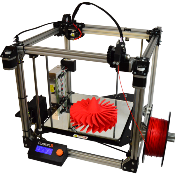
With LinuxCNC running my 3D printer, I have had to tweak my slicing settings to get good results. I normally use Slic3r, but Johann uses KISSlicer, so I tried both.
EXTRUDER WARNING
If you are printing with LinuxCNC, it is important to note that homing is completely different than with typical Arduino firmware. This is partly because the Arduino firmware essentially ignored decades of standardized gcode prior art, and partly because controllers like LinuxCNC have multiple coordinate systems (machine, world, part, and joint coordinates, for instance) which are generally all swept into "world" coordinates in most 3D printers.
Anyway, the auto-homing typically inserted at the start of a gcode file generally won't do what you expect, so it is important to make sure you have manually homed the X, Y, and Z axis before your first print, and REHOME THE EXTRUDER AXIS to zero just before printing anything! If you do not home the extruder axis, the first thing that will happen when you start your print is your extruder will try to 'unwind' all the filament it has extracted and end up ejecting the filament out of the extruder, and you will get to start over again. I am looking into fixing this with gcode remapping, incremental coordinates, or some other solution, but for now just remember to re-home the A (extruder) axis before each print!
KISSlicer
My issues with KISSlicer mostly related to not having any familiarity with it.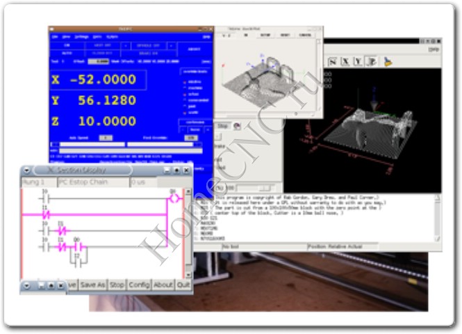 I started with Johann's Rostock config from the settings in his Kossel github repo (my printer uses 3mm filament and a 0.5mm nozzle like his Rostock). These slicing settings were reasonable, but I couldn't get gcode that worked for LinuxCNC (it still used E for the extruder axis instead of A). Finally, I found the "Axis" pull-down on the Printers -> Extruders tab, which let me set the axis to A. Using the "5D - Absolute E" firmware type setting, this got the axis setting fixed up. Temperature was still not working properly. M1xx parameters in RS274D/ISO 6983 require P and Q parameters, not S as used in Marlin and friends. This can be fixed in the Ptr G-code tab under Select Extruder. While there go ahead and fix the Deselect Extruder temperature setting, and add your personal prefix/postfix gcode.
Slic3r
I default to using Slic3r, which has a straight-forward Mach4/EMC gcode flavor setting under the printer settings tab. Despite having well tuned slic3r settings for this printer when I had it running via Marlin, I was having a terrible time with blobs and ooze. Nothing I did with the retraction settings or wipe seemed to fix the problem, although dialing up retraction did seem to help a bit.
It turns out the current version of slic3r (0.9.10b) forces a few settings if you select the Mach4/EMC gcode flavor. Essentially, selecting this gcode flavor forces retraction to be combined with subsequent travel in a g0 move, and disables wipe entirely. LinuxCNC performs coordinated g0 moves, so if the travel distance was very far, the retraction wasn't happening fast enough to avoid ooze no matter what I set it to. And wipe wasn't helping because it was being disabled by my selection of the Mach4/EMC gcode flavor. I made a small patch that fixes this issue and hopefully it will get resolved in a newer version.
Here's a print from slic3r with my 3mm filament/0.5mm nozzle with 0.2mm layers and 0.4mm infill:
Gone・Cults
Unfortunately, the job you are looking for has disappeared...
But don't panic!
Yes, this work is no more, it's sad. .. but you can always check the profile of the author schraubenonkel who made this model, or even send him a direct message.
Otherwise, at Cults, we always have something to please your 3D printer. For example, look at these little hooligans:
01
MCLAREN MP4/4 1:8 SCALE - FULLY PRINTED MODEL WITH INSIDE
12.50 €
02Cat skull mask ARTICULATED
6 € -34% 3.96 €
Fidget Gingerbread Man - Christmas keychain
2 €
04Road Runner
Free
05Santa Claus in a sleigh
3. 27 €
27 €
Christmas ball
Free
07TOC game, Toc game, DOG 9 game0012
3 € -25% 2.25 €
Homero
€2.99 -fifty% 1.49 €
Hammerhead Shark Articulated Toy, Printed Body, Snap Head, Cute Flexy
2.86 €
tenVase Triple S
Free
elevenInsect head attachment - Mason bee
10. 11 €
11 €
GOW: Ragnarok - stand for controller
6.32 €
13Halloween decoration - log head - Zanza
6.09 €
fourteenInfernal Dragon - Heaven and Hell
3.29 €
fifteenTravel chess pieces with magnets 6 mm
Free
16Dragon door knocker
2.40 €
17Off-road edition Lamborghini Aventador
35 €
eighteenCandle droid - with hinge and seal in place
2.40 €
19LITA
€14. 32
32
MODEL 4-stroke engine 110cc
14.41 €
which is better for prototyping?
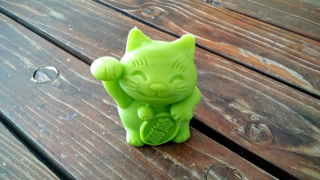
3D printing and CNC machining are more popular and affordable than ever. When you want to make a prototype, you decide what is best to use.
In this article, I will show you the strengths and weaknesses of each technology to help you make a decision.
Difference between 3D printing and CNC machining
The difference between 3D printing and CNC machining is that 3D printing is additive manufacturing while CNC is subtractive manufacturing. 3D printers have a nozzle that feeds layers of material to make parts, while CNC machining consists of a cutting tool that removes material to make parts.
CNC machines allow you to change the cutting tool according to the complexity of the application. As a result, CNC machines can be used to produce relatively more detailed products with high precision.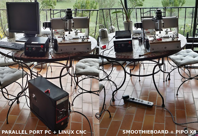
On the other hand, 3D printers are capable of creating complex shapes, making them ideal for rapid prototyping applications.
But is a 3D printer a CNC machine? Short answer: yes, it is a type of CNC machine that consists of a computer-controlled nozzle to print material.
However, 3D printing involves heating the working element, followed by cooling and solidification. This increases the total processing time required to manufacture the object.
In addition, there are many other differences that distinguish a 3D printer from a CNC machine.
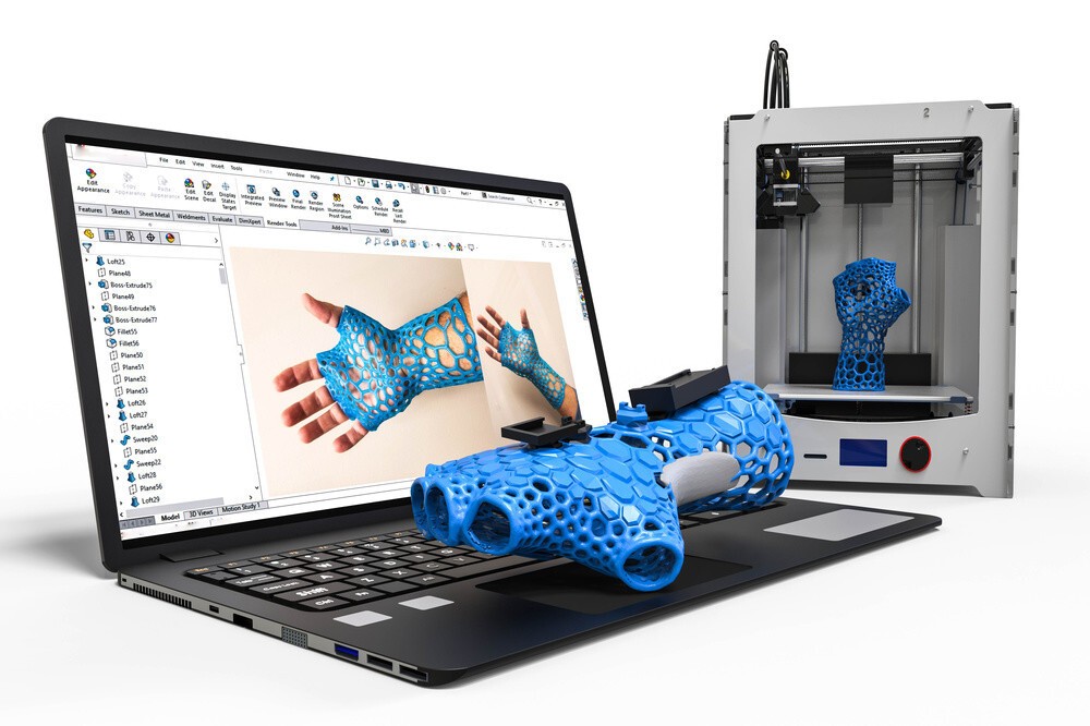
Workflow
When you look at CNC machines and 3D printers from a technical point of view, both of these machines are controlled by a computer.
Interestingly, 3D printers belong to the CNC additive manufacturing industry.
3D printers are a type of CNC machines.The CNC motion control system is responsible for moving the cutting head over the material.
In 3D printers, the cutting head has been replaced by a print head that applies material and a controller controls its movement to print the desired shape or object.
Like any other CNC machine, 3D printers also have a similar workflow. Differences arise in the production process.
A typical workflow for CNC machines and 3D printers includes:
- Designing a part model in CAD software,
- Creating a toolpath for CAD design using CAM software
- Checking the program file for errors using simulation software
- Correction of design or toolpath errors.
- Machining or printing a part.
CNC machines use CAD/CAM software to create designs and G-code files that are programmed into the machine for production.
Most 3D printing applications only require a 3D part design file to print. He then uses the CAM software to create a part program from the project.
The software used with 3D printers is similar to the CAM software used on CNC machines. They generate a G-code file used by CNC controllers.
Material Waste
CNC Metal Milling Material wastage in 3D printing is lower than in CNC machining.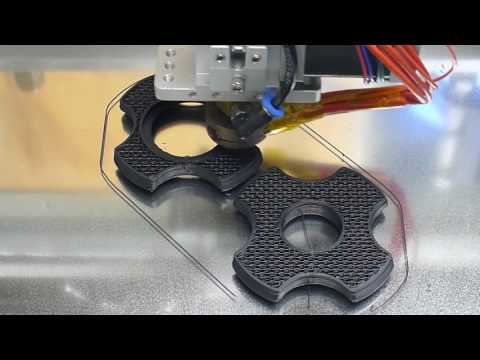 The main reason is that 3D printers only use the required material to create a part.
Because CNC machines use subtractive manufacturing techniques, they continuously cut out a block of material to give it the desired shape, resulting in a lot of material wastage.
Size and assembly
Compared to 3D printers, CNC machines are readily available in larger sizes. Making 3D printers more portable than CNC machines.
Most XXL-rated CNCs have a footprint of a few square meters, while large 3D printers can have a maximum footprint of 1 square meter.
For example, some of the giant 3D printing machines have a build volume close to 1500×1200mm. Whereas most industrial grade CNCs can have a working area of 3500 X 10,000 mm or more.
Because the CNC removes material from the workpiece by force, it must be of a rigid construction strong enough to withstand high cutting forces.
The rigid frame is one of the most important parts of a CNC machine. This is the frame that holds all the other components together. It also acts as a guide for the cutting tool and provides a precise path for the tool.
On the other hand, 3D printers use the material in a molten or powder form, which eliminates the need for a rigid structure to apply high forces during the printing process.
Additions
CNC CoolantDuring machining, these machines use certain additives to provide a suitable processing environment for the tool and material.
For example, the CNC uses cutting fluids to lubricate and cool the point of contact between the material and the tool. Sometimes they also require dust collectors to keep their working environment clean.
In the case of 3D printers, they use a heated platform to help adhere the object to the print surface.
Tools
VMC threading CNCs are versatile machines that allow you to change cutting tools to perform different types of cuts with different sizes and finishes.
3D printers lack this flexibility, and the printed object has the same resolution with a constant layer thickness throughout the print.
Accuracy and reproducibility
CNC machines can achieve higher precision than 3D printers because of the way they work.
The CNC machine's rigid frame provides high repeatability with minimal vibration, making it suitable for high volume production where multiple items with the same dimensional accuracy are required.
On the other hand, 3D printers melt and print material layer by layer, resulting in printed parts subject to slight dimensional inaccuracies.
Surface quality
3D printed plastic part (left) and CNC plastic part (right)CNC is better than 3D printed in terms of surface quality. This is due to the wide range of tools used by the CNC.
With various tools such as ball end mill, end mill, grinding belt, etc., the CNC can produce workpieces with high surface quality.
The layering process of 3D printers leaves behind a rough surface texture on the workpiece.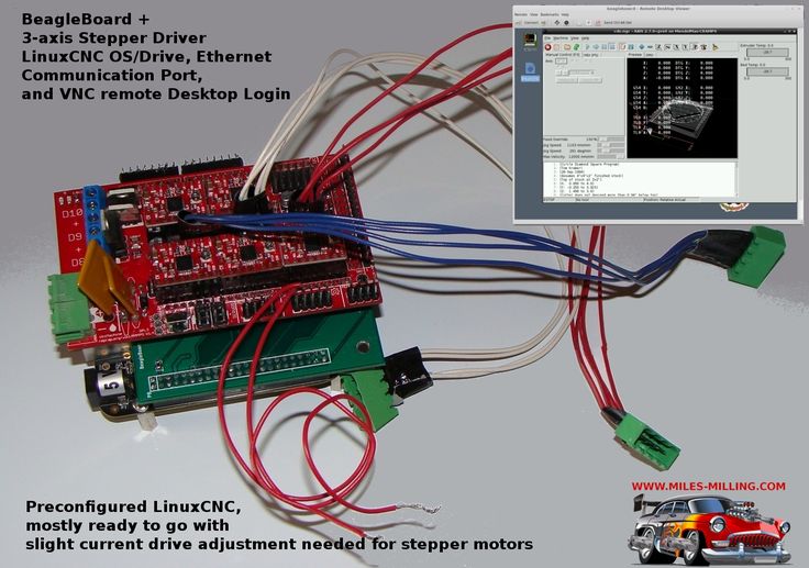
Today, 3D printed parts are treated with surface finishing methods such as painting, powder coating, electroplating, etc. to obtain a smooth surface.
Part strength and stability
Compared to 3D printing, CNC machining allows parts to be produced with tighter tolerances and greater strength.
CNC machines have a tolerance of ±0.025mm, while advanced 3D printing techniques such as direct metal laser sintering (DMLS) can only achieve a tolerance of around ±0.1mm.
In addition, because the CNC uses subtractive manufacturing techniques to make the part from a block of material, it does not lose the original strength of the material.
The 3D printer adds layers of material on top of each other that are fused together to form the final product. This reduces the overall strength of the part, making it prone to breakage.
The minimum line thickness that a modern 3D printer can achieve is 0.4 mm.
Costs
CNC machines are comparatively more expensive than a 3D printer with the same working area.
In addition, the need for various accessories such as coolant supply system, special cutting tools, etc., further increases the maintenance cost of CNC machines.
For small prototyping businesses, a 3D printer is a cost-effective option because it allows prototyping without the need for expensive equipment.
CNC and 3D printing - basics
Additive and subtractive manufacturing
Additive ManufacturingAdditive manufacturing is a technique that involves adding material layer by layer to produce a desired part or object. For example, 3D printers work on this principle.
This method is used for rapid prototyping of parts, production of complex parts and creation of customized products.
Subtractive ManufacturingThe subtractive manufacturing process removes material layer by layer from a blank block to create an object.
This is done with cutting tools and machines such as lathes, milling machines.
What is a CNC machine?
Various types of CNC machine CNC machine is a computer-controlled tool that can be used for various processing operations such as cutting, shaping and shaping various materials.
These machines usually have three axes of motion and can produce complex shapes from materials such as metal, wood, plastic, etc.
CNC technology has been used in manufacturing for decades. This allows machines to be programmed to perform complex operations automatically.
It is now an integral part of the production process in many industries and can be found in various types of machines.
Some of the common CNC machines include CNC milling machines, CNC lathes, laser cutters, plasma cutters, electrical discharge machines (EDM), grinders, etc.
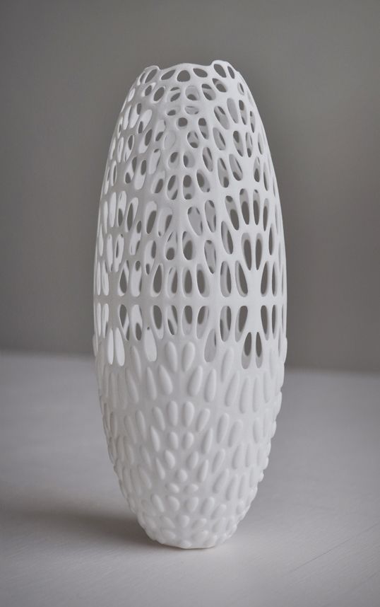
What is a 3D printer?
Vase 3D Printing on Snapmaker 2.03D printer is a type of automated machine that follows the principle of additive manufacturing and uses numerical control technology to produce the desired part from a CAD file.
These machines create 3D objects by laying down successive layers of material on a build plate until the object is complete.
The most common type of 3D printer is Fused Deposition Modeling (FDM) printers, which work by extruding thin filaments of heated plastic, metal, or other materials that cool and solidify after being deposited.
Practical application of 3D printing and CNC machining
Practical application of 3D printing and CNC machining depends on the material you plan to work with, the type of part you want to produce, the quantity and speed at which you want to make them.
The type of material you plan to use
The materials most commonly used for 3D printing are plastics, metals, and some biomaterials such as sugar or wood pulp.
3D printers can also use other materials such as ceramics and concrete, but these materials are less common because they take more time and effort to produce than plastics or metals.
By comparison, CNC machines can cut and mill almost any material.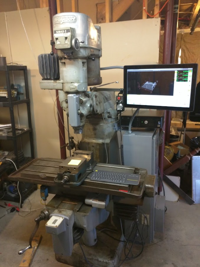 Some popular CNC machining materials are metals, wood, and plastics.
The materials that a CNC machine can cut depend on the design of the machine and the type of cutting tool installed in its cutting head.
Which is better for making metal parts?
CNC milling machine processes a metal workpiece. TheCNC machine is best for making metal parts because its rigid structure and transmission provide higher precision and accuracy than a 3D printer.
In addition, it allows the production of metal parts with higher tolerances compared to 3D printers.
What about plastic?
Both 3D printing and CNC machining are equally good for making plastic parts. The best option depends on the amount of detail you plan to make.
How many parts do you plan to make?
CNCs are better suited for machining large quantities of parts because they have higher repeatability.
If you are using a 3D printing technique to produce similar parts, it may be more expensive than CNC machining.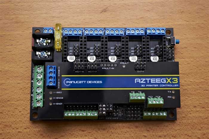
This is because 3D printers take more time and effort to complete a job, while CNC machines can produce many parts at once or in cycles with little effort.
3D printing is ideal for prototyping when fewer parts need to be produced (less than 10), whereas if you want to produce more parts, it is better to consider using a CNC machine.
For larger objects, consider CNC machining methods such as casting or injection molding as they are cost effective when producing parts in large quantities.
Which is better for prototyping?
While both 3D printers and CNC machines can produce custom parts or prototypes, 3D printers are much more efficient because they allow you to make multiple changes at a lower cost.
Therefore, various industries such as engineering, architecture, design and medicine use 3D printers for prototyping.
Will 3D printing replace CNC machines?
In a short period of existence, 3D printers have been able to partially replace the CNC used in the fields of medicine, architecture, product design, etc.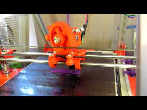
With its controlled deposition printing technology and the ability to create complex shapes, 3D printers are now increasingly being used to create architectural models and real structures.
Medical prostheses such as dental implants, orthopedics, etc. are now using 3D printers to produce various parts like never before.
These manufacturing shifts seen in these industries are a prime example of how 3D printers could replace CNC in the near future.
While 3D printers can replace CNC in many areas, they still cannot replace CNC when it comes to producing parts with high precision and tight tolerances.
In addition, the wide range of materials that the CNC can work with is a huge advantage of the CNC over 3D printers.
In short, CNC is here to stay. Although they have lost their importance in some industries, they are the most commonly used machines in the manufacturing industry.
It is difficult to say whether one will completely replace the other.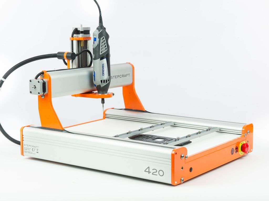 But in the future, they will be used together to create complex molds and prototypes.
In fact, CNC hybrid 3D printers are currently used in some industries.
Traditionally, printing and cutting were done on separate machines, but these hybrid printers or CNCs can do both tasks on the same machine.
Final thoughts - which is better?
Since the introduction of 3D printing into the manufacturing industry, it has taken over some of the work of CNC, but they could not take over all.
Much of the work is still done on CNC machines such as milling, turning, milling and grinding machines.
CNC and 3D printers are part of the puzzle. They both have their places, and both are needed to complete it.
They have different capabilities and can be used on different parts and objects for different applications.
Is CNC the same as 3D printing?
Technically yes, but functionally no. Like CNC, 3D printers are also computer controlled and work in a similar way, but CNC uses subtractive manufacturing methods while 3D printers use additive manufacturing.