What is jerk 3d printing
How to Get the Perfect Jerk & Acceleration Setting – 3D Printerly
You’ve tried countless solutions for your bad quality prints but nothing seems to be working. You’ve now stumbled upon these magical settings called the jerk and acceleration and think it might just help out. This is definitely a possibility and it has helped many people get high quality prints.
How do I get the perfect jerk & acceleration settings? Based on trial and error it’s been found that a jerk setting of 7 for the x and y-axis and an acceleration of 700 works very well for most 3D printers to solve printing issues. This is a good baseline to start from but it could take some tweaking on your 3D printer to get the settings perfect.
This is the short answer for your jerk and acceleration settings that should get you prepared. It’s a good idea to keep reading to learn some key information about these settings such as what they actually change, what problems they solve and more.
Whether you are looking for the best jerk and acceleration settings for an Ender 3 V2 or similar 3D printer, this should be a good starting point.
I wrote an article about 8 Ways to Speed Up Your 3D Prints Without Losing Quality which you can find useful for your 3D printing journey.
If you are interested in seeing some of the best tools and accessories for your 3D printers, you can find them easily by clicking here (Amazon).
What is the Acceleration Setting?
The Acceleration setting measures how fast your print head speeds up, limited by your designated 3D printer speed in your slicer settings.
The higher the setting, the quicker the print head will get to its maximum speed, the lower the setting, the slower the print head will get to its maximum speed.
A lot of times your top speeds won’t be reached when 3D printing, especially smaller objects because there is not much distance travelled to make full use of the acceleration.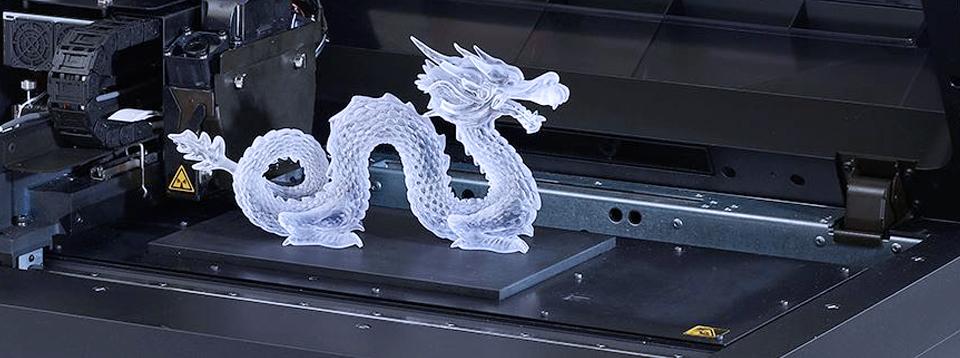
It’s very similar to a car’s acceleration, where if a car can go a maximum of 100 kph, but there are a lot of turns in your journey, you’ll find it hard to get to the maximum speed.
In the Cura slicer, they state that enabling ‘Acceleration Control’ can reduce printing time at the cost of print quality. What we can hopefully do on the other side is improve our Acceleration at the benefit of increasing print quality.
Your slicer doesn’t actually have much to do with acceleration, in so far as emitting G-code to say where the print head should go and at what speed. It’s the firmware which sets limits to speed and deciding how fast to accelerate to a given speed.
Each axis on your printer can have different speeds, acceleration and jerk settings. The X and Y axis settings are generally the same; otherwise your prints can have different features dependent on part orientation.
There are limits on how high you can set acceleration, especially when printing at angles larger than 45 degrees.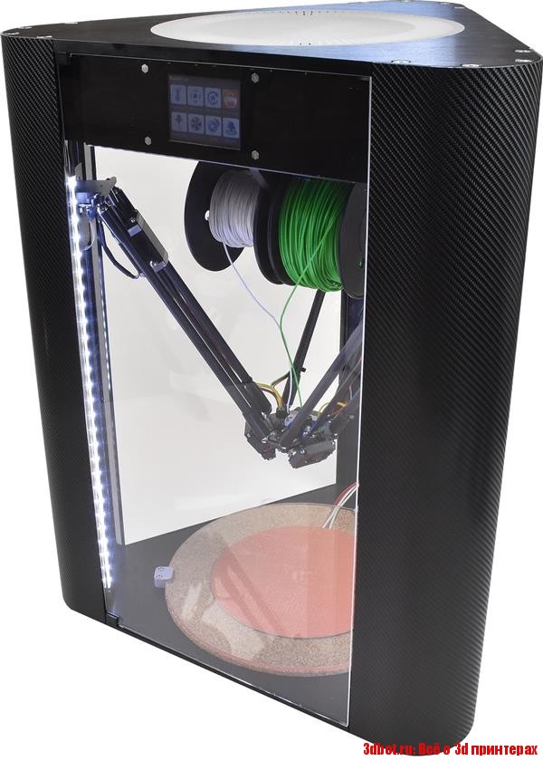
What is the Jerk Setting?
It’s quite a complex term and has different descriptions based on what firmware you are using. It’s basically an approximation value that specifies the minimum speed change that requires acceleration.
The Jerk setting measures the speed at which your print head moves from its still position. The higher the setting, the faster it will move off from a stable position, the lower the setting, the slower it will move off from a stable position.
It can also be known as the minimum speed your print head will slow down before initiating speed in a different direction. Think of it like a car driving straight, then slowing down before a turn.
If Jerk is high, your print head won’t slow down as much before making the directional change.
When the print head is told to change speed and direction in the G-code, if the difference in speed calculations is less than the specified Jerk value, it should happen ‘instantaneously’.
Higher Jerk values gives you:
- Reduced printing times
- Fewer blobs in your prints
- Increased vibrations from rapid changes in direction
- Smoother operation around corners and circles
Lower Jerk values gives you:
- Less mechanical stresses to your printer
- Smoother movements
- Better adhesion for your filament at direction changes
- Less noise from your printer
- Less lost steps as you may get with higher values
Akeric found that having a Jerk value of 10 gave the same printing time at 60mm/s speed as a Jerk value of 40. Only when he increased the printing speed past 60mm/s to around 90mm/s did the jerk value give real differences in printing times.
High values for Jerk settings basically mean the change of speed in each direction is too fast, which usually results in extra vibrations.
There is weight from the printer itself, as well as from the moving parts so a combination of weight and fast movement doesn’t go too well for print quality.
The negative print quality effects that you’ll see as a result of these vibrations are called ghosting or echoing. I’ve written a quick article on How to Solve Ghosting & How to Fix Banding/Ribbing which goes through similar points.
Which Problems Do Jerk & Acceleration Settings Solve?
Adjusting your acceleration and jerk settings has a whole host of issues that it solves, even things that were not known to you as an issue.
It can solve the following:
- Rough print surface
- Removing ringing from prints (curves)
- Can make your printer a lot quieter
- Eliminate the Z-wobble in prints
- Fixing the layer line skips
- Stop your printer from running too violently or shaking too much
- Many print quality issues in general
There are plenty of people who went and adjusted their acceleration and jerk settings and got some of the best print quality they’ve ever had. Sometimes you don’t even realize how good your print quality can be until you actually get it for the first time.
I’d definitely recommend trying this fix out and seeing if it works for you. The worst thing that can happen is it doesn’t work and you just change your settings back, but with some trial and error you should be able to reduce issues and increase print quality.
The video below by The 3D Print General goes into the effects Jerk & Acceleration settings have on print quality.
How Do I Get the Perfect Acceleration & Jerk Settings?
There are certain configurations which are tried and tested in the 3D printing world. This is great because it means you have to do very little testing to get the best settings for yourself.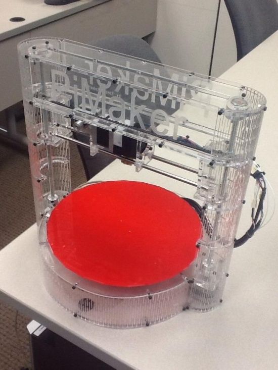
You can use these settings as a baseline, isolate either acceleration or jerk, then increase or decrease it little by little until you get your desired quality.
Now for the settings.
For your Jerk setting you should try 7mm/s and see how it goes.
Jerk X & Y should be at 7. Acceleration for X, Y, Z should be set to 700.
You can go directly into your menu on your printer, select the control setting, then ‘motion’ you should see your acceleration and jerk settings.
- Vx – 7
- Vy – 7
- Vz – can be left alone
- Amax X – 700
- Amax Y – 700
- Amax Z – can be left alone
If you would rather do it in your slicer, Cura allows you to change these values without going into your firmware or control screen.
You’ll just have to go into Cura settings and click advanced settings, or custom settings to view your Cura jerk and acceleration values. It’s similar in PrusaSlicer, but the settings are in the “Printer Settings” tab.
Usually you want to do this one by one. It’s good to start off with the jerk setting.
If lowering your jerk makes things too slow, you can up your print speed somewhat to compensate. If just lowering the jerk doesn’t fix your problem, then lower the acceleration and see what difference it makes.
Some people leave the Jerk settings at 0 & have an acceleration of 500 to get good prints. It really depends on your printer and how well-tuned and maintained it is.
Binary Search Method for Getting Good Jerk & Acceleration
The binary search algorithm is commonly used by computers to search programs and it can be used in many applications such as this one here. What it does it give a reliable calibration method by using ranges and averages.
How to use the binary method:
- Establish a value that is too low (L) and one that’s too high (H)
- Work out the middle value (M) of this range: (L+H) / 2
- Try printing at your M value and see the results
- If M is too high, use M as your new H value and vice versa if too low
- Repeat this until you get your desired result
It can take some time but once you find the settings that work best for your printer, it can make the world of a difference. You’ll be able to be proud of your prints and not have weird, wavy lines and artifacts plaguing your print quality.
It’s a good idea saving them as a default profile in your slicing software. So, the next time you come to slice your next print, it will be automatically input into the settings.
I advise you to write down what the settings were before you change it so you can always change it back in case it doesn’t work. If you forgot to it isn’t a big deal because there should be a default setting to make it go back to the original settings.
Jerk & Acceleration settings do vary from printer to printer because they have different designs, weights and so on. For example, 3D Printer Wiki says to set Jerk to 8 and the Acceleration to 800 for the Wanhao Duplicator i3.
Once you’ve tuned your settings, use this Ghosting Test to analyze the levels of ghosting and whether it’s better or worse.
You want to look for ghosting of sharp edges (on the letters, dimples and corners).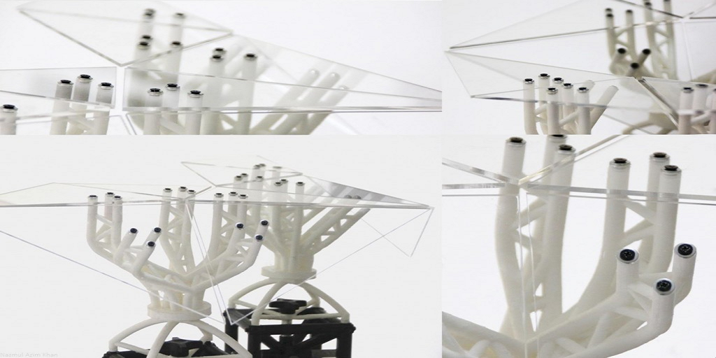
If you have vibrations on your Y-axis, it will be seen on the X side of the cube. If you have vibrations on your X-axis, it will be seen on the Y side of the cube.
Slowly test and adjust to get the settings just right.
Using Arc Welder to Improve 3D Printing Curves
There’s a Cura Marketplace Plugin called Arc Welder that you can use to improve printing quality when it comes to 3D printing curves and arcs specifically. Some 3D prints will have curves to them, which when sliced, translates into a series of G-Code commands.
3D printer movements are mainly made up of G0 & G1 movements which are a series of lines, but Arc Welder introduces G2 & G3 movements which are actual curves and arcs.
Not only does it benefit printing quality, but helps to reduce print imperfections like Ghosting/Ringing in your 3D models.
Here it looks when you install the plugin and restart Cura. Simply find the setting in Special Modes or by searching for “Arc Welder” and check the box.
It brings up a few other settings that you can adjust if needed, based mainly on improving quality or firmware settings, but defaults should work just fine.
Check out the video below for more details.
If you love great quality 3D prints, you’ll love the AMX3d Pro Grade 3D Printer Tool Kit from Amazon. It is a staple set of 3D printing tools that gives you everything you need to remove, clean & finish your 3D prints.
It gives you the ability to:
- Easily clean your 3D prints – 25-piece kit with 13 knife blades and 3 handles, long tweezers, needle nose pliers, and glue stick.
- Simply remove 3D prints – stop damaging your 3D prints by using one of the 3 specialized removal tools.
- Perfectly finish your 3D prints – the 3-piece, 6-tool precision scraper/pick/knife blade combo can get into small crevices to get a great finish.
- Become a 3D printing pro!
Before and after tuning acceleration/jerk : 3Dprinting
Before: http://imgur.com/JvzkfpK
After: http://imgur.com/8BIdkE8
Both at 0.05mm layer height
I wanted to reduce the amount of chatter and vibration in my printer, especially when printing small things fast. I was amazed to see my effector can move so fast it becomes a blur, however print quality also becomes blurry. The jerk values in the Marlin firmware are largely responsible for this. Jerk is almost like the minimum speed the printer is allowed to do, instead of smoothly building up to speed it does 100% power for a small "jerk" right at the beginning to get the print head moving. This makes corners sharper especially on heavy printers, but when printing small and precise things it often causes the printer to not be able to move slow enough to really get the detail needed.
Higher jerk values are good for heavier printers because they need an extra bump to get going, however I have a Delta printer with a relatively light effector end so having the same jerk value as a heavier printer was causing a big loss in precision. I wanted to completely disable X/Y jerk all together by setting it to 0, which should theoretically mean very little vibration at the expense of very slightly longer print time on precise shapes (exactly as desired!) however it seems as if the firmware/hardware is expecting a small amount of jerk because setting to 0 results in the motors making strange noises. I slowly increased my jerk to 4mm/s which allows much higher quality without impacting performance.
And I thought that acceleration values could help too, but after some more experimentation I've found that it is best to have relatively fast acceleration because all printers can handle it, but reducing your top speed to keep quality. I tried going for low acceleration with a high top speed, which causes slower, high quality detail, yet still allows the printer to reach a high speed on straight sections.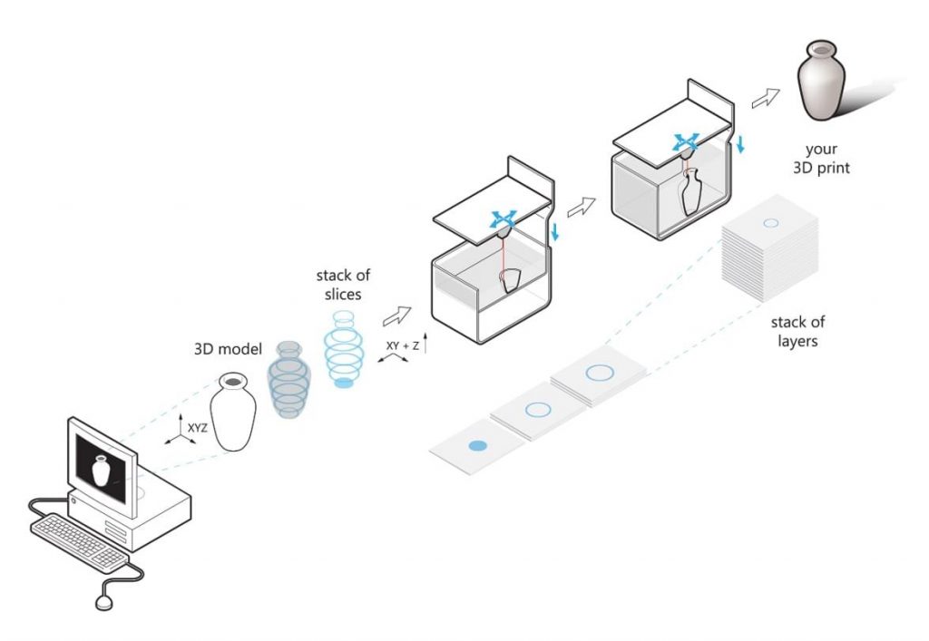 The problem was that my printer can only handle so high of a speed at all, going above that speed at any time results in massive stringing and vastly lowered precision and increased chances of stripped filament. Plus the low accel is handled badly by Marlin firmware, the motherboard only has 8-bit precision I believe so having a low accel and a high top speed "spreads out" the available resolution, leading to very audible "speed stepping" as the motors change their speed and causing a massive loss in high-precision detail and circle making ability. Plus the CPU on the board is running almost 100% as-is, it doesn't seem to be able to compute the moves fast enough with very low acceleration moves, this was partly remedied by lowering DELTA_SEGMENTS_PER_SECOND which reduces the sharpness to which the printer renders it's moves with. I lowered it to 100 which gave a noticable performance bump but did not visually affect quality.
edit: i have gained knowledge of the jerk. outcome is the same tho: lower jerk = better quality for slow/small prints
3D printing defects - Let's try to introduce classification
Good afternoon, dear visitors of the portal.
Today I decided not to go into the artistic part of our work, but again into the scientific one.
By coincidence, I graduated from the university with a degree in foundry engineering. Why am I mentioning this: firstly, for the last 10 years, the foundry has been threatened that it will die due to stamping and 3D printing. Secondly, foundry uses a lot of its own terminology. Today I want to try to describe the main defects in 3D printing, possible names and ways to deal with them (defects, not names). Of course, within the framework of one article on one portal, we will not introduce our own terminology, but at least there will be something to discuss. I invite you to read and adequately comment.
Defect : Warp
Commonly used description: Peel off platform, bend
Description : Geometry distortion. Due to the transition of plastic from one state to another (liquid - solid-liquid - solid) and temperature changes, the plastic begins to decrease in volume. This process is uneven - first the edges cool down, and then only the central part. Because of this, internal stresses arise that tear off the edges or break the part.
Now some physics and explanation. It is IMPOSSIBLE to get rid of thermal shrinkage or shrinkage. This is a physical process - you can only compensate for it. In addition, remember - shrinkage of 0.5 -0.9% is mentioned everywhere. But this is only linear, which means you will have more volume.
How to fight:
- Reduce fill - less plastic, less to shrink - less tear force.
- Use a hot table - you heat up the lower layers, which gives an even distribution of stresses inside the part.
- Outline - You can print an outer layer around the part. This creates a kind of thermal barrier around the part, thereby maintaining the temperature throughout the volume, resulting in an even distribution of stresses throughout the part. An alternative is a closed build chamber, serving in the same way
- Use structural elements - First, check that your part is lying well on the table - if your flat side of the part is not flat at all (in art it's easy - to move a couple of polygons or vertices to the wrong place on a couple of mm), then it will easily come off.
 Secondly, if you understand the physics of the process, you can either add material somewhere, or make a hole in the part, etc. In this way, you will artificially cause stress redistribution in the part, however, this method is extremely complicated.
 - Increase grip strength - you don't have to fight stress, just provide the required grip strength. However, this option does not seem very good to me - these stresses will remain and your part can then be easily broken in this place.
Defect : Skewed
Frequently used description: Layers floated, the vertical is not respected, the layers do not lie exactly on top of each other
Description: Several variants of this defect are possible. Either the layers just lie unevenly, or the model is printed somehow in pieces, or just a slight skew. This defect is usually associated with the mechanical part of the printer. Due to friction, the actual path of the print head does not match the one that was loaded into the machine.
How to fight:
- Check the belts. Since there are many designs, it is difficult to give a universal answer here. Check that they lie normally at the points of contact and are not frayed anywhere. Look at the printer's instructions or some tips on the Internet - it is quite possible that the problem has already been sorted out before you.
- If the printer simply shifts the layers relative to each other, then it is possible that the pulleys are not fixed properly. With a black marker, you can mark the position, and after printing, compare and tweak this place if necessary.
- Move the print head without power - it should move without significant problems. If this is not so, then maybe it is worth finally lubricating the shafts?
- Squareness not ensured - again, due to poor mounting, the X and Y axes may not be perpendicular. This can lead to this defect, which means it's time to climb into the printer again and twist.
- Check the print platform - the glass may start to slide on your printer.
 And just like that, in the same direction. In this case, it is necessary to ensure its fixation in some way.
 - Electronic problem. Rare case, but possible.
Defect : Boiling, Puffiness (?)
Common Description: Holes in top layer, problem with outer layer.
Description : Protrusions on the upper layer of the part - can be either open or closed. In fact, this is due to the sagging of the plastic, which does not have time to cool when printed in the air without supports. Considering that there can be several such layers and all of them are of poor quality, we get this defect.
How to fight:
- Provide cooling - your plastic should cool well on the top layer. According to the recommendations, at this stage, cooling should go as much as possible.
- Ensure sufficient layer and wall thickness - In addition to sufficient cooling, you must have the required number of layers.
 Again, according to the recommendations, your wall should consist of at least 6 layers of your thickness. Thus, when printing with a layer of 0.1 mm, you want your wall to be at least 0.6 mm. But remember - too thin base layers will not work either - they simply will not hold themselves and other layers.
 - Try changing the occupancy - some slicers change the occupancy configuration at a certain percentage of infill, so the difference can be even between 24% and 25%. In addition, with a larger fill, the distance that is printed in the air is smaller, which can also remove this defect.
Defect : Lack of layers (?)
Commonly used description: Round things do not come out round, parallel straight things do not come out parallel
Description : Sometimes the geometry of the layers is not observed - this can manifest itself in circles, when the circle is not perfect, as well as in parallel lines.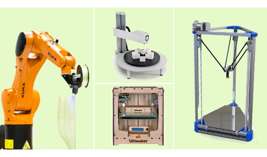 For example, parallel lines first diverge a little, and then, on the contrary, slightly overlap. This is due to the belts going to the stepper motors - most likely they are not fastened tightly enough.
How to deal:
- Tighten the straps near the print head - how to do this is best to look at the 3dtoday portal or ask your 3d printer supplier.
- Check that all fasteners are tight - use the tool that most likely came with your kit to do this
- Lubricate the guides - literally add one drop of light lubricant to your guides.
Defect : Elephant Leg
Commonly Used Description: Thick bottom layers, uneven layers at base.
Description : The effect when the bottom layers of your part are larger in area than they should be. Due to the fact that the nozzle at the beginning of printing is firmly pressed against the printing table at the beginning of printing, the layer begins to smear a little, thereby decreasing in thickness, but increasing in area. Then the print is evened out, because there is no longer a tight pressure
How to fight:
- Adjust the table - your nozzle should not rest against the print platform - there should be a slight, but still gap.
- Reduce the table temperature - a slight decrease in the table temperature can also reduce this defect. Do not get carried away with these methods too much - this may degrade the overall print quality.
- Structural model improvements - add small chamfers or fillets. You will have to play around with the settings a bit, but thanks to such a design improvement in the model, your model will be smooth and beautiful. However, it is impossible to say for sure which chamfer to make. Start with a 0.5 x 45 bevel, and then empirically find the best option.
Defect : External slack (?)
Common description: Snot, plastic between two parts part to another, a long, thin layer of plastic is created that spoils the outer shape of the part(s). This is due to the fact that the plastic that remains at the tip of the nozzle under the influence of gravity and friction is caught on one part and begins to drag through the air. Depending on the fluidity parameter and the hardening time, different plastics exhibit this defect in different ways.
How to fight:
- Use the retract function - thanks to it, the print head will slightly return the plastic, thus removing it from the tip of the nozzle. This setting is activated directly in the slicer (if it supports it). In the Cura slicer, the retract is drawn with thin blue lines and you can check this moment at the level of the finished task.
- Increase your print speed - the physics is simple - by increasing your print speed, you reduce the amount of time the plastic can catch on your part. However, increasing the print speed is not always possible and may cause other defects.
- Change the print temperature - print temperature has a direct effect on fluidity, especially with PLA.
 Reducing the temperature even by 10 degrees significantly reduces the effect of external sagging.
Defect : Waviness
Commonly used description: Discoloration at the edges of the part, defects along the edges
Description : This defect appears as darkening and slight waviness around the sharp ends. If you start typing the text, it will look like a slight shadow effect on it. This is due to the inertia that is imparted to the liquid plastic during printing. Regarding plastic, the print head has a large mass and during a sharp change in direction, liquid plastic is not able to sharply repeat the trajectory, which causes slight waviness in the corners.
How to deal with:
- Decrease print speed - Decreases print speed, reduces sharpness at corners, thereby smoothing the effect.
- Decrease print head acceleration - these settings are not available in all slicers, however, this will eliminate the defect without reducing the print speed.
- Change the print temperature - as we mentioned earlier, temperature affects fluidity, so lowering the print temperature can help get rid of the defect.
Defect : Looseness, Sagging (?)
Frequently used description: Snot on the part, sagging plastic on the part
Description: One of the most common and basic defects in plastic is due to printing in the air sags instead of getting a flat horizontal surface. This is due to the fact that the plastic does not have time to cool down and is printed without support where they are needed. Sagging can occur for many reasons, although the physical nature of the defect is practically unchanged. Because of this, the elimination of this defect may not be obvious.
How to fight:
- Cooling - Depending on the plastic, you may or may not need cooling. If it is necessary - provide it as much as possible.
- Print more than one part - for small parts, printing more than one part will help a lot.
 This will remove the heat source and give your part time to cool.
 - Work with the thickness of the layer - it is not possible to make a recommendation whether it is better to increase the layer or reduce it. Each situation must be decided, however, changing the thickness of the layer can improve or worsen the effect of sagging.
- Reduce print speed - very often reducing print speed can improve the quality of your part.
- Reduce temperature - if you decrease the temperature, the plastic will cool faster to a solid state. However, do not lower the temperature too low, otherwise the print quality may drop.
- Reposition the part - if possible without loss of quality, try to position the part differently. Stop, think, or use auto-positioning (like Meshmixer). Instead of fighting a defect, you can often simply eliminate it.
Defect : Layering of the bottom layer
Commonly used description: Clearly defined bottom layer, thick lines of the bottom layer
Description : Printing the bottom layer is one of the most important moments in printing.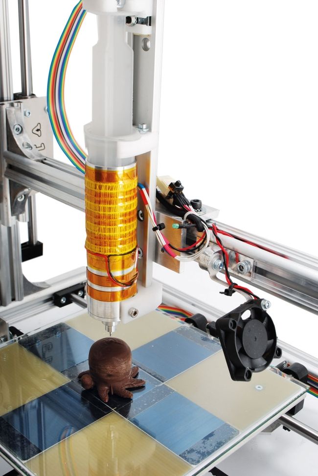 If we print too close, we will get an elephant leg defect. In the case of a large gap, we can get excessive layering of the lower layer.
How to deal with:
- Decrease the thickness of the first layer - many slicers have the ability to change the first layers of printing. Try to make it smaller to achieve a result that suits you.
- Recalibration - many problems with the bottom layers can be solved by recalibrating the table. Set the distance a little less and you might get the desired result.
Defect : Underextrusion
Common Description: Holes in Print, Layer Problems, Surface Defects
Description : Underextrusion is a defect worthy of its own article with a description. It can occur as a result of a huge number of factors, both related to the printer and plastic. It is very easy to observe it - the surface of the part comes out not even, but with all sorts of inclusions, or vice versa, the absence of plastic where it is needed. To eliminate this defect, an integrated approach may be required.
How to deal with:
- Change the speed - your printer may not technically be able to print at this speed. You may need to lubricate it or change the plastic, but first try printing at a slower speed. In addition, not all parts and not all plastics, the printer can print at maximum speed
- Change the temperature - all plastics have recommended temperatures for printing. If you print at the wrong temperature, then you do not provide the required fluidity parameters for working with this plastic and you will not print correctly with it.
- Check plastic - plastic may be damp, dirty or of poor quality. All this can lead to under extrusion, or that you will not print at all. In addition, plastic can break due to the feed mechanism and its strength properties. You may not be able to print with this plastic. Or maybe his diameter is walking .. As you understand, changing the plastic to another will allow you to quickly understand the problem in the printer or consumable.
- Check the paper feed mechanism - if you are working with soft plastic, the plastic may creased too much, which will prevent you from printing properly. Then, most likely, it will be necessary to loosen the grip of the bar, however, this should be done only after contacting those. support if you are doing this for the first time.
- Check the bar - during printing, sometimes your bar may become knotted or something is preventing it from entering the extruder. Be sure to check it out right now.
- Change or clean the nozzle - your nozzle will not last forever. In the course of work, it will become dirty - both from the soot of plastic, and from the dust that you allowed. Always have a pair of replacement nozzles available to help you understand this problem. In addition, when you refill plastic with a lower printing temperature, print at a high temperature so that the remnants of the old plastic completely come out and do not interfere with work.
- Check slicer settings - some slicers may use nozzle retraction and nozzle cleaning to get rid of external slack.
 Because of this, when you return the print head, you do not immediately start feeding plastic. This can lead to underextrusion in some parts of the model.
 - Check the Teflon tube - due to dirt allowed in the printing area, the Teflon tube may become contaminated. Because of this, the rod will experience friction, which will lead to underextrusion.
- Check the gears - if the gears that grip the bar do not work properly, then it will be problematic to exit the nozzle. If simpler measures do not suit you, check that this mechanism works correctly.
Defect : Notches (?)
Common description: Walls do not fuse together. Hollows in the walls.
Description: Mechanical problem. Due to the limited path of the printing part, there are voids and inconsistencies between the walls. Contact may be partial or absent entirely.
How to deal:
- Tighten the straps near the print head - how to do this is best to look at the 3dtoday portal or ask your 3d printer supplier.
 This option is best used in case of partial contact.
 - Reduce the print speed - plastic may not fit well at this speed. A slight increase in temperature may also help.
- Change the wall settings - this problem may arise due to the principle of laying this very wall. If you have a 0.3 nozzle, then it is impossible to lay a 1 mm wall in ideal layers of 0.3 mm. So the program can either represent the wall as 0.9mm and lay 3 layers, or somehow compensate for this. Try changing the wall thickness and maybe you can get rid of the defect.
Defect : Scratches
Commonly used description: Surface scratches and color unevenness
Description : During the movement of the surface, the print head leaves a mark on the plastic due to close contact with the plastic. This can be either grazing old plastic or smearing new plastic that flows out of the nozzle due to contact.
How to deal with:
- Increasing speed and decreasing temperature - as in other similar defects, when plastic leaves a mark, increasing speed and decreasing temperature can reduce the effect of this problem.
- Slicer setting change - To a large extent, this defect can be controlled by the slicer. Using Cura as an example, you can use the z-hop function (raises the nozzle). In addition, you can work on the retract.
- Change in geometry - this defect can still appear on complex surfaces. Try adding an even layer to your model or simplifying the geometry altogether if you're having this problem and it's making your life worse.
Defect : Underfill
Common Description: Part prints strangely. Incorrect entry of the part. Print supports where they shouldn't be
Description : The type of defects associated with the electronic model - can be associated with many things. If the polygons have incorrectly directed normals, if the model is not fully stitched (there are holes) or consists of several elements - all this can lead to this type of defects, when the slicer will misunderstand what they want from it.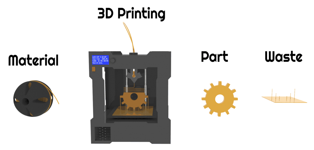
How to fight:
- Check the model in Netfabb/Meshmixer - with the help of specialized products you can check the model and see what errors it has. These programs eliminate many of the problems that were made before printing. However, these programs may distort your geometry.
- Fix the electronic model - if you have the skills and the ability to use the functionality of 3d programs to fix the mesh. Sew the meshes, close the gaps, reverse the normals, then check the resulting g-code. In it you will see how your model will be printed and whether everything suits you.
Defect : Fluffiness
Commonly used description: Model as in hair. Snot. Sagging.
Description : Reduced external sag. Small hairs stick out on the model, which remain from the printing nozzle. The physics of the phenomenon is the same, but the amount of plastic is much less. However, this defect can occur even if the nozzle does not move from one object to another.
How to fight:
- Check the plastic - your plastic may be dirty or poorly made. Try a different plastic and you may be able to get rid of the
- Check the nozzle - this fluffiness may be the first sign that something is wrong with the nozzle. Check the outside of the nozzle to make sure nothing is sticking out or try a different nozzle
- Remove the defect after work - this is the rare type of defect that is quite easy to get rid of by post-processing. Use a sandpaper, needle file or other handy tool.
Defect: Skipped layer
Common description: The layer is different from the other layers in the model. The model is flaking into pieces
Description: The case when one or more layers differ from the others. Then comes stable printing and the defect may recur. May be due to underextrusion or machine problems.
How to deal with:
- Familiarize yourself with underextrusion - it is possible that you will see more similar defects and you will know how to proceed.

- Lubricate the Z-track - since the table moves in the Z direction, it is possible that in some areas you have accumulated dirt or lack of lubrication. Lubricate the guide as recommended by the manufacturer and check operation.
- Bearing problem - it is possible that the problem is not in the guide, but in another element of the lifting mechanism. In this case, you need to check the bearing adjustment or return the printer for service. Look for more information on the portal 3dtoday
- Too much lubrication - too much lubricant - does not mean better. It can start to easily accumulate dirt and again begin to cause this effect. Wipe the shafts and lubricate with the necessary amount of material.
- Electronic problem - it is possible that the problem is not with the mechanical, but with the electronic part of the mechanism. If other methods do not help, then most likely the printer may need to be returned for repair.
- Defective parts - unfortunately this happens.
 It is possible that everything is done well, but some part of the mechanism is out of order. Again, this cannot be solved without disassembling the printer.
Defect: Misalignment of axes
Commonly used description: No right angle.
Description: Cases where the mating parts of the mechanism do not fit into the grooves due to misalignment. Another way to identify a problem is that the printer head moves with force.
How to fight:
- Editing axes - the defect is eliminated only mechanically. Ask the supplier or manufacturer for information on how to correct the axes and then reconfigure the printer.
I do not claim to be the final authority. For my part, I would like an adequate discussion and proposals in order to supplement and develop this article and formulate it into a finished version. Icons? mean that I still do not consider this name final and I expect other proposals for names from you. Only the names should be sensible so that a person imagines what it is and uses a short word to define it. It is better to mark grammatical and lexical errors in my personal - I hope we will agree with the editors so that they give the opportunity to correct the article. The material is based on this source. I did not specifically add some defects that are not related to the plastic, the printer and the printing mechanism (such as the detachment of the part from the table and the poor performance of the electronics), although you may say that it is more logical to add. In short, ready for discussion.
Sincerely, Sergey Panin
3D printing for the newest ones. From A to Z. Kinematics.
In this article, we will understand what 3D printing is and what the kinematics of 3D printers are.
1. 3D printing. What does she taste like?
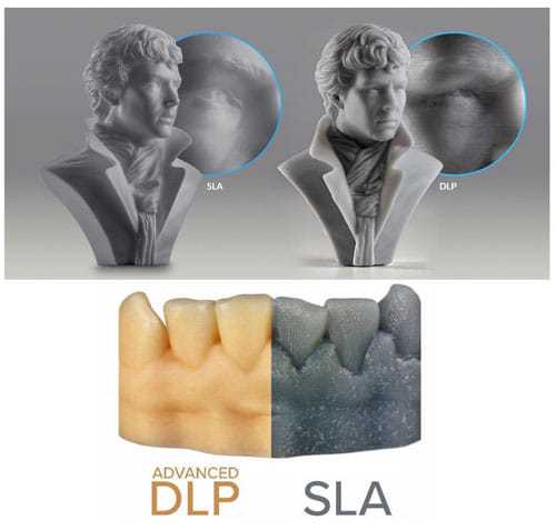
There are a lot of printing technologies, from FDM (FFF), which is used by more than 90% of printers on this portal, to SLA / DLP / LCD (with photopolymers) and SLS / SLM (powder sintering using powerful lasers)
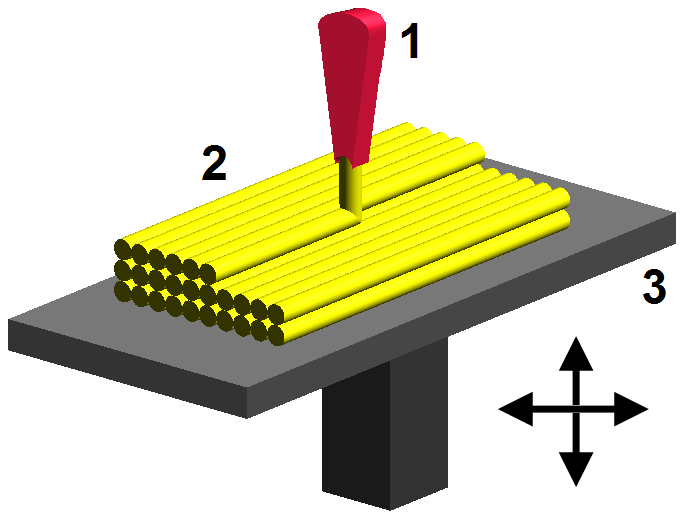
At the initial stage, we are interested in FDM - layer-by-layer deposition of a molten rod. The picture below shows the hot end (Hot end) - that part of the 3D printer extruder where the rod is melted.
The plastic rod is fed through the Teflon tube and radiator into the thermal barrier and through it into the heating block. It melts there and exits through the nozzle. The nozzle has a certain diameter, which is marked on it.
It is often made of brass, as the material is inexpensive and easy to process. The accuracy of printing depends on the nozzle. The smaller the nozzle, the more threads fit into one mm.
Heater and thermistor provide feedback for temperature control and regulation. That is, the voltage supply to the heater depends on what temperature the thermistor shows, and the processor compares it with the set one.
Next we see the heating block. A nozzle is screwed into it on one side, and a thermal barrier on the other.
The thermal barrier is used to minimize the heating of the plastic above the thermoblock.
[IMG]http://3d-makers.nethouse.ru/static/img/0000/0002/6151/26151635.2ofdbr37y8.W665.jpg[/IMG]
Most often made of stainless steel. It has a lower thermal conductivity than conventional, unalloyed steel. To prevent the rod from melting above the thermal block, a radiator is screwed on top of the thermal barrier and blown by a cooler. Everything is quite simple.
It is very common for melted plastic to leak through threads.
This means that the nozzle has not pressed the thermal barrier in the heater block. Therefore, when disassembling and assembling the hot end, we first screw the thermal barrier into the heating block, and then press it with a nozzle. If, when you twist the nozzle, there is a gap between the end of the nozzle and the heating block, then this is normal, the gap in order to press the thermal barrier with the nozzle.
In order to feed the bar at the right time and in the right place, a feeder is needed, that is, a bar feeder.
Sometimes it is performed combined with a hot end, and then this type of extruder (this is all together a hot end + feeder) is called a direct, that is, a direct feed, without tubes.
The same feeder is made separately, and the bar is fed through a fluoroplastic tube. Such a system is called bowden.
This is to lighten the moving part. As for the positive aspects and disadvantages - each design undoubtedly has them.
Direct extruder:
1. Advantages:
a) More reliable due to fewer plastic feed connections;
b) Less picky about the materials it prints on, in particular rubber-based rubber is problematic to print on bowden extruders;
2. Disadvantages:
b) Dimensions. They greatly affect the plot area. Let's say, like in the picture above, a direct with 4 colors would be very huge. And for Bowden, this is just right.
Bowden extruder:
1. Advantages:
b) The coil does not twitch after the model, otherwise, when the coil turns with the direct are entangled, we will get a skip of steps, since the carriage will pull the coil along with it.
2. Disadvantages:
a) Retract settings (pulling the rod back during idle movements so that the molten plastic does not ooze out of the nozzle expanding) is more difficult, since the rod is smaller than the inner diameter of the tube, it tends to stretch;
b) It is more difficult than on direct to select all gaps in order to print with various flexible plastics. Everyone who says that printing on Bowden is impossible with flexible plastics is blatantly lying. I am typing. And quite successfully.
Now we go directly to the mechanics and its calibration.
Part 2. Mechanics. What, how and what pulls?
There is a very limited number of kinematic schemes for which the firmware is written, and which work out movements quite tolerably.
Consider everything, from the most common:
1. Design and kinematics from Joseph Pryusha (no need to read Prus, Prasha and so on, this is the name of a person, after all).
Movement along each of the axes is provided by its own independent motor. Movement along the Z axis (up and down) is provided with the help of 2 motors and with the help of a kinematic screw-nut pair. M5 studs are often used; recently, screws with trapezoidal threads have been increasingly installed.
Here is a trapezoidal screw. How studs with metric threads look I will not apply.
The only thing I will explain about moving along the studs and trapeziums is that for the production of trapeziums they take a calibrated rod and roll it between rollers at an angle. Get helical grooves. This method, a priori, gives better quality and step accuracy than building studs of far from the highest quality.
To connect 2 motors to one axle (and 1 connector) at the same time, the following scheme is used.
Connection in series, 2 wires soldered and the rest crimped. You can ignore the colors, the main thing is that the windings ring. A and B are windings, and 1 and 2 are terminals.
Advantages of this kinematics:
1) Independent movement of each axis. It is easy to catch to understand which axis skips steps. Kinematics migrated to printers from CNC milling, so many manufacturers make desktop milling machines on it, instead of an extruder they offer to install a laser for engraving or cutting, a spindle for milling boards, an extruder for chocolate or even dough to bake pancakes.
Pictured above is a ZMorph printer. It can be used as a printer (with one or two extruders), as an engraver (Dremel machine), as an engraving laser, and so on. A small presentation video.
Milling machine with this kinematics. I note that for milling it is necessary to use a screw-nut pair to move, and not belts, they are not designed for such loads.
Chocolate and pancake printers according to your design. It is worth noting that it is not recommended to use chocolates like Alenka or Babaevsky, since they already contain cocoa butter and during processing (melting and hardening) the result is unpredictable. It is necessary to use chocolate in galettes, such as the Belgian Callebaut, as it does not contain cocoa butter, and must be added for the final filling. For this type of chocolate, each pack has a graph of its crystallization. It is desirable to take the oil in powder form. For more information, I recommend Google about tempering chocolate.
2) The kinematics are as easy as two fingers. Its very easy to assemble. Many even collect on old DVD drives.
3) Easily changed to suit your needs, the size of the extruder is also of little importance, as it protrudes forward and does not interfere with the movement of other parts. Many people put a second extruder, or make the nozzles swing so that the nozzles of one extruder do not remain on the part when printing with the second nozzle.
Therefore, for this kinematics, there are a huge number of extruder variations, for every taste, on a very famous site.
Disadvantages of this kinematics:
1) Complicated calibration. Yes, since the table 'jumps', it is difficult to print with high quality, because the part + table, with a sharp change in the direction of movement by inertia, tend to go further. Ugly print artifacts are obtained. And for high-quality printing, you need a small speed. In general, it all depends on the frame. My first printer was a Chinese pryusha. With acrylic frame.
Acrylic is not very hard. And as you know, the rigidity of the printer, like the CNC, is the most important thing. And it was possible to print more or less qualitatively at speeds of 40-50 mm / s. Then I transplanted it to a steel frame from MZTO.
And after that, without loss of print quality, I was able to print at speeds up to 100 mm / s.
2) Delamination. Due to the open case and the constantly moving platform, hot air, one might say, is constantly blown away, and by cooling the part excessively with drafts, we increase the already large shrinkage of nylons, abs and other capricious plastics. Someone sews a fur coat for a fabric printer, and someone is content with boxes.
But the goal, as always, is the same - to reduce the effect of drafts on the shrinkage of the part.
Key points for correct calibration of printers with this kinematics:
1) Place the printer on a level surface. Preferably horizontal. This requires a bubble level. Next, set the level of the position of the X axis.
2) Transfer to the home position. It is done either in the printer menu with the Home / Home command, if you are printing from a computer, then either with the G28 command in the command line, or with special buttons with the house icon.
Next, tighten the table screw so that the nozzle touches the glass. It did not press on the glass, but touched. We look at the light and twist. After that, move the extruder to another corner with the arrows in + X, + Y from the PC, or through menu
Turn the screw in the same way until it touches the nozzle. And repeat the operation for the remaining points.
I will try to save you from mistakes. In the photo of the printer above, the glass on the table is fastened with as many as 8 clamps. And it is quite possible that there will be a hump in the center. To avoid such problems, the glass should be fixed with 3 clamps. The plane is built, as is known from descriptive geometry, by 3 points. And calibration will be easier in this case. Just tighten the screw over the limit switch in Z.
For the nozzle to touch the glass in the middle of the side with 1 clip. Then we distill the hot end into the corner where there is another clamp, tighten the table screw, and repeat the operation with another angle.
Regarding wobble.
All sorts of anti-wobble systems such as installing a bearing in the upper support do not work.
Just because putting 4 far from perfectly even cylinders in perfect parallel and in the same plane is an unrealistic task. Especially on a flimsy acrylic frame with printed details. Therefore, if we take the straightness of the shafts as a constant, and set them parallel on the frame (purely hypothetically), and release the screws (from below the coupling for attaching to the motor) and nuts for attaching the X axis. Due to their curvature, the screws will spin like a mixer, but on printing will not be affected.
Otherwise, the design will work on who will be stronger in terms of bending resistance. And it will turn out far from a flat wall. Do you need it?
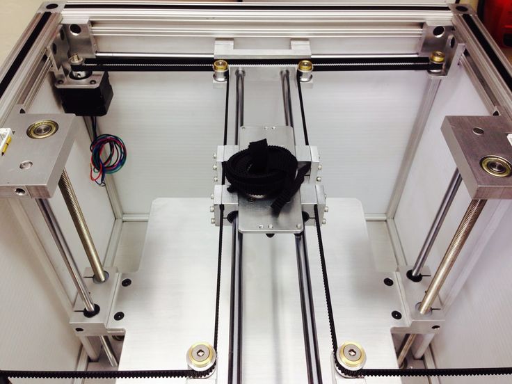
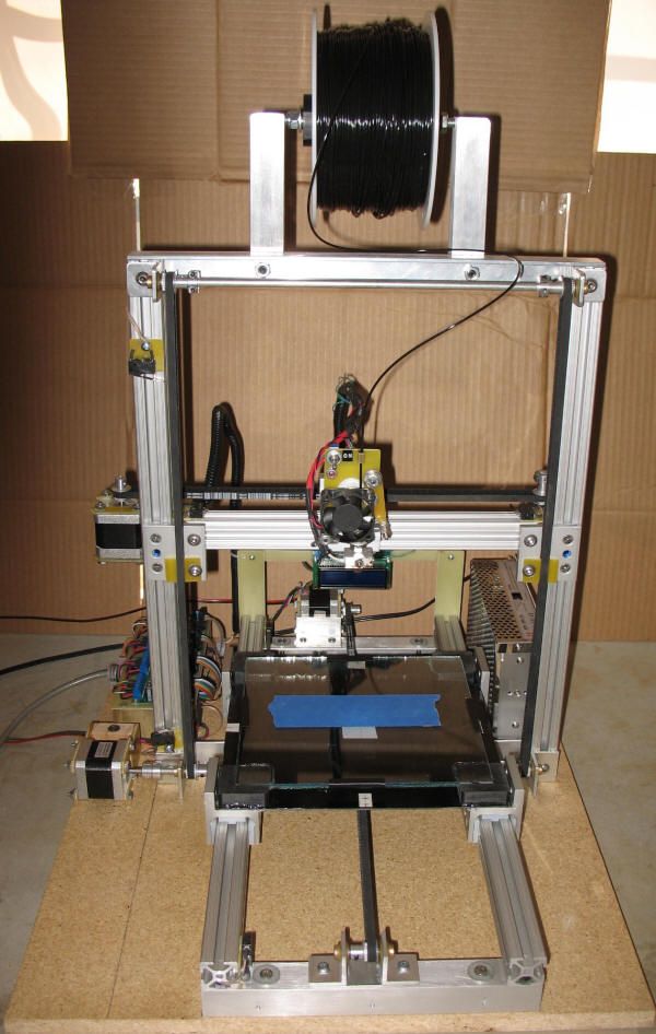
2. Kinematic design of Felix printers.
There are many such printers, such ones are made by MZTO (mz3d.ru), already mentioned by Felix. In fact, the kinematics are the same as those of the Prusa. axes independent of each other. Only now the table does not travel along one axis, but along two at once. Along the Z axis, and along the Y axis.
The design of the table is something like this.
A platform rides on the Z shafts.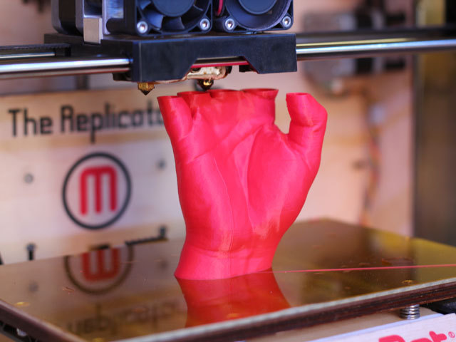 The engine hangs at the back. The table moves along the rails with the help of a belt. The hotend moves only along one axis. The design is very funny, since the table weighs much more than the hotend, and they try to move it along 2 axes at once.
Advantages of this kinematics:
1) There is no second motor along the Z axis. There is no notorious wobble simply because there are 2 shafts and 1 propeller. The screw should also not be fixed from above. If it's not a ball screw.
Ball screw is a separate issue. If we take a high-quality ball screw, say, from the same Hiwin, then it is manufactured according to at least the 7th accuracy class (if rolled, and if polished, then the class is even higher) and must be installed in bearing supports. On the drive side there are 2 back-to-back angular contact bearings, and on the other end a radial bearing with a loose fit to compensate for thermal expansion.
The purpose of mounting a ball screw is to ensure movement accuracy.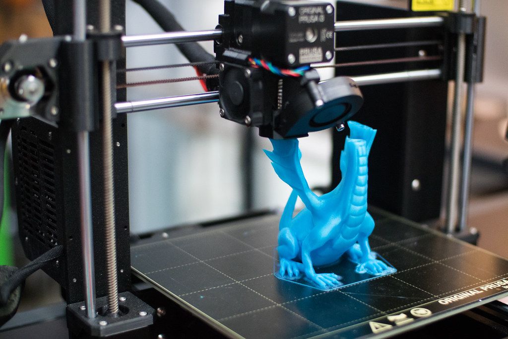 If it is installed incorrectly, money is wasted, and the accuracy will not be higher than a screw-nut pair with a trapezoidal thread. For FDM, trapezoidal accuracy is more than enough.
2) Plenty of space for a direct extruder. As in the previous kinematics, there is room for creativity, to select the one and only extruder that you like.
3) Rigid frame. It is possible to make a normal frame. Rigid, durable. Yes, even cast iron. The guys from Felix decided not to bother their heads and sculpt from an aluminum profile. MZTO went further, bent the steel sheet. And the shelf for the installation of the table was milled from a sheet of aluminum.
4) If we take the design of Felix on the profile, then by replacing a pair of pieces of the profile and the Z screw, you can increase the print area.
Just be sure to add stiffness. And it will turn out like a miracle of design thought. Big, meaningless and merciless.
Kinematic disadvantages:
1) Undoubtedly large twitching masses. The table back and forth, and if you turn on the movement along Z during idle movements (Z-hope), then there will be a disco.
2) There is no way to make him a normal heat chamber. The table moves back and forth and the temperature gradient simply blows away. Hence the problems when printing with nylons or ABS. Small drafts in the room will easily show you where the crayfish hibernate, how the material shrinks.
The table calibration of this printer is similar to the Prusa table calibration, only slightly simpler. It is easier due to the fact that you do not need to level the X-axis, it is automatically set when assembling the frame. We bring the nozzle to the table and twist the lambs.
3. Ultimaker kinematics.
One of the most common variations of Cartesian kinematics.
There are not very many such printers, but they do exist. Variation from Zortrax deserves attention. A variant of the same Raise is closer to the classics.
Zortrax has twin shafts, the reason is simple - they have a direct extruder with a full size Nema 17 motor. Raise Dual has a double direct extruder, so the classic 6 mm shafts are replaced by 8 mm. And the total weight of the 'head' is almost 900 grams.
Kinematics built entirely on shafts. They act both as guides and as pulleys. Kinematics also refers to Cartesian kinematics with independent movement along each axis by its own motor. Very picky about the straightness of the shafts. If you use curved shafts, you can get very funny artifacts on the walls of models. And they will be on all 3 coordinates. Most often it looks like a different thickness of the first layer and small waves along the walls. Therefore, all the salt and the high price of the original Ultimaker is only in high-quality components. Namely, in straight shafts. The belts are often used as ring belts, which simplifies their tensioning system, since it is important that all 4 belts are equally tensioned.
Advantages of this kinematics:
1) The table only moves along one axis. vertical. And the temperature gradient in no way suffers from this. The table is cantilever, so it is desirable to provide stiffeners or take this into account with the thickness of the table.
The metal fold on the table acts as a stiffener.
Many Chinese clones are equipped with such stiffening ribs for the table.
2) Despite the seeming complexity of the kinematic scheme, it is simple and each axis moves with its own motor.
3) The body is closed, which protects against drafts, and therefore delamination. Some put an acrylic door to heighten the effect.
Disadvantages of kinematics:
1) For good printing, it is not enough to buy a pack of even rollers. Collecting all these shafts correctly together is another task. At the same time and buy good bearings.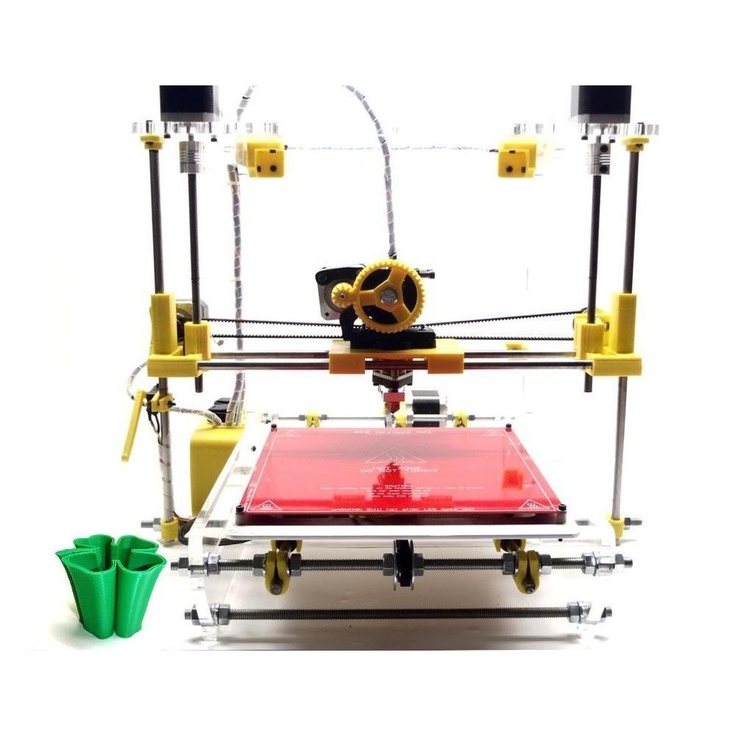 Not that, Chinese junk, which is often sold on Ali, but normal bearings. If the bearings that are placed in the housing rotate poorly, the print will be jerky and with a shift in the layers. The consequences can be asked from Vanya (Plastmaska). Also, when buying leopard bushings, brass bearings with graphite inserts, be prepared for the fact that they will play. And if there is a backlash, the whole structure will knock.
And also, the Chinese like to push brass instead of bronze. And with even wear of brass and graphite, there will be an oily sticky black film on the shafts, which will make the movements harder. Ilya (tiger) offers good bushings. He also wrote about these difficulties.
2) All shaft parallels must be set correctly. I suggest using this device.
4 shafts that go along the walls of the body automatically stand up correctly, but it is important to set the crosspiece correctly in order to get angles 90 degrees in the XY plane.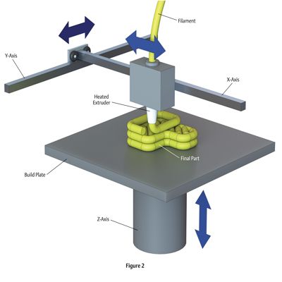
3) The design does not provide for an increase in the printable area with a couple of profile pieces, so the size of the hotend matters. Direct is difficult to put, but you can if you want.
Calibrating the table couldn't be easier. The table is often on 3 attachment points. Move the hot end by 3 points and turn the thumbs.
4. Kinematics used by Makerbot.
Also very widespread. In particular, printers from Makerbot, BQ, BCN3D, Magnum, magnum clone Zenit and quite tolerable makerbot replicas Flashforge and Hori work on this kinematic scheme.
In this case we have independent movement of each of the axes, with a Z table and all the resulting sides.
The main drawback is that the engine hangs on one side of the rolling beam, creating a kind of imbalance. This shortcoming was compensated in a two-extruder version - BCN3D Sigma. There, each bowden head has its own engine to move along the beam. And they are installed at the edges of the beam and balance each other.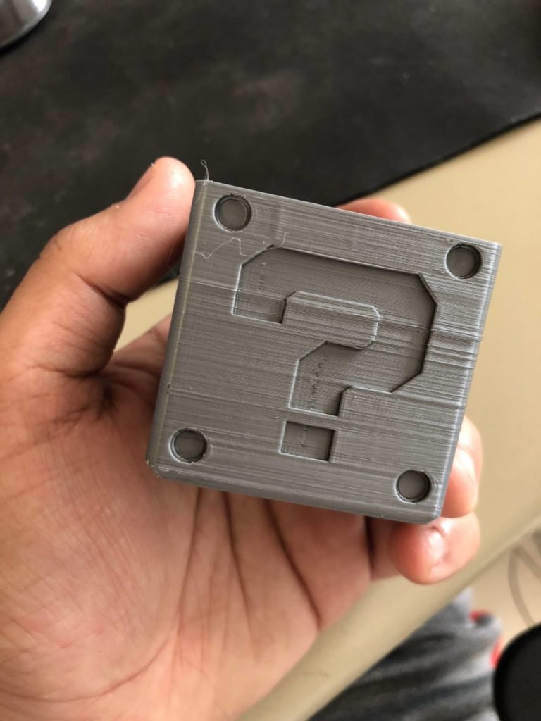 For uniform movement of each of the edges of the beam, 2 shafts, pulleys and belts are used. Belts must be tensioned equally.
Advantages of kinematics:
1) Independent movement of each axis.
2) Z-moving table. The temperature gradient does not suffer from 'blowing'.
3) Enclosed body. If not closed, then there is a quite normal chance from the point of view of aesthetics to close it.
4) Scalable kinematics possible. Various BigREPs and others with 1m print areas use exactly this kinematics, as various H-bot/CoreXYs will ring like hell due to the presence of 4-5m belts and their stretching during accelerations.
Disadvantages of kinematics:
1) Unbalanced masses on the moving beam, hence the maximum print speed, with acceptable quality no more than 60-80 mm/s. Some manage to balance them and it is not so noticeable.
2) Bulky structures on the shafts to avoid unbalance during movements.
3) Make sure that the belt tensions on the right and left are the same.
4. H-bot/CoreXY kinematics.
Next in distribution. Also Cartesian. Two motors are stationary, but move the carriage along the rails with one long piece of belt, or with two, but shorter. The math is more complicated than the previous ones, as it is necessary to synchronize the rotation of both motor rotors. That is, to move along each axis, you need to rotate both motors, and to move diagonally, only 1.
[IMG]http://www.doublejumpelectric.com/projects/core_xy/pics/hbot.svg[/IMG]
In fact, the mathematics for rotating motors is the same, but the implementation in mechanics is different. One of the biggest disadvantages of the H-bot over the CoreXY is that the belt tends to rotate the beam as it moves.
In the picture on the left, this is noticeable, the forces on the right and the forces on the left create a torque. Therefore, to implement this kinematics, the rigidity of the kinematic scheme is necessary. Most often it is implemented in rails.
With rigid beam. Some do, of course, on the shafts, but in the end - this is not a fountain.
And then they realize this and move to the rails.
For they are both easier to assemble and set up, and it is not necessary to invent carriages so that the shafts do not need to be fixed well.
CoreXY, unlike the H-bot, is driven by two belts.
And so, for ease of understanding, I will describe the positive and negative aspects of each variation of this kinematics.
H-bot.
Advantages:
1) Only one belt is needed, and the scheme provides for its operation without twisting.
2) It is more convenient to tension one belt than 2, so only one normal tensioner is needed in this scheme.
Even so.
Disadvantages:
1) The belt tends to stretch over time, and since the amount of stretching directly depends on the length, it is necessary to monitor its tension. Otherwise, you will get ugly waves on the surface before the stops.
With a loose belt tension, the carriage will have this play.
2) It is necessary to set the rollers strictly perpendicular to the XY plane, since if the roller is slightly skewed, the belt will be eaten against the roller shoulders. And we will get such a bullshit.
Tested in the skin and ZAV printer. Therefore, I always recommend that the rollers be fixed normally, and not cantilevered, in order to avoid bending the roller axis from belt tension.
3) Complicated mathematics, due to which at speeds above 100 mm/s there may be problems with the lack of resources of 8 bit boards.
CoreXY.
Pros:
1) Two short pieces of strap. They are easier to find than one long one.
2) The forces balance the beam, but do not tend to turn it, so these kinematics can also be assembled on shafts.
Disadvantages:
1) There are schemes with belt twisting and belt transition from one level to another - this is not very pleasant for a belt. Especially when one belt rubs against another. This moment is on video.
:{}
2) The difficulty of tightening the belts. They must be tensioned equally, otherwise the tension forces will tend to turn the carriage.
3) Complexity of assembly and development. It is necessary to maintain the verticality of the rollers, relative to the horizontality of the platform for installing motors and rails. A slight misalignment of the rollers will cause the belt to tend to slide down the roller, and if it rests against the shoulder of the roller, it will creak, if the shoulder is large, and if it is small, it will try to drive into it, as in the photo from the h-bot description .
The general disadvantage of kinematics is poor scalability. That is, it is very problematic to set such a kinematics for a print area larger than 300 * 300 simply because of the elongation of the belt during printing. For small printers with high print speeds - one of the best kinematics.
5. Delta kinematics.
The kinematics are based on the movements of the delta robot.
Only the hotend is installed instead of grippers. It has its own set-up problems, but it can take a very long time to print. It is rare when direct extruders are installed, since the effector (a platform for installing a hot end) is often mounted on magnets and it is necessary to unload it as much as possible. But in order to reduce the length of the tube (more specifically, the effect of the length of the tube on the print quality due to the correct adjustment of the retracts (pulling the plastic rod back to reduce its leakage from the expansion)) on the print quality, the extruder is hung on the same carriages, but on separate hangers. This reduces the length of the bowden tube and increases print quality.
Advantages:
1) Easy to customize. To increase the height, it is enough to buy 3 pieces of a longer profile, and increase the maximum height in the settings.
2) Takes up little space. It is more often high than bulky in length and width, due to this compactness.
3) If you make a light effector (carriage on which the hot end is installed), then you can achieve high speeds without losing print quality.
4) Vertical movement is the same as XY movement. Thus, there is no sticking of linear bearings on the table crossings, as in Cartesian printers, no extra motors rolling on the beam...
5) The absence of protrusions makes it possible to close the housing and stiffen the frame.
6) The aesthetic part - it's more interesting to stick to the work of the delta.
Disadvantages:
1) Difficult mathematics of movements, it is recommended to install 32-bit boards at once.
2) Complicated setting. A common problem in tuning is to remove the so-called 'lens', because each rod rotates with a radius, and if the tuning is incorrect, your printed plane will be either a convex or concave lens.
3) It is difficult and expensive to make a rigid frame, so that it would not dangle from the constant jerking of the carriages.
4) Difficulty installing a direct extruder. It turns out to be heavy, and since many deltas are made on magnets, it will not be possible to accelerate. Although, there is one neat and easy solution - installing a ready-made direct extruder with a gearbox. Like E3D Titan Aero or Bondtech BMG.
5) Parts precision problems - any unevenness and misalignment will be visible even if they are on the same axis. And they add up along the axes.
To summarize , do you want a small printer (no larger than 300*300 mm) with nimble kinematics? Then you should go to Ultimaker or H-bot/CoreXY.