Mesh 3d print
Mesh best STL files for 3D printing・Cults
Fidget Flex
Free
women join mesh
€1.15
cribriform ring
€5
Pin mesh diamond lips fashion ring Us sizes 7 8 3D print model
€3.84
GOAL MESH CLIP
Free
sculture woman woman love heart lesbian
€11 -75% €2.75
sculture man man love heart
€11 -75% €2.75
SpikeyMesh - 3D printing with embedded fabric mesh
Free
Cute Cat
€27. 86
FlexMesh 2.0 compatible shapes
Free
Noctua NFA15 fan cover
Free
Gutter guard clips
€2.90
Bestway Pool skimmer on cup-holder
Free
Giraffe Wire Frame Art - Resin Printing
Free
Fox Wire Art - Resin print
€7.16
sculture woman and man love broken heart
€11 -70% €3.30
Puppy - Little dog - resin print
Free
Wolf - Resin print - Wire art
€5.87
Fiat Bravo 2 (198) Honeycomb grille
€20.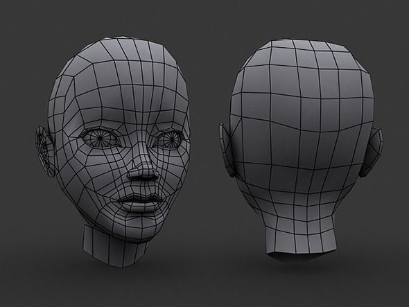 49
49
Stylized Female Base Mesh
€4.79
The Ultimate 3 Steps Leveling - level once like this and never again
Free
Base Female Head
€0.59
Heart Mesh Pendant
Free
Heart Mesh
Free
Turtle Mesh Pendant
Free
Heart Celtic Pendant
Free
Bracelet Mesh
Free
Ball thing
Free
Alien bracelet
Free
zombie mesh base
€2.50
realistic hulk mesh base
€2. 50
50
Swimwear cookie cutter cutting
€1.24
Owl on tree in voronoi like style
€6.79
Elephant - mesh wire art
€5.50
Gorilla - Mesh Wire
€8.79
texture, fabric, knitting, knitting, chainmail, texture cloth knitting
€2.04
Snake skin ring
€1.76
Fan mesh 140mmx140mmx3mm
Free
Customizable sieve / filter / strainer
Free
Virgo zodiac sign
€4.49
Aries zodiac sign - resin print
€7.98
Pisces zodiac sign - resin print
€11. 99
99
Aquarius zodiac sign - resin print
€9.60
( Airsoft ) Side attachment for helmet
€2
Mesh Test
Free
Bracket 4 Fins Orthodontics
€1
3d pave ring
€7
Applemesh
Free
MeshLab
MeshLab the open source system for processing and editing 3D triangular meshes.
It provides a set of tools for editing, cleaning, healing, inspecting, rendering, texturing and converting meshes. It offers features for processing raw data produced by 3D digitization tools/devices and for preparing models for 3D printing.
Previous Next
NewsNew MeshLab and PyMeshLab version: 2022.
 02
0228/02/2022
We released MeshLab and PyMeshLab 2022.02, with new features, bugfixes and improvements! You can check for more details here and here.
MeshLab and PyMeshLab 2021.10 released
29/10/2021
MeshLab and PyMeshLab 2021.10 have been released, with lot of bugfixes and new features! You can check for more details here and here.
MeshLab 2021.07 has been released
23/07/2021
MeshLab 2021.07 is out! In this version we introduce support to several file formats (*.gltf, *.glb, *.nxs, *.nxz, *.e57) and a brand new plugin for exact mesh booleans. You can download in the download section, or in the github release page.
You can check all the details regarding the new release here.
MeshLab 2021.05 released
27/05/2021
MeshLab 2021. 05 has been released! You can download in the download section, or in the github release page.
You can check all the details regarding the new release here.
New version 2020.12 is out!!
01/12/2020
MeshLab 2020.12 has been released. With this version, we dismiss meshlabserver in favour of PyMeshLab, our new Python library for mesh batch processing using MeshLab filters.
We release also a new version that stores data with double precision. For further details, you can read the discussion in our GitHub page.
Changelog:
- lot of bug fixes
- GUI improvements
- new version 2020.12d that stores data with double precision (beta!!)
MeshLab 2020.07 released
06/07/2020
MeshLab 2020.07 is out! You can download in the download section, or in the github release page.
Changelog:
- new plugin "Global Registration" based on OpenGR library;
- option to reverse wheel direction;
- snap package allows to associate file extensions and to open files on external disks;
- u3d exporter is now more stable and works on every platform;
- removed support for XML plugins and QtScript dependecy;
- VisualSFM (and some other formats) output *.nvm, *.rd.out projects supported by meshlabserver
- various bugfixes
MeshLab 2020.06 released
01/06/2020
MeshLab 2020.06 is out! You can download in the download section, or in the github release page.
Changelog:
Due to the deprecation of QtScript and all the issues related to it, we are dropping from MeshLab the support to XML plugins, and therefore all the XML plugins have been transformed to classic plugins in this MeshLab version. The involved plugins are:
- Screened Poisson;
- Measure;
- Voronoi;
- Mutualinfo;
- Sketchfab;
Due to this porting, all old .mlx MeshLab scripts that involve one of these plugins may not work on MeshLab and MeshLabServer 2020.06. Starting from MeshLab 2020.07, XML plugins won't compile anymore and they cannot be loaded anymore.
New MeshLab 2020.03 and automatic deployment
26/3/2020
We are happy to annouce that MeshLab 2020.03 is out! We set up an automatic system on our Github repository to automatically release a MeshLab version every first day of the month. Ultimate release can be found in the release page.
Note for Windows version: before installing MeshLab 2020.03, please uninstall manually any old MeshLab version. This is a known bug of the installer and will be fixed as soon as possible in future versions.
SGP Software Award
6/6/2017
We are proud to announce that on July the 6th, at the Eurographics Symposium on Geometry Processing (SGP), MeshLab has been endowed with the prestigious Eurographics Software Award!
The award has been given for "having contributed to the scientific progress in Geometry Processing by making the software available to the public such that others can reproduce the results and further build on them in their own research work".
MeshLab 2016 Released
23/12/2016
After a very long time, a huge rewriting process, and a strongly renewed effort the new MeshLab version is finally out!
- Total rewriting of the internal rendering system. Huge rendering speed ahead!
- Screened Poisson Surface Reconstruction updated to the very latest version.

- New Transformation filters.
- New ways of getting metric information out of your models.
- Transformation matrices are now used more uniformly among filters.
- Alpha value is now used properly by all color-related filters.
- Improvement and typos removal on various help/description texts.
- Direct upload of models on SketchFab
- Raster registration on 3D model based also on 2D/3D correspondences
- Bug-fixing on almost all filters.
MeshLab 2022.02
28/02/2022Win 64 MacOS Linux AppImage Linux FlatPak Sources Other Releases Sample Meshes
FeaturesSupportMister P.
 YouTube tutorials
 Basics
This playlist shows the basic concepts for the 3D model handling in MeshLab.
Features
This playlist describes interesting features of MeshLab: edit, filters, decorations, that can be useful in your everyday "mesh processing" life.
3D Scanning pipeline
This playlist describes the main steps of the scanning pipeline performed with MeshLab.
Cleaning
This playlist describes way to "clean" your mesh by removing unwanted geometry or attributes.
Questions and Forum
For question, clarifications and any kind of doubts about MeshLab and how to get the best result with the various filters, use stackoverflow.
Be specific, and tag your questions with MeshLab.
Search Question Ask a Question
Bug Report
Please report on github ONLY bugs and malfunctioning. Please do not file as github issues questions about how to use MeshLab.
Before issueing a bug, please, read carefully how to report a bug Report a Bug
Bragging
For sharing nice pictures, reporting interesting experiences, thanking (or blaming) the developers, or just bragging on your last results, follow the official facebook MeshLab page.
Remember: do not ask technical questions on facebook. (facebook is neither easily searchable nor well indexed: any effort done in answering technical questions is a bit wasted)
MeshLab
on
Licensing
MeshLab sources are distributed under the GPL 3.0 Licensing Scheme.
The 'MeshLab' name is a EUIPO trademark owned by CNR.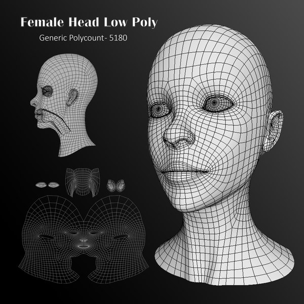
MeshLab Logos ( ) are distributed under
Creative Commons Attribution-Sharealike 4.0 International License and they can be freely used inside any wikimedia project.
The simplest way to show your appreciation of the MeshLab system is to remember citing it whenever you have used some of its functionalities.
There are many publications related with MeshLab, in case of doubt use the first one, but, please, look through the list and cite also all the proper ones.
As general info, MeshLab is an open-source system whose development has been led by the Visual Computing Lab of ISTI-CNR since 2005. It has been downloaded more than 3 million times, and, according to updating stats, it is currently used by more than 100,000 users.
{{pi. description}} description}} | {{pi.paperAuthors}} {{pi.paperTitle}} {{pi.paperVenue}}, {{pi.paperYear}} |
|
What is a fill pattern in 3D printing?
3DPrintStory 3D printing process What is a fill pattern in 3D printing?
Quite often, 3D printing is used to produce parts that can be easily produced using another manufacturing technology. However, while the end results may look the same on the outside, what's on the inside can be drastically different.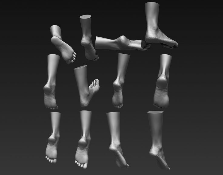
The main advantage (and necessity) of 3D printing is that parts can have different degrees of filling with material. From a production standpoint, this reduces the amount of material needed and the cost as well as the weight of the final product. And in terms of 3D printing, it saves precious time!
What's inside the outer shell of a 3D printed model is called infill. It can be adjusted by the ratio of density (0% - emptiness, 100% - solid) and pattern.
Next, we'll take a look at the various fill patterns, in particular those available in Cura.
What filling options are available?
In the latest version of Cura (4.5), 13 infill types are available. They are grouped below according to what they are best suited for:
- Models and figurines (low strength): Lines, zig-zag ;
- "Standard" 3D models (medium strength): Grid , triangles , tri-hexagon ;
- Functional 3D models (high strength): Cubic , cubic subdivision , octet , quarter cubic , gyroid ;
- Flexible 3D models: Concentric , cross , cross 3D .
Models and figurines
Recommended infill density: 0-15%
3D models that are used as models or figurines usually do not require special strength, as they are not subjected to heavy operating conditions and are not subjected to heavy loads .
For these 3D printing options, lines or zig-zag fills are best because they provide the fastest 3D printing.
Similar to the "rectilinear" in other slicers, both templates create a 2D grid where 3D prints only along one axis on one layer. The difference between the two is that lines create multiple lines per layer, while a zigzag is just one continuous line (unless interrupted by a pattern).
Models or figurines work well with simple filling patterns. Prototypes of your future parts are also good candidates, given that they do not need to be tested for durability.
"Standard" 3D models
Recommended infill density: 15-50%
For 3D models subjected to low stresses, such as the media guide above, use a medium strength infill pattern.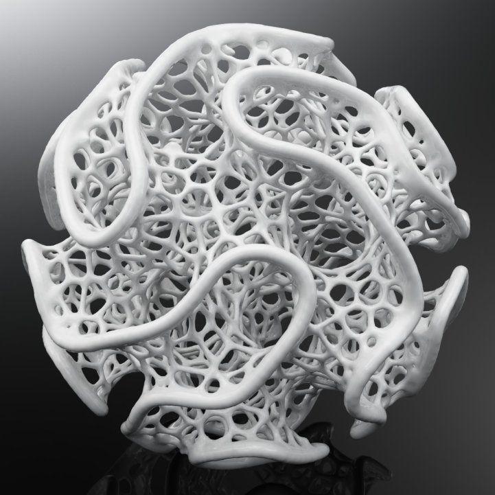 The most appropriate fill options are grid, triangles, or tri-hexagon. However, please note that these patterns can increase print times by up to 25% compared to lines.
- grid: A clear 2D template. The main advantage is the speed of 3D printing, as it is the least complex of the three;
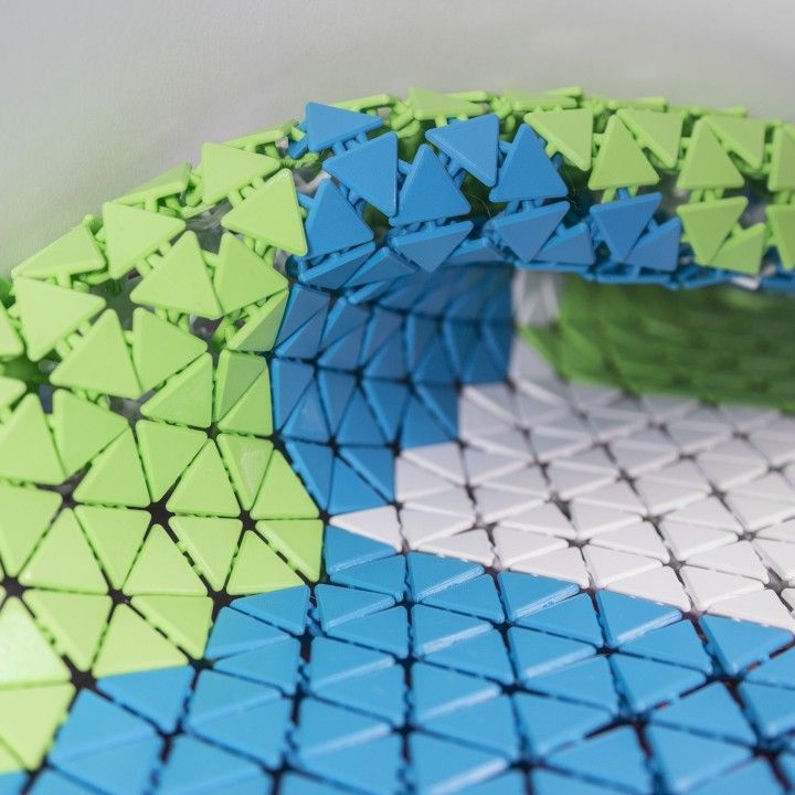
- triangles: A 2D mesh made up of triangles. This pattern infill option has an inherent strength advantage when a load is applied perpendicular to the object's surface. It makes sense to use for parts with thin rectangular components that might otherwise have very few connections between the walls;
- tri-hexagon: This 2D fill option creates hexagons interspersed with triangles. One of the advantages is that hexagons are a very rigid geometric figure, which ensures high strength of the finished product. In addition to this, the tri-hexagon filling gives shorter lines to connect each side, resulting in fewer bending issues due to poor cooling during 3D printing.
Functional 3D prints
Recommended infill density: > 50%
Functional 3D prints such as a shelf bracket require high strength in many directions.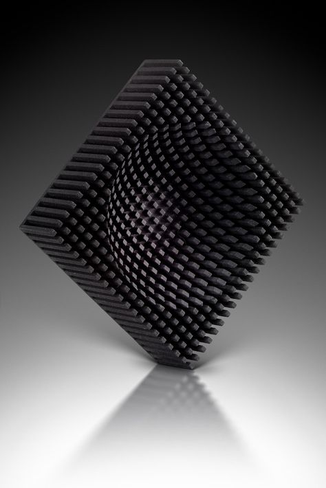 Excellent candidates for fill patterns include: cubic, cubic subdivision, octet, quarter cubic, gyroid.
- cubic: this is a three-dimensional pattern of stacked and tilted cubes;
- cubic subdivision: this is a variant of the cubic type that uses less material;
- octet: This pattern variant, also known as tetrahedral infill, combines pyramid shapes;
- quarter cubic: this three-dimensional pattern is similar to the octet, but half of the pyramidal shapes are offset from the other half;
- gyroid: A unique 3D pattern that gives the impression of waves. However, it handles loads equally well in many directions. Thus, this infill pattern will be a good choice for a part that will be subjected to various loads.
The above 3D model infill options are often used even at lower infill densities due to their aesthetic appeal. Some people just like the effect of the internal pattern, which can be observed directly during 3D printing.
Flexible 3D models
Recommended infill density: 0-100% (depending on how “soft” you want the final product to be).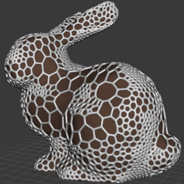
For flexible materials such as soft PLA MatterHacker, flexible infill patterns must be used to maintain the flexible nature of the print. Fill patterns such as concentric, cross, cross 3D are best for these types of 3D models.
- concentric: This 2D pattern creates "waves" within the print, mimicking the shapes of exterior walls. This is very similar to how a stone thrown into water leaves concentric circular waves on the surface;
- cross: Another 2D pattern that creates a grid of very fancy crosses. The gaps between the crosses and gratings allow bending and twisting;
- cross 3D: This 3D pattern is similar to a cross, but as the 3D model grows, the lines move at an angle. The end result is an object with a bit more rigidity.
Tips and Tricks
The choice of fill pattern for a 3D model is important, but that's not all. Here are a few things to keep in mind the next time you're configuring Cura's 3D print settings.
Fill Line Direction
One of the often overlooked fill settings is the fill line direction.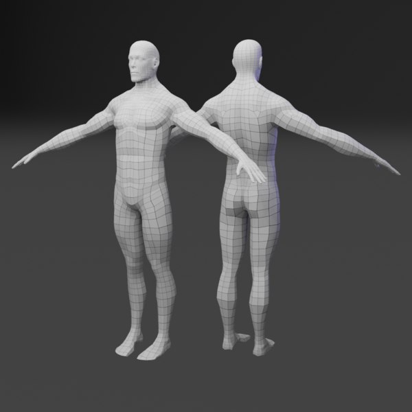 The default is 45° so that both X and Y motors work together to print infill at maximum speed. However, it may be more useful to orient the infill at a different angle to maximize the strength or flexibility of the part, especially if its walls are aligned diagonally.
Gradient Fill vs. Gradual Fill
When it comes to fill, we usually think of it as uniform throughout the inside of the part. However, this should not be the case.
Using gradient infill, you can set up 3D printing with a higher infill density around the perimeter. Generally speaking, this should maintain the effective strength and stiffness of the part while using less material. This option is not built into Cura, but it can be implemented relatively easily with a Python script.
Gradient fill should not be confused with gradual fill, which provides something similar, but along the Z axis rather than the X and Y axes. In other words, this option makes the fill denser at the top of the 3D model compared to the bottom.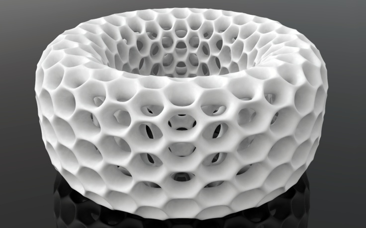 It can save material and time while maintaining sufficient strength.
Multiple filling density settings
Since the release of the fourth version of Cura, it has been possible to set the settings for each model. This allows for some neat design tricks, including multiple infill types and densities in a single model.
With the ability to set custom settings for each imported model and Cura's ability to easily combine them together, specialized support can be provided in specific areas.
While this will certainly require a lot of manual work and tweaking, this feature may become easier to use in the near future.
Requirements for 3D models for 3D printing and CNC processing
01/16/2017 in 3D modeling, Instructions
Contents:
- Introduction
- Product creation process.
- Requirements for models for 3D printing and CNC processing.
- Fixing non-critical bugs with NetFabb.
- Fixing non-critical bugs with MeshMixer.
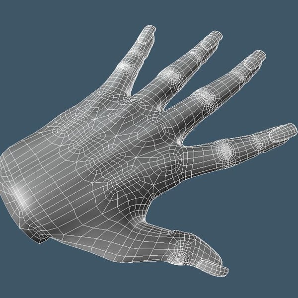
- Fixing non-critical bugs with Materialize Magic.
- Examples of the most common errors.
Introduction.
In this article, we will talk about the main and general parameters that a model must meet in order to obtain high-quality 3D printed products. Let's discuss common errors that occur in the process of creating three-dimensional models in terms of a high-quality polygonal mesh and how to quickly fix them. Requirements for 3D models and quality issues in terms of the accuracy of manufactured parts are described in another article: The actual size of the product after 3D printing.
The process of creating a product.
Structure of the additive manufacturing process for the production of products:
| Designer / 3Dartist | 3D Printing Service | Bugs discussed |
| 1. Creating a 3D model of | ||
2. Export/convert 3D model to required format Export/convert 3D model to required format | 3. Checking the model for suitability | 4. Pass/fail to minimum allowable thicknesses. |
| 6. Preparation of control program for 3D printer (GCode) | 5. Compliance / non-compliance with the requirements for the polygonal mesh of the 3D model. | |
| 7. 3D printing process. | ||
| 9. Quality control. | 8. Post-processing process. |
In accordance with the presented algorithm, at the first stage of product creation, a 3D model is developed using modeling programs in accordance with the terms of reference and standards requirements. After that, it is necessary to export the data of the simulation result program file to a format accepted by the program of the additive manufacturing control machine (for example, “STL”). The modeling process can now be done not only in solid format, but also immediately in STL. Before the next stage, possible defects in the model are identified. A model intended for 3D printing must be hermetic, monolithic and not contain cavities and gaps in the walls, which is ensured using special programs. Next, the information from the STL file is converted into commands, following which the 3D printer produces a product, this is the so-called GCode.
During this procedure, you should select the desired scale of the part, the correct position in space, and accurately position the model on the work surface. The result of the whole process, strength, surface roughness of the part and material consumption depend on this . After the settings are made, the model is divided into layers of material, which are “fitted” into the body of the part in one working cycle of the additive machine. This process is called slicing. Slicing is done using the software supplied with the machine, or using special tools (Simplify, Skein-forge, Slic3r, KISSlicer, MakerWare, etc. ). The G-code obtained in the previous step is transferred to the 3D printer via flash memory or via a USB cable. In the process of preparing and setting up the additive machine, calibration, preheating of the working bodies, selection of the model material and setting the parameters of the equipment operation modes that depend on it are performed. On professional level devices, this step can be combined with the slicing process procedures. After all the preparatory operations are completed, the printing process starts, that is, the layer-by-layer combination of materials. Its duration depends on the type of technology and the selected parameters for the accuracy and quality of the part.
Requirements for models for 3D printing and CNC processing.
- List of file formats by 3D technologies.
- FDM (ABS, PLA, FLEX, HIPS, etc.): .STL .OBJ
- SLS (polyamide): .STL .OBJ
- SLA, DLP (photopolymer): .
STL .OBJ
- SLM (metal): .STL+STP(STEP) .OBJ+STP(STEP)
- Multicolour plaster: .OBJ+texture .WRL+texture
- Polygon mesh.
- The mesh must be uniform and closed. A model consisting of several polygonal meshes is not allowed! Intersection of polygonal meshes is not allowed! Holes in the grid are not allowed!
- Multiple models in one file are not allowed. Each object needs to be saved as a separate file.
- The number of polygons must not exceed 500,000.
- The wall thickness must be at least the specified values for each technology.
- Inverted normals are not allowed! The outer normal should face outward. This problem is especially common when mirroring the model in some 3D modeling programs.
- The dimensions of the model must correspond to the dimensions of the real object.
In 95% of cases, errors in files are not critical and can be easily corrected using specialized programs that can be easily found on the Internet.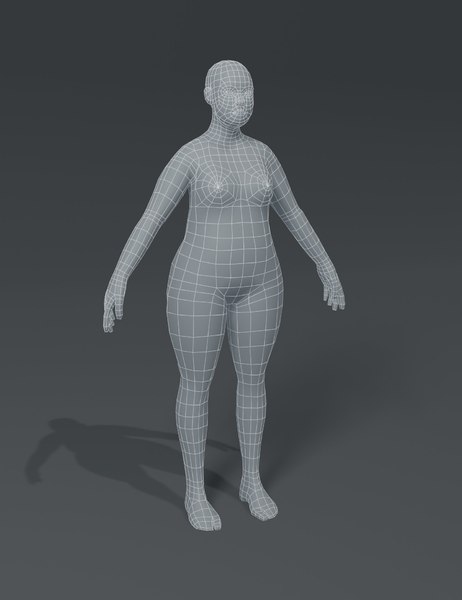 Even if you are sure that everything is in order with the model, it does not hurt to check it once again for correctness.
NETFABB - as a solution to most file errors.
MESHMIXER is a powerful and convenient alternative.
- Wall thickness analysis of the model.
It should be understood that there are several 3D printing technologies. They differ not only in the materials used, but also in the accuracy of the equipment. Different equipment has its own resolution. Therefore, before sending the file for printing, it is necessary to make sure the quality of the model in terms of the specified thicknesses in the walls, rods, mesh ceilings. Detailed article about checking models for thickness.
Fixing non-critical bugs with NetFabb.
NETFABB (download for PC or download for Mac) is a program that allows you to solve almost any issue related to 3D printing. Let's go through the main functions of this software, which AutoDesk itself bought at one time.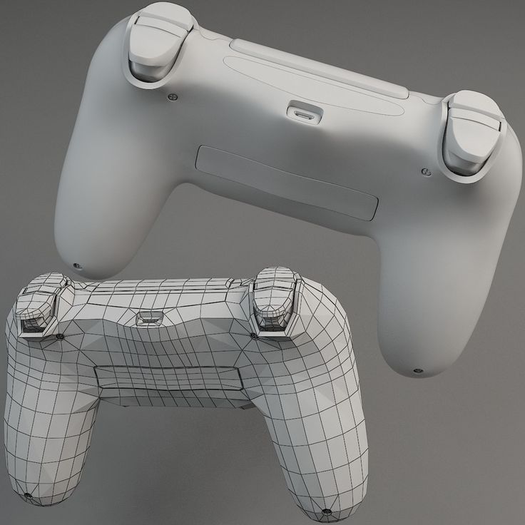
The program shows the outer part of the polygon in green, its inner normal in red. Ideally, the model should be all green. If you observe red spots, then these are polygons that are turned outward. If the entire model is highlighted in red, then the entire mesh is turned inside out.
Even if the model is green, but there are errors in your file, the program will display a big exclamation mark in the lower right corner of the screen, and will also not be able to calculate the volume of your model.
To treat the model, click on the red cross on the toolbar at the top of the screen. The program will put you into the treatment mode, and will indicate in yellow the breaks in the polygonal mesh, if any.
This program has functions for removing or adding polygons, changing sizes or proportions. (I will leave these functions for independent study). I recommend that you study the entire toolbar in order to easily understand how, where and which polygons we can select and what we can change.
To invert normals, select the polygons that look “in the wrong direction” and click on the “invert normals” button. Then click on the “Apply Repair” button.
If your model was initially all green or inverting the normals didn't remove the exclamation point, and the volume has not yet been calculated, you need to apply automatic treatment. To do this, go back to the treatment mode by clicking on the red plus. In the treatment mode, select "Automatic treatment", then select "Default Repair" and click "Extrude".
The program has now done its best to repair the model automatically. Click "Apply Repair".
Typically, these steps should have fixed your model. If after the performed operations an exclamation mark is on and there is still no volume, then you are among those 5% when the model has critical errors and errors are laid down at the modeling stage.
Fixing non-critical bugs with MeshMixer.
Autodesk MeshMixer is a free software for working with 3D mesh models. You can download the program from the link. The program does not have tools for creating 3D models, but a wide range of tools for modifying them and preparing them for 3D printing. The main difference between this software and NETFABB is that MESHMIXER officially supports the latest versions of macOS. For me, this is a decisive factor, because I always carry a MacBook with me, and a Windows computer is only in the office. In turn, NetFabb stopped supporting software for macOS.
As with Netfabb, you need to drop the STL model into the MeshMixer window.
At first glance, the model looks good, but let's try to test it for 3D printing suitability (mesh requirements). To do this, you need to analyze the model for errors. To do this, go to the “Analisis” section, then click on the “Inspector” button.
On the screen, we can see how the program highlighted areas on the model with bright colors that do not meet the requirements, which means they have errors.
In order to fix (cure) these errors, click on the “Auto Repair All” button. The program will try to remove errors automatically. Checking before 3D printing is a must. Even if outwardly the model seems suitable to you, it is still worth checking. In the picture below, you can see the errors that are inside the mesh, although everything looks good with the model.
However, this treatment does not always help. For example, if the model has a huge number of errors that the program is not able to remove automatically, then you will have to correct the model yourself in the program where the model was originally created. In case of a large number of errors, the program will indicate their presence even after you have tried to do automatic treatment. The picture below is an example of a very large number of shortcomings and errors that the program is not able to remove by itself.
This usually happens when the model is being prepared for rendering rather than 3D printing. That is, there is a huge number of surfaces, but they are not connected into a single grid.
Fixing non-critical errors with Materialize Magic
The 3D model healing feature in Materialize Magic is located in the Fix tab.
After that, select the “Correction Wizard” command. Next, you need to alternate the “Update” and “Autocorrect” buttons.
Do this several times. Sometimes for a long time. Until the moment when the number of errors becomes minimal or disappears altogether.
After the upgrade, the result shown below can be considered successful. All checkboxes must be green.
Complete the treatment by following the recommendations and save the corrected model!
A very important point! Treatment in automatic mode occurs according to the principle of adding or removing polygons. Therefore, after automatic treatment, fully check the model for the correct form.
Learn more


