Diy raspberry pi 3d printer kit
How to Build Your Own 3D Printed Raspberry Pi Robot (Updated)
Skip to main contentTom's Hardware is supported by its audience. When you purchase through links on our site, we may earn an affiliate commission. Here’s why you can trust us.
(Image credit: Tom's Hardware)Update 7th August 2022: We've updated this article to include how to program the Explora in Python on page 2.
Original Tutorial Published June 4, 2022:
Building your own robot is one of the most satisfying things you can do. It combines mechanical, electrical, and programming skills together in a way few projects do.
I’ve been building robots for a couple of years now and love to expand my knowledge and skills by using different controller boards, motors, wheels, and sensors to detect the world around the robot.
Raspberry Pi robots are particularly impressive. The Raspberry Pi provides the robot with the full power of Linux and a plethora of Python libraries. With all of this power, it means we can add advanced machine learning, computer vision, and Internet connectivity into the mix. All this at an affordable price point and tiny form factor too.
Building Raspberry Pi robots from kits, such as Pimoroni’s Trilobot, or from a custom design such as Explora, is fun and helps develop skills such as programming in Python, mechanical design, and electronics. People love playing with robots and teaching them to perform tasks and move around the environment unaided.
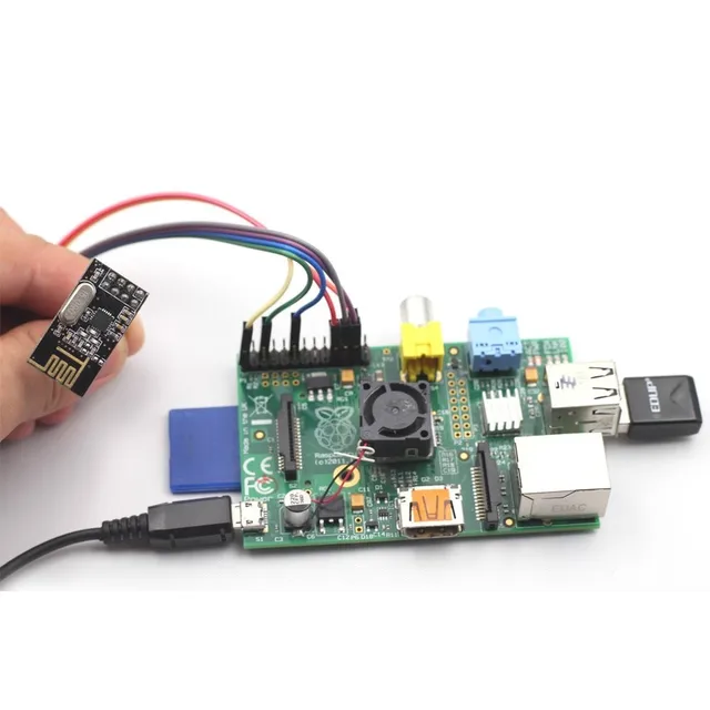
Explora uses the Pimoroni Explorer pHAT (we included the Explorer HAT Pro in our best Raspberry Pi HATs guide) to control the motors and has a handy Python library to make this simple. Explora is programmed in Python and uses sensors to avoid obstacles and follow your handExplora can also be remotely controlled over Wi-Fi.
Explora can detect objects in front of it using an HC-SR04 ultrasonic range finder module. These modules come in either a 5v version or a 3.3v version (HCSR04+ or HC-SR04P). The Explorer pHAT is 5v tolerant, but it's best to get the HC-SR04+ or HC-SR04-P version to be on the safe side. Using the 5v version on a Raspberry Pi can damage the board.
Explora was designed using AutoDesk Fusion 360 . Each piece is a discrete component to enable easier 3D printing. Fusion 360 makes it really easy to export the models into STL files, ready for slicing and then 3D printing. To slice the robot parts (creating the instructions for a 3D printer to print the part) from Fusion 360 I use Cura, and then upload it to OctoPrint to manage the print jobs. The 3D printed parts are designed to be quick and easy to print, and the whole thing is easy to assemble using a couple of screws and wire up.
My personal choice of 3D printer is the Creality Ender 3 Pro and Ender 3 V2.
The electronics for the project are relatively straightforward and involve some soldering. You will need to solder wires to each motor and then to some Male DuPont cables (jumper jerky), one set per motor.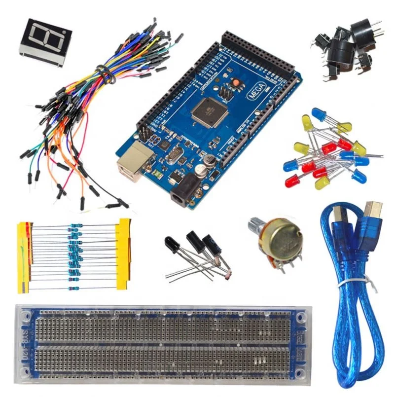 You’ll also need something to hold the motors while you solder the wires to the tiny motor connectors which can be a bit tricky if you’ve not done this before. Some “helpful hands” or modeling clay is useful to keep the wires in place.
What You Will Need
- A 3D printer and filament
- 8 x M3 10mm screws and nuts
- 4 x N20 Motors
- 1 x Pimoroni Explorer Hat
- 1 x Raspberry Pi Zero 2 W / Raspberry Pi Zero W
- USB Powerbank battery pack
- 400mm of red wire - solid core is preferable over the braided wire
- 400mm of black wire - solid core is preferable over the braided wire
- 8 x M2.5 Stand-offs (with male screw)
- 4 x M2.5 Stand-offs (without male screw)
- 8 x M2.5 Screws
- 4 x Moon buggy wheels
- 4 x Male to female Dupont cables (200mm)
- Some velcro straps for the battery pack
- SD Card for the Raspberry Pi Zero
- PIR Obstacle sensor
Tools
- Soldering iron
- Solder and some flux
- Screwdriver
- Wire cutters
- Wire strippers
- Helping hands - for use with soldering
- A computer with an SD card reader slot
3D Printed Files
- 1x Chassis
- 4x Motor holders
- 1x Camera Holder
- 1x Camera back
- 1x Top section
Building Explora
(Image credit: Tom's Hardware)The print times for each of Explora’s parts depends on your specific printer and quality settings. I found the files took the following amount of time to print:
Swipe to scroll horizontally
| # | Part | Approx Time to Print |
|---|---|---|
| 1. | Chassis | 5 hours 16 minutes |
| 2. | Top Section | 2 hours 22 minutes |
| 3. | Motor Holders - all 4 at once | 3 hours 44 minutes |
| 4. | Camera holder & Camera holder back at once | 2 hours 30 minutes |
I prefer to use PLA+ for my prints and usually have some white or yellow filament already in each printer, ready to go.
To Prepare Explora’s 3D Printed Parts
(Image credit: Tom's Hardware)1. Download the 3D printable STL files.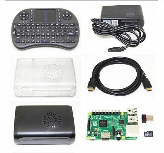
2. Slice the parts using Cura - We like to use Cura, but you are free to use an alternative. and don't forget to enable supports for the motor holders
3. Transfer the G-Code file from Cura to your 3D Printer. Save the G-Code file to an SD card (if that's how your 3D printer accepts files) alternatively you can use software such as OctoPrint that runs on a Raspberry Pi and presents a Web-based interface for managing 3D Print jobs. If you’re using OctoPrint you can drag the G-Code file over the left-hand side of the page and it will begin to upload the file, ready for printing.
(Image credit: Tom's Hardware)4. Load the G-code and print - We used Octoprint to manage our print jobs
Wiring up Explora
(Image credit: Tom's Hardware)Soldering is an essential maker skill. Learning to solder opens up the entire world of electronics and this project could be your first steps on an exciting journey.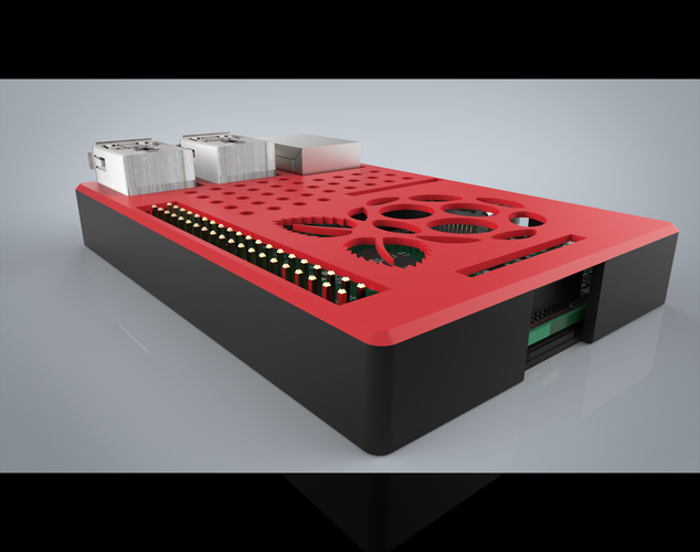 If your motors come without any wires attached you’ll need to prepare your own wires and solder these onto the tiny motors. Soldering small parts can be tricky; you will need a steady hand and something to hold the motors while you hold the solder in one hand and the soldering iron in the other.
- Prepare the wires for soldering. Cut four strips of red wire 100mm long each and another four strips of black wire. We should have a pair of black and red wires for each motor.
- Strip wires. Strip about 4mm of wire from each end, exposing the copper wire. A good pair of wire strippers is an essential part of a maker's toolbox.
- Add Flux. Apply some flux to one end of the wire that will be soldered. Flux helps the solder run around the part correctly. Even if your solder comes with a flux core, a little extra flux will make soldering much easier.
- Tin the wires by adding a small amount of solder to the wires with your soldering iron.
 Tinning will help the wires solder to the small motor terminals
 - Solder the red wire onto the motor terminal - you’ll notice a small + sign above the terminal that is the positive terminal. Take your time, as this can be tricky if you’ve not done it before.
- Push the wire through the hole in the terminal first to make a good mechanical connection and will help hold the wire in place as you solder, then solder the wire to the terminal.
- Repeat the last step for the black wire but this time solder the black wire to the Negative terminal on the motor.
- Twist red and black wires for strength. This will help strengthen the connection if you accidentally tug on the wires.
9. Solder the 40 pin header and 20 pin header to the Explorer pHat
(Image credit: Tom's Hardware)Assembly
The assembly part of the build won’t take long as it only involves screwing the four motor holders into the chassis using the M2.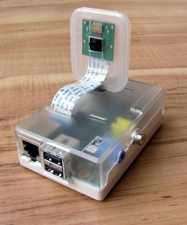 5 screw and nuts. Then we screw the standoffs into the chassis and Raspberry Pi Zero 2 W, and finally, we attach the Camera holders and top section.
1. Push each motor into a 3D printed motor holder. The motor holders ensure that the motor remains in place on Explora’s chassis. They also offer mechanical rigidity so that the motors do not move position in use.
2. Put a nut into each hexagonal pocket on the motor holder, then screw it from the top side of the chassis through to the motor holder into the nut. Don’t over-tighten as you’ll end up splitting the chassis. This will create a substantial connection between the motor holder and the chassis.
(Image credit: Tom's Hardware)3. Add stand-offs to the chassis by screwing four M2.5 screws into the bottom of the chassis, and screw on a stand-off barrel onto the exposed screw thread until it becomes tight against the chassis.
4. Add four stand-offs to the Raspberry Pi Zero, then attach the Explorer pHat.
5. Screw the Raspberry Pi Zero into the Chassis stand-offs.
6. Push the Camera Holder into the Chassis. You may need to file off some material if it's a tight fit.
7. Push the ultrasonic rangefinder into the Camera Holder.
8. Push the female end of the DuPont wires onto the Rangefinder.
9. Push the male end of the DuPont wires onto Explorer pHATs 5v, GND, Output 1 to Trigger, Input 1 to Echo connections.
10. Push the Camera back into the Chassis.
(Image credit: Tom's Hardware)11. Add the last four stand-offs onto the Raspberry Pi Zero
12. Push the Top section over the two camera holders and screw the last 4 M2.5 screws from the top section into the standoffs
13. Using a velcro strap, secure the battery in place.
(Image credit: Tom's Hardware)14. Push the 4 wheels onto the ends of the motors. The motor axles are D-shaped, be sure to match the alignment of the axle to the wheel before firmly pushing on.
Preparing the Raspberry Pi
The Raspberry Pi needs a suitable OS to run the Python code to control the motors and optionally capture images. When the Raspberry Pi camera first launched a software library called PiCamera was provided to make it simple to capture stills and video. With the most recent release of Raspberry Pi OS ‘Bullseye’, this old library has been replaced with a library called LibCamera, which is not backward compatible with PiCamera. On the 32-bit release of Bullseye you can choose a legacy camera option from raspi-config, however, this option is not available on the 64bit release.
1. Using the official Raspberry Pi Imager tool, flash the latest 32-bit OS to a micro SD card. We use the 32-bit version of Raspberry Pi OS because the PiCamera library is currently not compatible with the 64-bit version of Raspberry Pi OS.
2. Put the micro SD card into the SD card reader slot on your computer.
(Image credit: Tom's Hardware)3. Select the micro SD card from the Raspberry Pi imager Storage menu.
(Image credit: Tom's Hardware)4. Click the Advanced (cog) button, and add your Wi-Fi SSID and password details to enable the Raspberry Pi to connect to the wifi automatically.
(Image credit: Tom's Hardware)5. Click on Enable SSH and create a username and password. SSH enables a remote to the Raspberry Pi using a terminal without the need for a monitor, keyboard, or mouse.
6. Click Write to begin flashing the image to the micro SD card.
(Image credit: Tom's Hardware)7. Insert the micro SD card into the Raspberry Pi and then power up the Raspberry Pi via the power bank.
Connecting to the Pi
1. Find out the IP address of your Raspberry Pi - you can usually do this from your router (or wherever your router gets its IP addresses from, or by typing:
ssh pi@raspberrypi.local
- where `pi` is the username you created earlier in step 5 above.
2. Launch Terminal - if you’re on Windows, you’ll need to use some terminal software such as Putty (https://www.putty.org). Mac and Linux computers have terminal build-in.
(Image credit: Tom's Hardware)3. SSH to the Raspberry Pi - Type `ssh [email protected]>` into the terminal to connect to the Pi. Linux / Mac users can use the following to SSH into the Pi. If you know the IP address you cal also type `ssh@<ipaddress>`, where <ipaddress> is the IP address of the Raspberry Pi.
ssh [email protected](Image credit: Tom's Hardware)
From the Raspberry Pi terminal, clone the Explora software repository. The software is on Github, and we can use the git clone command to download the latest version to our Raspberry Pi:
git clone https://www.github.com/kevinmcaleer/explora(Image credit: Tom's Hardware)
4. Install the Explorer Library via Pimoroni’s online install script.
curl https://get.pimoroni.com/explorerhat | bash
4. From the Raspberry Pi terminal, clone the Explora software repository. The software is on Github, and we can use the git clone command to download the latest version to our Raspberry Pi:
curl https://get.pimoroni.com/explorerhat | bash
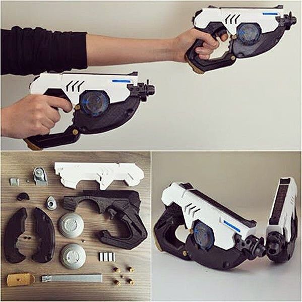
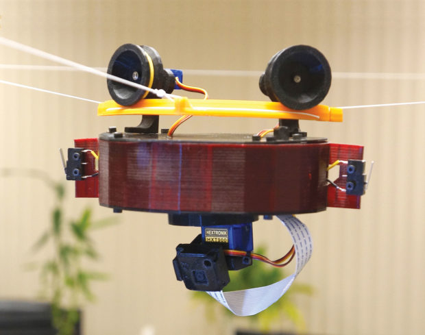
You should now have a fully assembled Explora robot on your desk, ready to receive your first Explora Python program. You can expand the capabilities of Explora by adding a LIDAR laser scanner and Raspberry Pi Camera such as the ones in the picture below.
Next, we create some programs for Explora in Python to move the robot around and detect objects.
- 1
Current page: Building Explora Robot
Next Page Programming Explora Robot
Topics
Raspberry Pi
Tom's Hardware is part of Future US Inc, an international media group and leading digital publisher.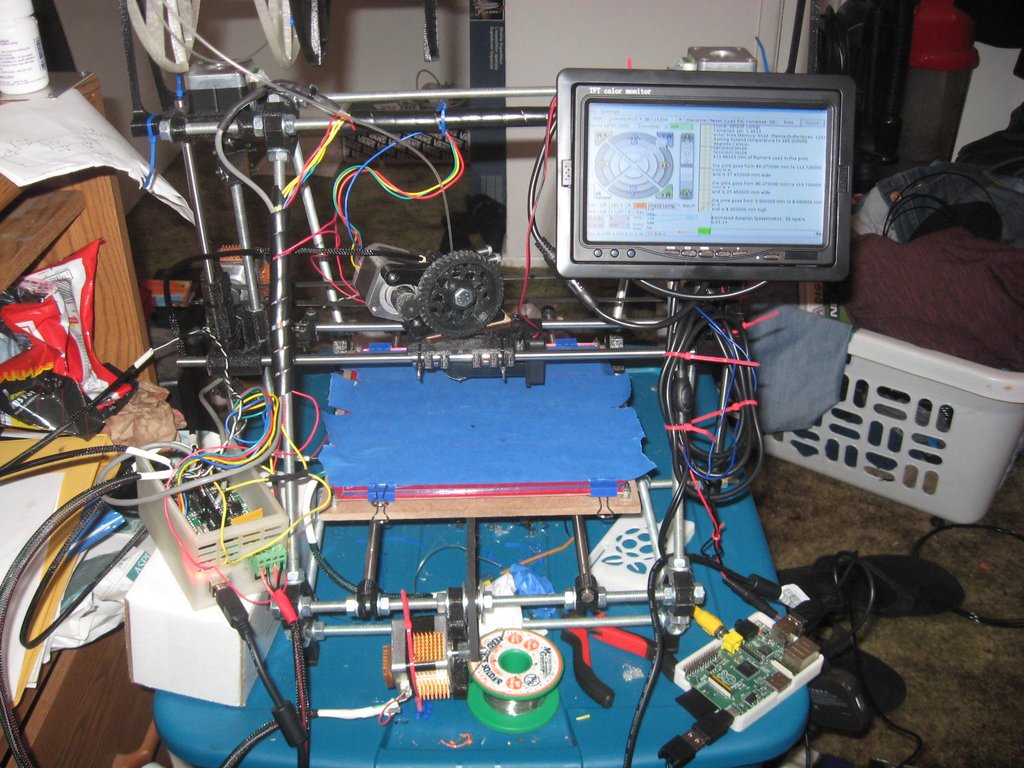 Visit our corporate site .
© Future US, Inc. Full 7th Floor, 130 West 42nd Street, New York, NY 10036.
Top 3D Printing Projects With Your Raspberry Pi
Published on February 18, 2021 by Amelia H.
A Raspberry Pi is a credit card sized computer that can be bought for as a little as $30. The device was invented in an endeavor to encourage people to learn how to program computers. A Raspberry Pi can run on an SD card like those used by cameras and can be charged using a USB phone charger. By combining the accessibility and freedom of manufacturing with 3D printing and programming with Raspberry Pi, the maker community has come up with several innovative projects that you can try out at home! From ventilators, to tablets and telescopes, we’ve compiled a list of some of our favorite 3D printing x Raspberry Pi projects.
Covid-19 Ventilator
In response to the prospective, and later confirmed, shortage of ventilators in countries across the world stemming from the pandemic, MakAir developed a mass-producible open-source Covid-19 ARDS ventilator. The ventilator itself can be 3D printed with either an SLS, SLA, or FDM 3D printer. MakAir recommend using an SLS 3D printer such as the HP Multi Jet Fusion. The ventilator’s control unit comprises a Raspberry Pi 4 computer, plugged to a Raspberry Pi Touch Display. You can find the full instructions HERE.
Wouldn’t it be amazing if there was a robot meant for space that could be built with a simple 3D printer? Well that’s exactly what Maximilian Ehrhardt and Miro Voellmy from the Planetary Robotics Laboratory of the European Space Agency wanted to create. Named ExoMy, the Martian rover can be 3D printed for only $250. It is composed of 3D printable parts, servomotors, screws as well as a Raspberry Pi 4 and a v2 camera module. Thanks to the affordability and accessibility of 3D printing technology and Raspberry Pi, this project makes space robotics more widely available.
The Wave SpeakerThe speaker, named The Wave because of its shape, was first designed as part of an engineering and design course at the Technical University of Denmark. The course offers students the opportunity to develop and design new prototypes, such as this speaker with its unusual geometry, using additive manufacturing. Printed in 3D, The Wave is powered by a Raspberry PI and connects WIFI, allowing music to be played on the speaker directly from the user’s phone. For those who wish to use additive manufacturing to create their own speaker you can find the instructions on Thingiverse!
This telescope is a fusion of Raspberry Pi and Icon. The PiKon is the result of a collaboration between the University of Sheffield and Alternative Photonics. Designed for the Festival of the Mind, PiKon aims to demonstrate what citizens are able to do with new, low-cost technologies (3D printing and a Raspberry Pi). Apart from the primary and secondary mirrors, all the components of the telescope were 3D printed. The telescope prototype is connected to a Raspberry Pi with a 3D printed adapter. The Raspberry Pi is equipped with an infrared camera, making it possible to photograph the night sky, but also to record the shots. If you are passionate about astrophotography and new technologies, do not hesitate to find all the information necessary to build your own PiKon HERE.
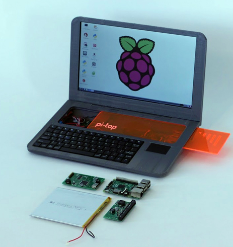
If you have a Raspberry Pi and a 3D printer, you can create your own laptop with this Thingiverse file. As you can imagine, this is not an easy project and basic knowledge in electronics is needed. You’ll also need screwdrivers, wire cutters and a soldering iron in order to build the laptop. After you get all the tools, you will need to follow the instructions to assemble the laptop step by step. To achieve this, the author specifies that he used the Prusa Steel 3D printer to create the parts, with a resolution of 0.2 and a filling of 20%.
A 3D Printed TabletSimilarly, our next project is complex but equally impressive. In order to build this tablet, you will of course need a 3D printer and a Raspberry Pi as main elements. The project requires a few other parts which the author details on the website.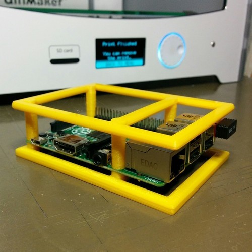 If you want to get started with this printing project, keep in mind that the commitment is fairly long term. Nonetheless, we encourage you to try to create your own tablet and share the result with us! You can find the website with all the assembly instructions, as well as a video explaining all the steps you need to follow HERE.
Dual Redundant CubeSat Flight Computer
Our next model is a dual redundant CubeSat flight computer. Redundancy increases the reliability of hardware in space so the idea is that if one system breaks down or no longer responds, another can take over and continue its task. Student Alex Pirie has been working on this project since 2014, and decided to turn to the Raspberry Pi for its low cost and compact size. You can find more information HERE.
Video Glasses
With this project you can turn any pair of glasses into a wearable mounted computer powered by Raspberry Pi. You’ll need a few things to get you started: NTSC/PAL video glasses; a Raspberry Pi; miniature wireless usb keyboard with touchpad; 3d printer; flat pliers; 30awg wire wrap; a heat shrink pack; screwdriver set; and a composite video cable.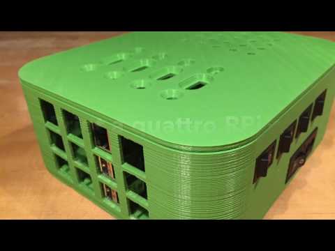 For the 3D printing aspect, there are just eight parts that can be printed and assembled in about two hours. The final part acts as a snap-fit enclosure that houses the components inside the NTSC/PAL video glasses. You can download the STL files and instructions HERE.
Build your own 3D Scanner
This project is a little different in that it does not necessarily need to be made with a 3D printer (though it can be!) but it will definitely come in handy for any 3D printing projects. In this step-by-step guide, users can learn how to make their own 3D scanner, with the updated versions even large enough to scan an entire adult person (up to 2m tall). To get started you’ll just need Raspberry Pis, PI cameras, SD cards, Led Strips and powerful power supplies, though the mounts, tripods and other parts could be 3D printed. There is assembly required and some coding (the owner provides python script that can be downloaded), but once you’re done you can make your own 3D scans of your loved ones which you can then 3D print! If you’re interested, the guide and the files can be found HERE.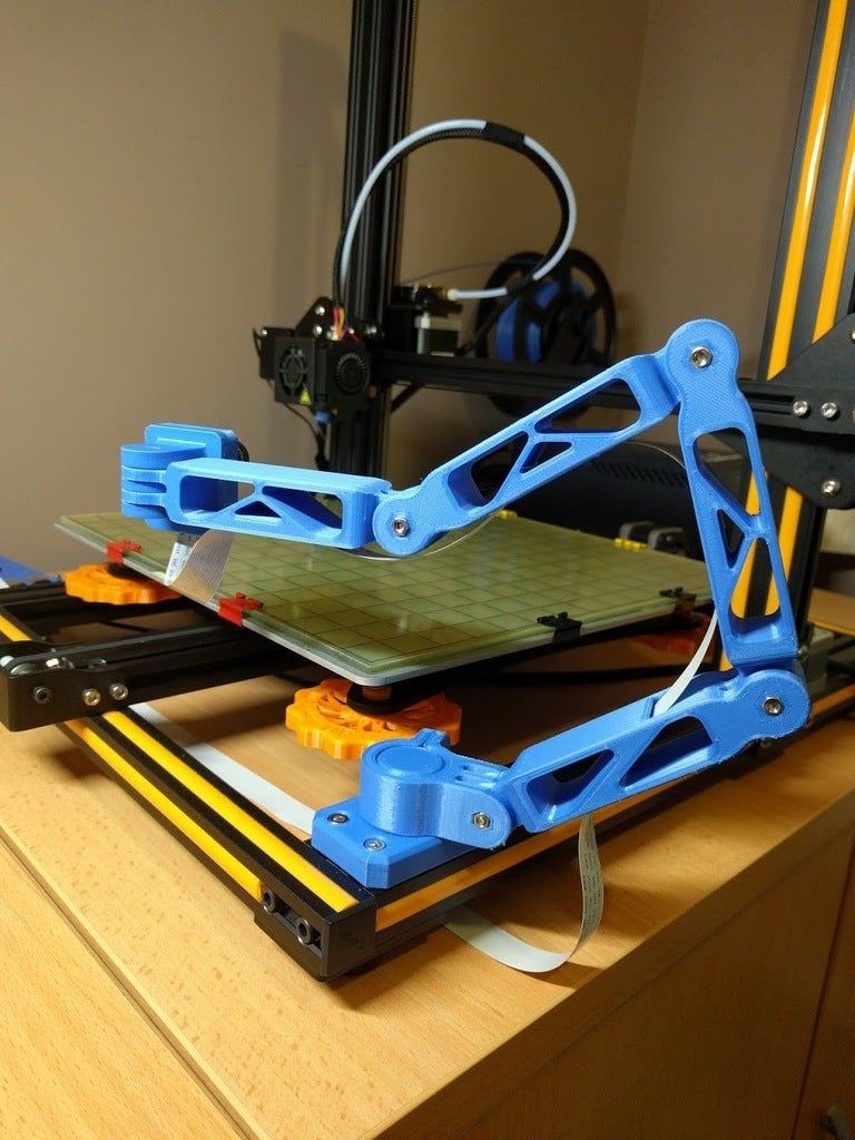
DIY desktop laser cutter and engraver
According to the page on Thingiverse, FABOOL Laser Mini is an open-source, ready-to-assemble desktop laser cutter and engraver. You will need a hex wrench and spanner, but assembly itself will only take about two hours. The end product has a work area of 300x230mm. Raspberry Pi is one of the compatible software, though others are also supported, including Windows, Mac OS X, and Linux. This updated version has improved usability, a stylish design and about ¼ of the previous assembly time. You can find the files HERE.
What do you think of these 3D printing and Raspberry Pi projects? Let us know in a comment below or on our Linkedin, Facebook and Twitter pages! Sign up for our free weekly Newsletter here, the latest 3D printing news straight to your inbox!
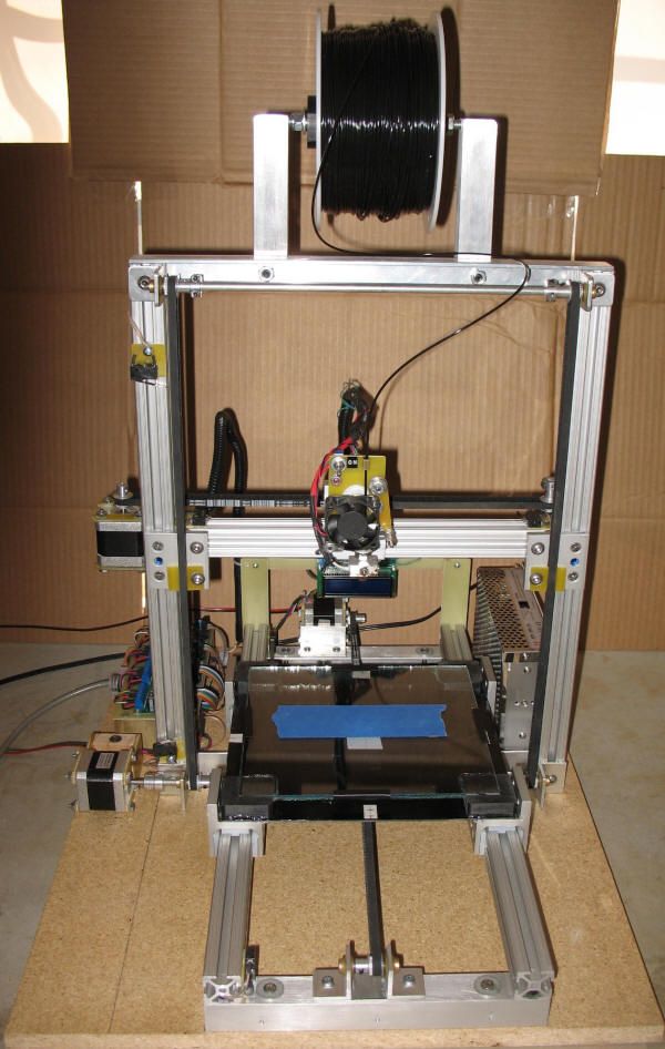
Building a home 3D printer with your own hands: recommendations from personal experience
3D printing and assembly of 3D printers is my hobby and passion. Here I will not share detailed diagrams and drawings, there are more than enough of them on specialized resources. The main goal of this material is to tell you where to start, where to dig and how to avoid mistakes in the process of assembling a home 3D printer. Perhaps one of the readers will be inspired by applied engineering achievements.
Why do you need a 3D printer? Use cases
I first came across the idea of 3D printing back in the 90s when I was watching the Star Trek series. I remember how impressed I was by the moment when the heroes of the cult series printed the things they needed during their journey right on board their starship. They printed anything: from shoes to tools. I thought it would be great someday to have such a thing too. Then it all seemed something incredible. Outside the window are the gloomy 90s, and the Nokia with a monochrome screen was the pinnacle of progress, accessible only to a select few.
Years passed, everything changed.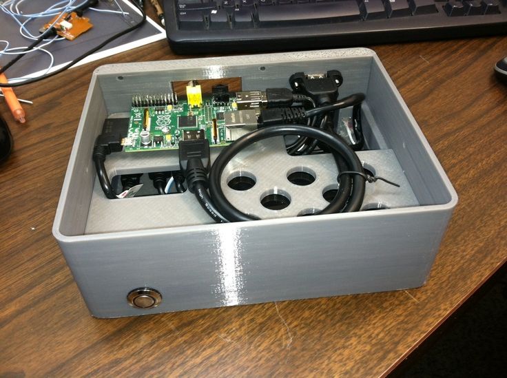 Around 2010, the first working models of 3D printers began to appear on sale. Yesterday's fantasy has become a reality. However, the cost of such solutions, to put it mildly, discouraged. But the IT industry would not be itself without an inquisitive community, where there is an active exchange of knowledge and experience and who just let them dig into the brains and giblets of new hardware and software. So, drawings and diagrams of printers began to surface more and more often on the Web. Today, the most informative and voluminous resource on the topic of assembling 3D printers is RepRap - this is a huge knowledge base that contains detailed guides for creating a wide variety of models of these machines.
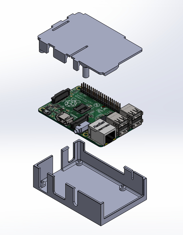
I assembled the first printer about five years ago. My personal motivation to build my own device is quite prosaic and based on several factors. Firstly, there was an opportunity to try to realize the old dream of having your own device, inspired by a fantasy series. The second factor is that sometimes it was necessary to repair some household items (for example, a baby stroller, car elements, household appliances and other small things), but the necessary parts could not be found.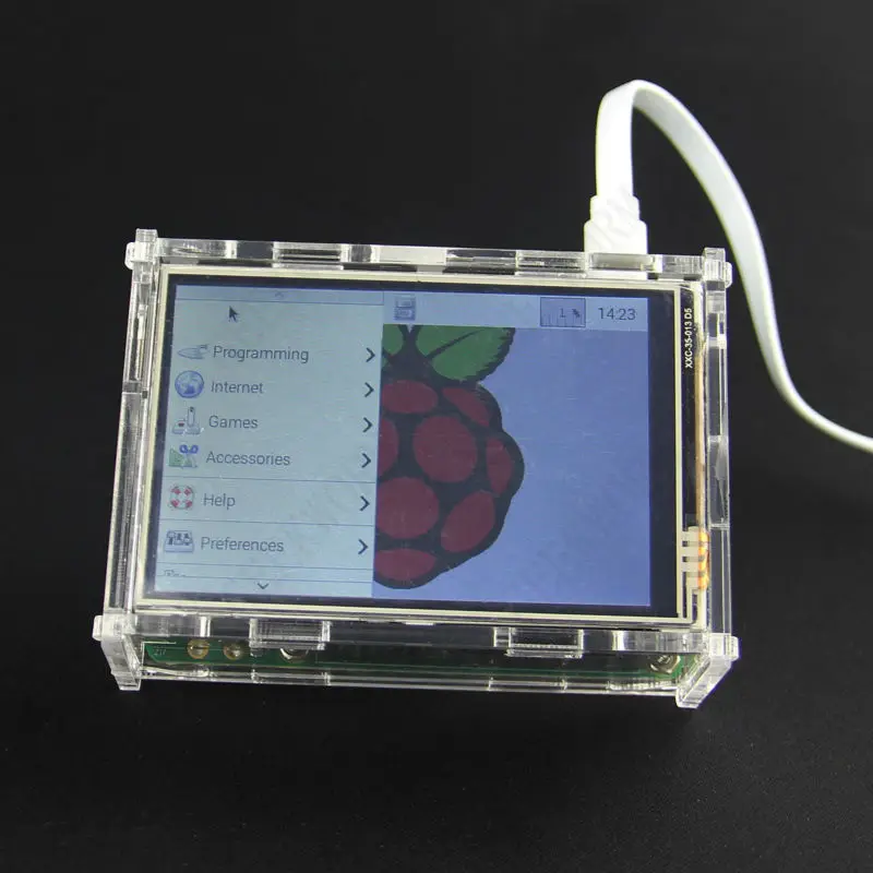 Well, the third aspect of the application is "near-working". On the printer, I make cases for various IoT devices that I assemble at home.
Agree, it is better to place your device based on Raspberry Pi or Arduino in an aesthetically pleasing "body", which is not a shame to put in an apartment or take to the office, than to organize components, for example, in a plastic bowl for food. And yes, you can print parts to build other printers :)
There are a lot of scenarios for using 3D printers. I think everyone can find something of their own.
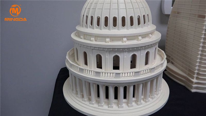
A complex part in terms of drawing that I printed on my printer. Yes, it's just a figurine, but it has many small elements
Ready solution vs custom assembly
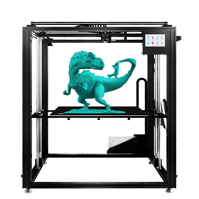
When a technology has been tested, its value in the market decreases markedly. The same thing happened in the world of 3D printers. If earlier a ready-made solution cost simply sky-high money, then today acquiring such a machine is more humane for the wallet, but nevertheless not the most affordable for an enthusiast. There are a number of solutions already assembled and ready for home use on the market, their price range ranges from $500-700 (not the best options) to infinity (adequate solutions start from a price tag of about $1000). Yes, there are options for $150, but we, for understandable, I hope, reasons, will not dwell on them.
In short, there are three cases to consider a finished assembly:
- when you plan to print not much and rarely;
- when print accuracy is critical;
- you need to print molds for mass production of parts.
There are several obvious advantages to self-assembly. The first and most important is cost. Buying all the necessary components will cost you a maximum of a couple of hundred dollars. In return, you will receive a complete 3D printing solution with the quality of manufactured products acceptable for domestic needs. The second advantage is that by assembling the printer yourself, you will understand the principles of its design and operation. Believe me, this knowledge will be useful to you during the operation of even an expensive ready-made solution - any 3D printer needs to be serviced regularly, and it can be difficult to do this without understanding the basics.
The main disadvantage of assembly is the need for a large amount of time. I spent about 150 hours on my first build.
What you need to assemble the printer yourself
The most important thing here is the presence of desire. As for any special skills, then, by and large, in order to assemble your first printer, the ability to solder or write code is not critical. Of course, understanding the basics of radio electronics and basic skills in the field of mechanics (that is, "straight hands") will greatly simplify the task and reduce the amount of time that needs to be spent on assembly.
Also, to start we need a mandatory set of parts:
- Extruder is the element that is directly responsible for printing, the print head.
 There are many options on the market, but for a budget build, I recommend the MK8. Of the minuses: it will not be possible to print with plastics that require high temperatures, there is noticeable overheating during intensive work, which can damage the element. If the budget allows, then you can look at MK10 - all the minuses are taken into account there.
 - Processor board. The familiar Arduino Mega is well suited. I didn't notice any downsides to this solution, but you can spend a couple of dollars more and get something more powerful, with a reserve for the future.
- Control board. I'm using RAMPS 1.4 which works great with the Arduino Mega. A more expensive but more reliable board is Shield, which already combines a processor board and a control board. In modern realities, I recommend paying attention to it. In addition to it, you need to purchase at least 5 microstep stepper motor controllers, for example - A4988. And it's better to have a couple of these in stock for replacement.

- Heated table. This is the part where the printed element will be located. Heating is necessary due to the fact that most plastics will not adhere to a cold surface. For example, for printing with PLA plastic, the required surface temperature of the table is 60-80°C, for ABS - 110-130°C, and for polycarbonate it will be even higher
There are also two options for choosing a table - cheaper and more expensive. Cheaper options are essentially printed circuit boards with preheated wiring. To operate on this type of table, you will need to put borosilicate glass, which will scratch and crack during operation. Therefore, the best solution is an aluminum table. - Stepper motors. Most models, including the i2 and i3, use NEMA 17 size motors, two for the Z axis and one each for the X and Y axes. Finished extruders usually come with their own stepper motor. It is better to take powerful motors with a current in the motor winding of 1A or more, so that there is enough power to lift the extruder and print without skipping steps at high speed.
- Basic set of plastic fasteners.
- Belt and gears to drive it.
Examples of elements appearance: 1) MK8 extruder; 2) Arduino processor board; 3) RAMPS control board; 4) motor controllers; 5) aluminum heated table; 6) NEMA 17 stepper motor; 7) a set of plastic fasteners; 8) drive gears; 9) drive belt
This is a list of items to be purchased. Hardcore users can assemble some of them themselves, but for beginners, I strongly recommend purchasing ready-made solutions.
Yes, you will also need various small things (studs, bearings, nuts, bolts, washers ...) to assemble the case. In practice, it turned out that using a standard m8 stud leads to low printing accuracy on the Z axis. I would recommend immediately replacing it with a trapezoid of the same size.
M8 trapezoid stud for Z axis, which will save you a lot of time and nerves. Available for order on all major online platforms
You also need to purchase customized plastic parts for the X axis, such as these from the MendelMax retrofit kit.
Most parts available at your local hardware store. On RepRap you can find a complete list of necessary little things with all sizes and patterns. The kit you need will depend on the choice of platform (we'll talk about platforms later).
What's the price
Before delving into some aspects of the assembly, let's figure out how much such entertainment will cost for your wallet. Below is a list of parts required for purchase with an average price.
Platform selection
The community has already developed a number of different platforms for assembling printers - the most optimal case designs and the location of the main elements, so you do not have to reinvent the wheel.
i2 and i3 are key platforms for self-assembly printer enclosures. There are also many modifications of them with various improvements, but for beginners, these two classic platforms should be considered, since they do not require special skills and fine-tuning.
Actually, illustration of platforms: 1) i2 platform; 2) i3 platform
On the plus side of i2: it has a more reliable and stable design, although it is a little more difficult to assemble; more opportunities for further customization.
The i3 variant requires more special plastic parts to be purchased separately and has a slow print speed. However, it is easier to assemble and maintain, and has a more aesthetically pleasing appearance. You will have to pay for simplicity with the quality of printed parts - the body has less stability than i2, which can affect print accuracy.
Personally, I started my experiments in assembling printers from the i2 platform. She will be discussed further.
Assembly steps, challenges and improvements
In this block, I will only touch on the key assembly steps using the i2 platform as an example. Full step by step instructions can be found here.
The general scheme of all the main components looks something like this. There is nothing particularly complicated here:
I also recommend adding a display to your design. Yes, you can easily do without this element when performing operations on a PC, but it will be much more convenient to work with the printer this way.
Understanding how all components will be connected, let's move on to the mechanical part, where we have two main elements - a frame and a coordinate machine.
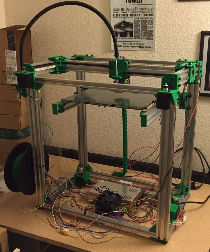
Assembling the frame
Detailed frame assembly instructions are available on RepRap. Of the important nuances - you will need a set of plastic parts (I already talked about this above, but I'd better repeat it), which you can either purchase separately or ask your comrades who already have a 3D printer to print.
The frame of the i2 is quite stable thanks to its trapezoid shape.
This is how the frame looks like with parts already partially installed. For greater rigidity, I reinforced the structure with plywood sheets
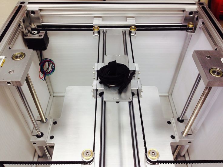
Coordinate machine
An extruder is attached to this part. The stepper motors shown in the diagram above are responsible for its movement. After installation, calibration is required along all major axes.
Important - you will need to purchase (or make your own) a carriage for moving the extruder and a mount for the drive belt. Drive belt I recommend GT2.
The carriage printed by the printer from the previous picture after it has been assembled. The part already has LM8UU bearings for guides and belt mount (top)
Calibration and adjustment
So, we completed the assembly process (as I said, it took me 150 hours) - the frame was assembled, the machine was installed. Now another important step is the calibration of this very machine and extruder. Here, too, there are small subtleties.
Setting up the machine
I recommend calibrating the machine with an electronic caliper. Do not be stingy with its purchase - you will save a lot of time and nerves in the process.
The screenshot below shows the correct constants for the Marlin firmware, which must be selected in order to set the correct number of steps per unit of measure. We calculate the coefficient, multiply it, substitute it into the firmware, and then upload it to the board.
Marlin 9 firmware constants0022
For high-quality calibration, I recommend relying on larger numbers in measurements - take not 1-1.5 cm, but about 10. So the error will be more noticeable, and it will become easier to correct it.
Calibrating the extruder
When the frame is assembled, the machine is calibrated, we start setting up the extruder. Here, too, everything is not so simple. The main task of this operation is to correctly adjust the supply of plastic.
If underfeeding, the printed test item will have noticeable gaps, like test die 1. Conversely, the result will look bloated if plastic is overfed (dice 2)
Getting Started Printing
It remains for us to run some CAD or download ready-made .stl, which describe the structure of the printed material. Next, this structure needs to be converted into a set of commands understandable to our printer. For this I use the Slicer program. It also needs to be set up correctly - specify the temperature, the size of the extruder nozzle. After that, the data can be sent to the printer.
Slicer interface
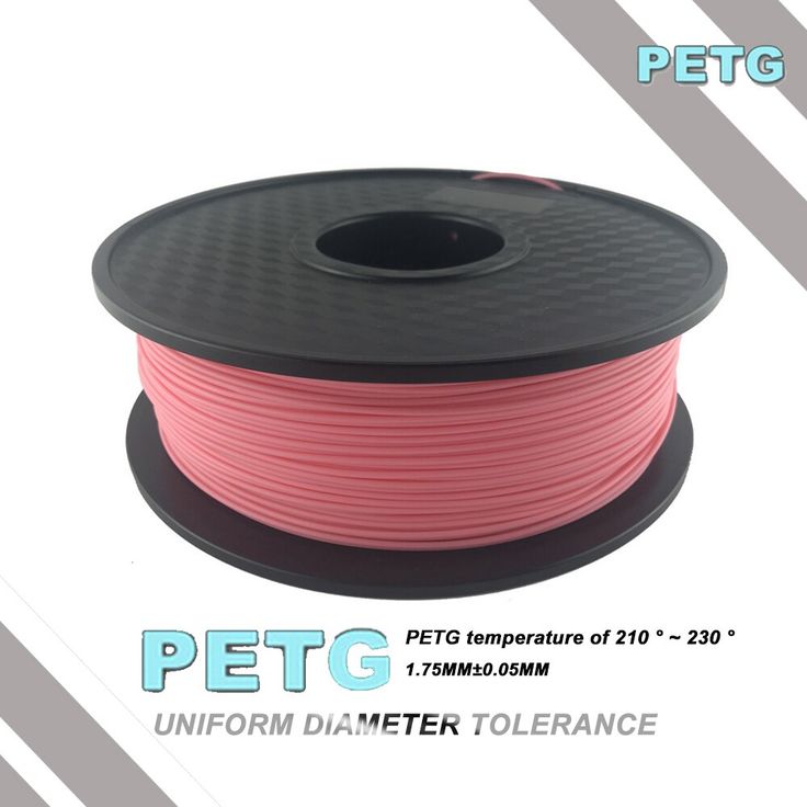
As a raw material for printing, I recommend starting with regular ABS plastic - it is quite strong, products made from it are durable, and it does not require high temperatures to work with. For comfortable printing with ABS plastic, the table must be heated to a temperature of 110-130 ° C, and the extruder nozzle - within 230-260 ° C.
Some important details. Before printing, calibrate the machine along the Z axis. The extruder nozzle should be approximately half a millimeter from the table and ride along it without distortion. For this calibration, a regular sheet of A4 paper inserted between the nozzle and the surface of the heated table is best suited. If the sheet can be moved with little effort, the calibration is correct.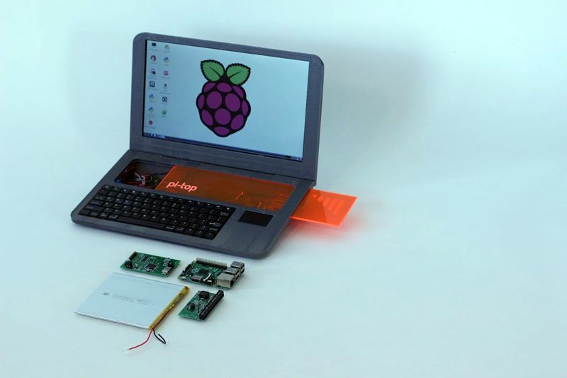
Another thing to keep in mind is the surface treatment of the heated table. Usually, before printing, the surface of the table is covered with something that hot plastic sticks to well. For ABS plastic, this can be, for example, Kapton tape. The disadvantage of adhesive tape is the need to re-glue it after several printing cycles. In addition, you will have to literally tear off the adhering part from it. All this, believe me, takes a lot of time. Therefore, if it is possible to avoid this fuss, it is better to avoid it.
An alternative option that I use instead of scotch tape is to apply several layers of ordinary light beer, followed by heating the table to 80-100 ° C until the surface is completely dry and re-applying 7-12 layers. It is necessary to apply the liquid with a cloth moistened with a drink. Among the advantages of this solution: ABS plastic separates from the table on its own when it cools down to about 50 ° C and is removed without effort, the table does not have to be peeled off, and one bottle of beer will last you for several months (if you use the drink only for technical purposes :)).
After we have collected and configured everything, we can start printing. If you have an LCD screen, then the file can be transferred for printing using a regular SD card.
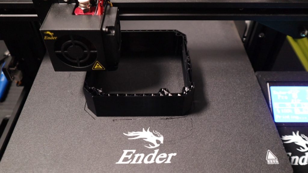
The first results may have bumps and other artifacts - do not worry, this is a normal process of "grinding" the printer elements, which will end after a few print cycles.
Tips to make life easier (and sometimes save money)
In addition to the small recommendations given in the text above, in this section I will also give a short list of tips that will greatly simplify the operation of a 3D printer and the life of its owner.
- Do not experiment with nozzles. If you plan to immediately print from materials that require high temperatures, then it is better to immediately take the MK10 extruder. On MK8, you can "hang" special nozzles that support high-temperature conditions. But such modifications often cause difficulties and require special experience.
 It is better to avoid this fuss on the shore by simply installing the right extruder for you.
 - Add starter relay for heated table. Improving the power supply system for this important printing part with a starter relay will help solve the known problem of RAMP 1.4 - overheating of the transistors that control the power of the table, which can lead to failure of the board. I made this upgrade after having to throw away a few RAMPS 1.4s.
- Select the correct filament diameter for printing. I recommend using 1.75mm plastic for MK8 and MK10. If we take plastic, for example, 3 mm, then the extruder simply does not have enough strength to push it at an acceptable speed - everything will be printed much longer, and the quality will drop. ABS plastic is ideal for MK8, MK10 will be able to produce products from polycarbonate.
- Use only new and precise X and Y guides. Print quality will be affected. It is difficult to count on good quality with bent or deformed guides along the axes.
- Take care of cooling. During my experiments with various extruders, the MK10 showed the best results - it prints quite accurately and quickly. The MK10 can also print plastics that require a higher print temperature than ABS, such as polycarbonate. Although it is not as prone to overheating as its younger brother MK8, I still recommend taking care of its cooling by adding a cooler to your design. It must be permanently enabled, this option can be configured in Slicer. You can also add coolers to keep the stepper motors at an acceptable temperature, however, make sure that their air flows do not fall on the printed part, as this can lead to its deformation due to too rapid cooling.
- Consider heat retention. Yes, on the one hand, we are struggling with overheating of the elements. On the other hand, a uniform temperature around the printer will contribute to high-quality printing (the plastic will be more pliable). To achieve a uniform temperature, you can put our printer, for example, in a cardboard box.
 The main thing is to connect and configure the coolers before that, as described above.
 - Consider insulating your desk. Heated table heats up to high temperatures. And if part of this heat leaves properly, heating the printed part, then the second part (from below) just goes down. To concentrate the heat from the table onto the part, you can perform an operation to insulate it. To do this, I simply attach a cork mouse pad to its bottom using stationery clips.
Pins
I am sure that during the assembly process you will encounter a number of difficulties specific to your project. Neither this text nor even the most detailed guides will insure against this.
As I wrote in the introductory part, the above does not claim the status of a detailed assembly manual. It is almost impossible to describe all the stages and their subtleties within the framework of one such text. First of all, this is an overview material that will help you prepare for the assembly process (both mentally and financially), understand whether you personally need to bother with self-assembly - or give up on everything and buy a ready-made solution.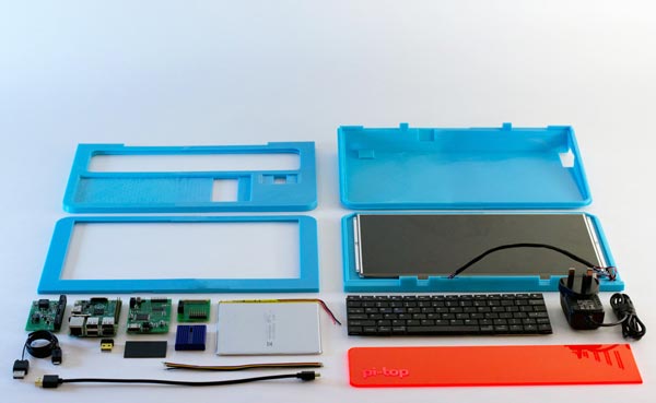
For me, assembling printers has become an exciting hobby that helps me solve some issues in home and work affairs, take my mind off programming and do something interesting with my own hands. For my children - entertainment and the opportunity to get unusual and unique toys. By the way, if you have children whose age allows them to mess around with such things, such an activity can be a good help for entering the world of mechanics and technology.
For everyone, the vectors of using 3D printers will be very different and very individual. But, if you decide to devote your personal time to such a hobby, believe me, you will definitely find something to print :)
I will be glad to answer comments, remarks and questions.
What to read/see
- what can be printed;
- 3D printer forum;
- RepRap community site with model descriptions and assembly instructions;
- printer that prints electronics.
Subscribe to the Telegram channel "DOU #tech" so you don't miss new technical articles.
Topics: DIY, embedded, tech
12 Raspberry Pi projects for your 3D printer
There is probably no better gadget for your DIY projects than a 3D printer. With a device capable of assembling every case, frame, bracket and more, this is an essential part of the kit.
Likewise, the Raspberry Pi is also a vital tool in the tech wizard's arsenal, suitable for everything from home media centers and smart home control. to launch into space!
So what happens when you put these two DIY staples together? Let's take a look at these 12 Raspberry Pi designs that are available for 3D printing.
Game Projects for Raspberry Pi
PiGrrl Nintendo Game Boy Clone
Perhaps one of the most popular uses for the Raspberry Pi is as a retro style game center and this project takes the idea a step further by focusing emulation on one platform and creating suitable case.
PiGrrl is, of course, a Nintendo Game Boy clone developed by LadyAda and you can find the full set of instructions on the Adafruit website, which also includes links to any additional hardware you may need.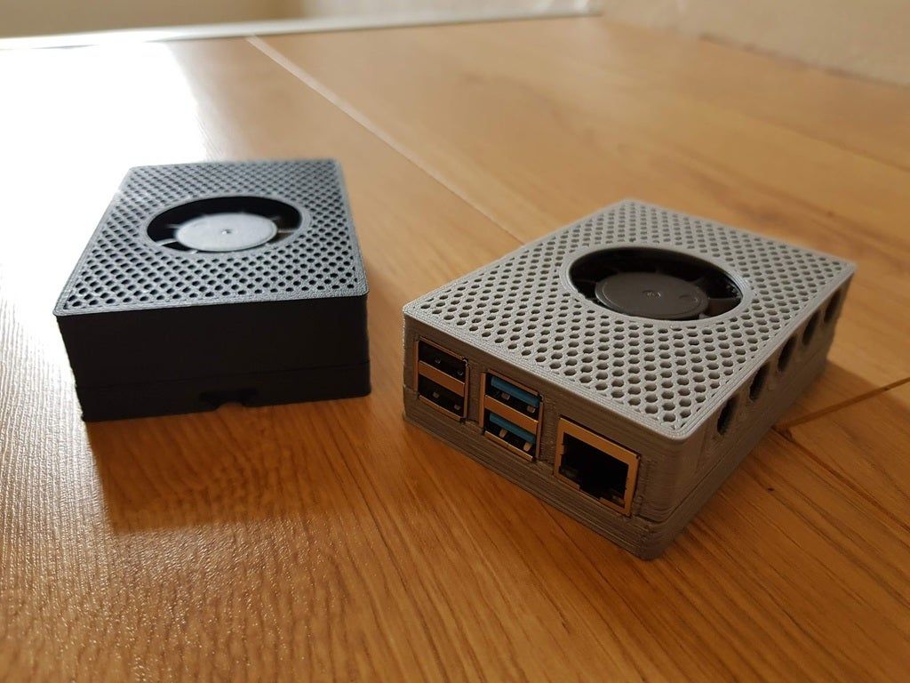 This build uses a cannibalized Nintendo game controller, but there are alternatives to this. We are particularly impressed with the quality of the Game Boy-esque 3D printed case.
Super Game Pi, Game Boy Advance Clone
Still in clone territory, Adafruit also released instructions for what they call the Super Game Pi, which is essentially a clone of the 2001 handheld Game Boy Advance.
The 3D printer file contains more buttons than PiGrrl, but again relies on a cannibalized SNES controller. Just as fun as PiGrrl, it also has a larger screen.
Game Boy Nano
Another great 3D printer project for your Raspberry Pi, based on the Pi Zero, the design of which can be downloaded from Thingverse.
While there are no formal details for this build online, it seems to require a small display and a compact controller, though you might prefer to just add a dummy set of controls and connect a USB or Bluetooth controller to the Pi Zero as a USB. The port remains open for this assembly.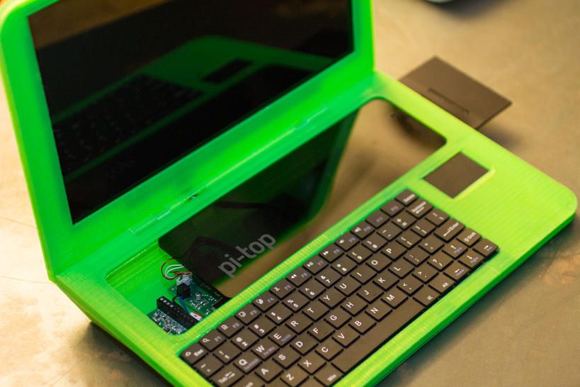
Google Glass with your Raspberry Pi
Want to know all the facts and figures about every place you visit? Google Glass may have taken a backseat now, will be back, but it's a project that can be combined with a Raspberry Pi as the brain, with a 3D printer providing a home for the display, complete with a clip to attach it to glasses!
The 3D print file for your own Google Class replica can be found on Thingiverse, while the display is probably the most important component, in this case cannibalized from a pair of immersive TV glasses.
We're not saying you won't get the same level of turmoil and ridicule as Google Glass, but it's worth it!
Raspberry Pi Laptops
You may know that Pi Top started life as a project for 3D printed laptops for Raspberry Pi devices before a successful Kickstarter campaign brought them commercial success - but it's not the only Raspberry Pi laptop.
Mobile Pi-To-Go
Not quite a laptop like the Pi Top, the Pi-To-Go is nonetheless an impressive project with a small flip-out display and keyboard thanks to this project file from Thingiverse.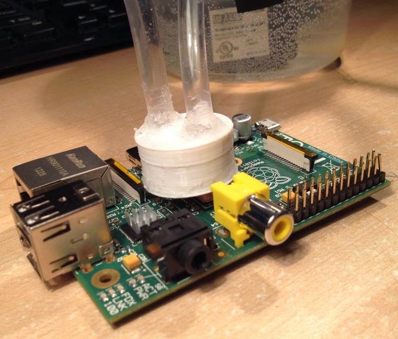
See it in action here.
The bottom of the Pi-To-Go is filled with batteries removed from an old Dell Latitude D600 laptop battery, and behind the screen is a pirated 64GB SSD card.
This looks like a great project to try; see full guide for details.
Raspberry Pi Desktop Cases
We've already told you how the Raspberry Pi can be used as a desktop computer. so it makes sense to create a desktop case for your little computer.
PiBook
The PiBook ( 3D printed file ) is a Raspberry Pi in the form of a desktop computer, with a base unit and a top-mounted display.
Despite the name, the PiBook doesn't look like a book (at least it looks like an Apple Lisa), but it should still satisfy your need to stick a Raspberry Pi into what you just typed.
3D Printable Raspberry Pi Tablets
Several designs for Raspberry Pi tablets are in circulation. This is from Adafruit, the file is ready to be downloaded to your Thingverse 3D printer.
The CAD-designed case houses a Raspberry Pi A+ with a 3.5-inch TFT display. The example in the video may not have a touch screen, but there are several versions of the TFT with capacitive overlays available.
For a more standard Raspberry Pi tablet of a usable size, this next Adafruit project uses a Pi 2 (or possibly a Pi 3) and you can download the 3D printed case file from Thingverse.
Amazing 3D Printed Raspberry Pi 9 cases0005
Finally, we're going to take a look at some of the excellent Raspberry Pi cases that can be 3D printed. This is a huge area, so feel free to go out and look for what you think will suit your project or mood. You may notice some of them along the way...
RetroNintastic
This excellent Raspberry Pi case is clearly inspired by the classic Nintendo entertainment system and even has a door that allows access to the Pi's SD card right where the cartridge slot would be.
This is what it looks like in action!
Not bad, we think you will agree. For more retro love, check out the Amiga 3000 and PiStation One case too, and maybe consider bundling them with the RetroPie gaming distribution.
It's Happened: Raspberry Pie
We're sure you'll already be drooling over this amazing looking 3D Raspberry Pi case, which of course interprets (well, almost) the name of the device literally.
Yum.
Want an absolutely literal interpretation? Think 3.141 6 ...
Raspberries are everywhere
While we're talking "literal interpretations", we can drop the "pi" and focus on "raspberries". The Very Berry Pi Case 3000 is one of the most stunning Raspberry Pi cases we've ever seen, and while larger than most, it has plenty of room to insert cables and cards.
Boys Fallout Pip-Boy
While a lot of 3D printing work, this project - which will also require a portable power source for your Raspberry Pi - looks great, and if you're a fan of the Fallout or just want to take your Pi with you wherever you go Come on, this seems to be the perfect case.