Thermocouple for 3d printer
Temperature sensors used in 3D printers
This post will help you understand the differences and the operation of most common temperature sensors used in 3D Printing.
Each type of sensor has many key performance aspects and the goal of this topic is to compare them in details.
Part 1 will explain the most common sensor types and will take a look at the boards.
Part 2 will go in details about the performance between sensors while keeping in mind the 3D printer application.
Part 3 will provide explanations regarding our choice to go with a thermistor. Finally, some common mistakes are explained regarding temperature sensors.
Do not hesitate if you have any comments or suggestions that could improve this blog.
The most common sensor types are the following:
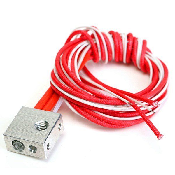
Thermistor
Thermistor are resistor whose resistance changes with temperature. Most commonly used type in 3D printers is NTC, standing for “Negative Temperature Coefficient”. When the temperature increase, the resistance decrease.
They are made from semiconductors, mostly silicon and germanium, and their resistance value can vary by many order of magnitude in their temperature range. A 100k NTC thermistor has a resistance of 100kΩ (100 000Ω) at room temperature (20°C) and drops as low as 100Ω at 300°C.
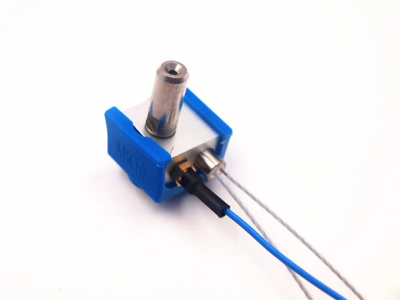
RTD
RTD are very similar to thermistors in term of operation. Rather than having a semiconductor, these are made from metals, mostly platinum, nickel or copper. RTD stands for “Resistance Temperature Detectors”. Most commonly used type in 3D printers is PT100. It has a resistance of 100Ω at 0°C.
With an RTD sensor, the resistance slowly increases with temperature. At 400°C, a PT100 will reach 250Ω. The variation is almost linear.
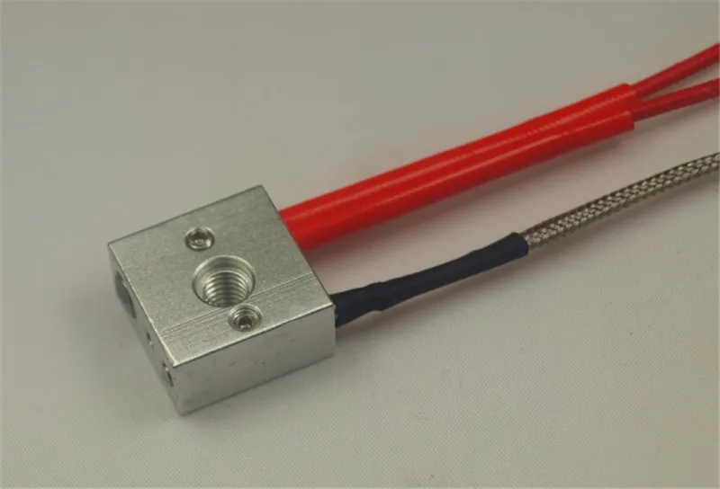
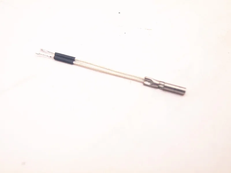
Thermocouple
Thermocouple operates in a totally different way than the other sensors. They are made from two different metals which generate a very small voltage depending on temperature. The most common type used in 3D printers is K and is made from chromel and alumel.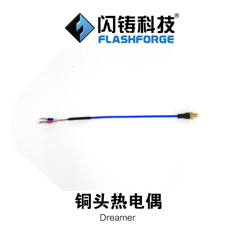
The voltage increase from 0mV to 20mV from 0°C to 500°C. As with PT100, the variation is almost linear at 41 µV/°C.
Please note that the picture shows a welded bead sensor which shouldn’t be used inside a 3D printer. The actual thermocouple should be inside an electrically insulated housing to prevent any noise or ground effect. A housing can be threaded, cylindrical or flat (crimped).
3D Printers manufacturer and motherboard sensor table
Here is a list of 3D printer manufacturers with the sensor types they are using.
The main driving part inside a printer for sensor choice is the motherboard. Each motherboard has unique components which decide what sensor is meant to be used. The most common is the thermistor, which only requires a pull-up resistor to work.
Both RTD and thermocouple require an IC (Integrated Circuit) built for processing their respective signal. These add-on boards are compatible with most boards via I2C and SPI pins for communication, or analog pins. Some specialized boards, such as the Duet Wifi, offer specialized add-on board to enable thermocouple and RTD readings.
| Thermistor | RTD | Thermocouple | |
|---|---|---|---|
| Printers | Prusa, Robo3D, BCN3D, Kossel, Makergear, MendelMax, LulzBot, Printrbot, Mendel90, And many more RepRap… | Ultimaker | MakerBot, FlashForge, CTC, Wanhao Duplicator |
| Motherboards 8 bits | RAMPS, Rambo RUMBA, Melzi, Sanguinololu, Generation 6, Azteeg X1, Azteeg X3 | Ultimaker PCB, Ultimaker Board | MightyBoard, Azteeg X3 Pro, Megatronics |
| Motherboards 32 bits | Smoothieboard, AZSMZ, R2C2, Generation 7, Duet, Replicape | Alligator Board | RADDS |
Thermal sensor performance
Below is a graphical comparison for certain key aspects of temperature sensing in 3D printers.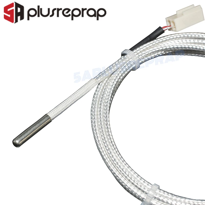 Please note that these values are based on the most common microcontroller configuration used in 3D printing, which is 8 bits microcontroller with 10 bits ADC. Having a higher resolution will improve resolution. Most 32 bits microcontroller benefit from a 12 bits ADC.
Better resolution can be obtained with specialized measurement devices, such as MAX31855, AD595, MAX6675 for thermocouple and MAX31865 for RTD, these are considered with both the RTD and thermocouple, as they are required.
The key performance aspects will be explained and detailed in part 2.
Thermistor
RTD
Thermocouple
Conclusion
Thanks for reading! This part was a short summary of thermal sensors used in 3D printer.
Follow on the next part, there will be a lot of interesting details about performance and in depth analysis!
Source
Sources
Control Engineering : Temperature tutorial
Improving the accuracy of temperature measurements
Overview of temperature sensors
RTD and thermistor comparison
PT100 tolerance classes
Thermocouple accuracy
Thermistor Accuracy
CTC thermocouple or hot end - 3D Printers - Talk Manufacturing
Random3dp
#1
Hey everyone, I think my thermocouple went out on my right extruder.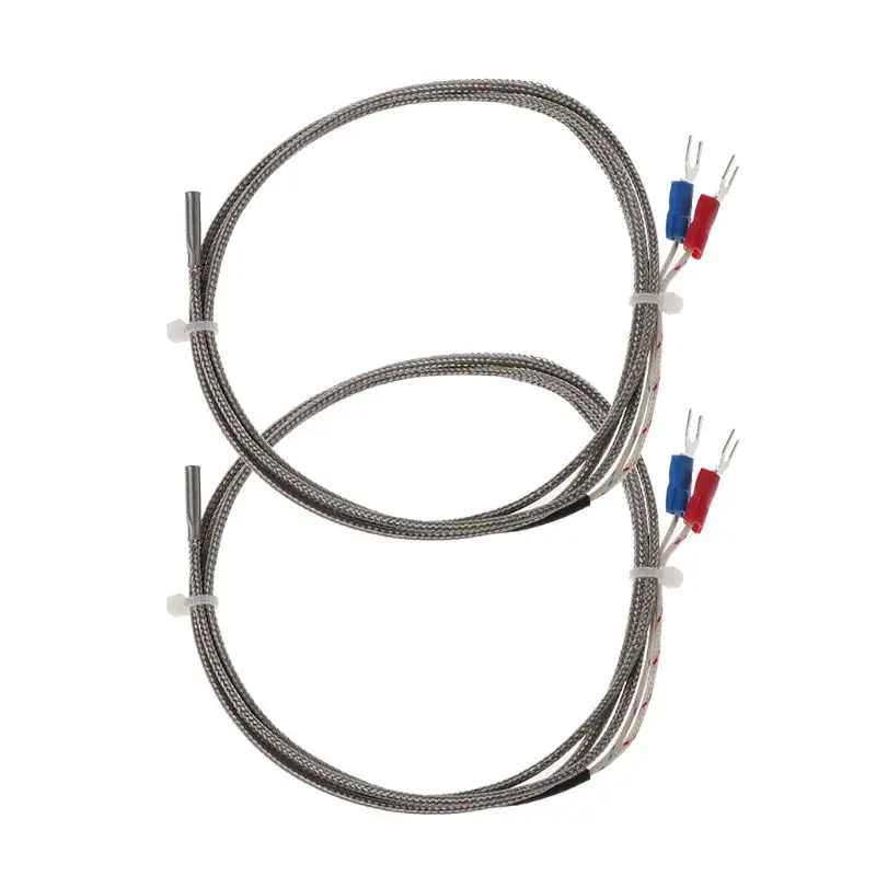 The temp reads NA. I tried turning it off and just printing with the left extruder but it wont do it. So does anyone know what happened to it and where can I get the parts? Ive been looking online for about a week trying to find parts with no success.
4 Likes
bardiir
#2
They got a pretty good support via Skype. It can take a few days until you get an answer but it beats email.
Skype: ammjill (this was in the auction when I bought my printer on eBay)
I paid 25€ for 3 new Thermocouples from them.
conorm125
#3
I have the same issue with the LE, it says to check the wires. However I will need to replace the temperature sensor once we find out what type it is.
BruczLyn
#4
Go on amazon . Com and search for CTC 3d parts. I got mine there. Remember to buy the 24v version.
MakeCoolThings
#5
Ouch, the right? I had the left one go out a couple-few months after I bought the printer… It gave me the same error state on the temp reading, as well as giving me a warning message after a couple seconds every time I turned on the printer.
It was well within the 1-year warranty period, so I just contacted the seller and they sent me another one for the cost of shipping.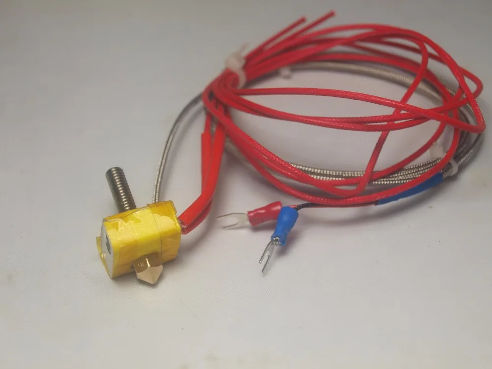 Luckily with the left down, I was able to still print with the right…I guess the opposite isn’t true.
With the right thermocouple still okay, you should be able to swap them on the hotends, and then swap the connections on the MightyBoard. That should at least get you back up and running until you secure a replacement.
Those ring-mount K-Type TCs are a pain to source, your best bet is one of those Chinese eBay sellers with all the 3D printer spare parts. (Should probably get some other consumables while you’re there, like some extra pre-cut insulation for the hotends and other stuff that’s troublesome to source locally, it’ll be real cheap…though you have to wait 1-2 months.)
DonJuanito
#6
You could also check http://www.aliexpress.com/af/ring-thermocouple. html?ltype=wholesale&SearchText=ring+thermocouple&d=y …
415 rub. Thermocouple PT100 M6 for 3D printer, 3 pin, 1m
1-click order
Delivery:
The PT100 thermocouple is the simplest form of thermocouple. It consists of two pieces of thermocouple wires connected together with a weld. Because the wire bead is exposed, there are several application limitations.
Beaded wire thermocouple should not be used with liquids that can corrode or oxidize the thermocouple alloy. Metal surfaces can also be problematic. Often, metal surfaces, especially pipes, are used to ground electrical systems. Indirect connection to the electrical system may affect thermocouple measurement. In general, beaded wire thermocouples are a good choice for measuring gas temperatures. Because they can be made very small, they also provide very fast response times.
How does a thermocouple work?
When two wires of dissimilar metals are connected at both ends and one of the ends is heated, a continuous current flows in the thermoelectric circuit.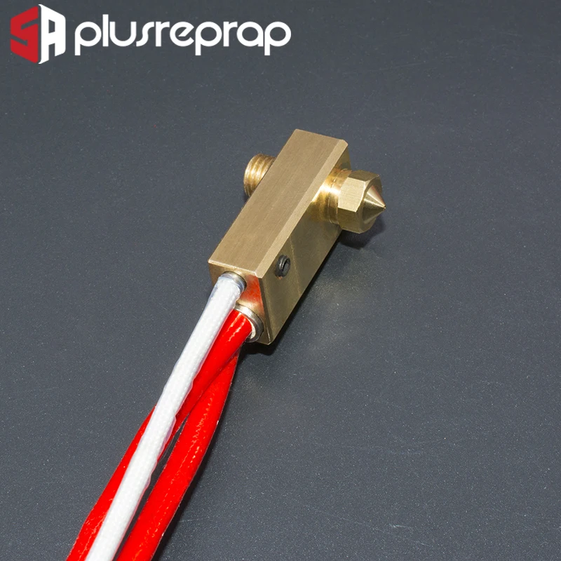 If this circuit is broken at the center, the open circuit network voltage (Seebeck voltage) is dependent on the degree of transition and the composition of the two metals. This means that when a PT100 thermocouple junction heats up or cools down, a voltage is created that can be correlated back to temperature.
Types of couples
Different combinations of thermocouples with calibrations are available. The most common are "Base Metal" thermocouples, known as types N, T, E, J, and K. There are also high temperature calibrations known as Noble Metal thermocouples - types R, S, C, and GB.
Note that thermocouple calibrations define temperature ranges. However, the maximum ranges of such a definition are limited by the diameters of the wires themselves. That is, a very thin thermocouple may not reach the full temperature range.
Type K thermocouples are known as general purpose thermocouples due to their low cost and temperature range.
How to choose the type of thermocouple?
Because thermocouples measure over wide temperature ranges and can be relatively rugged, thermocouples are very commonly used in industry.
The following criteria are used when selecting a thermocouple:
- temperature range;
- chemical resistance of thermocouple or sheath material;
- abrasive and vibration resistance;
- definition of response time.
The basic response time of a pair depends on the straight type and its material density. The usual stable density stress is 63%. In addition, in order to stepwise measure the step values at 100% determination, 5 time variables are required. Thermocouple types that have an open connection type respond much faster than the closed type. Another indicator is the diameter of the umbrella itself. The smaller it is, the greater the response, but this may affect the measurement temperature of a particular area.
How do I know which connection type to choose?
Available in 3 different designs.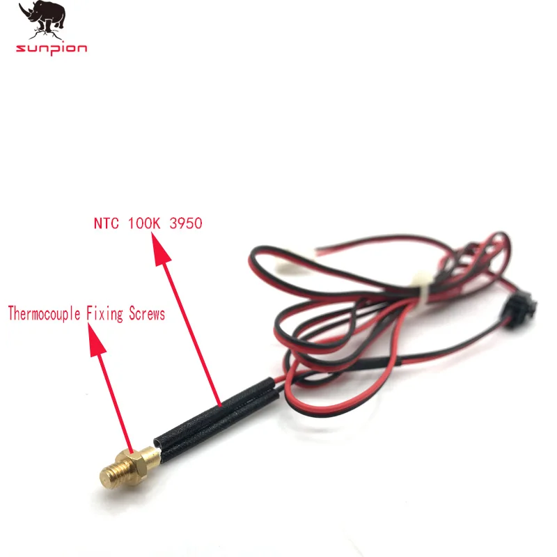
It can be:
- earthed;
- open;
- ground.
On ungrounded types of thermocouples, the probes are attached to the tips of the connecting drives by a physical method. Fixation is made on the inner wall of the probe. This allows a good transfer of heat from the outside from the probe itself to the thermocouple. The ungrounded type of thermocouple allows disconnection from the probe. At the same time, the response time is much lower than that of a grounded pair. However, it has much more electrical insulation.
The exposed thermocouple protrudes from the sheath tip and is exposed to the environment. This type provides the best response time, but limited use in non-corrosive and non-hermetic applications.
Earth connection recommended for measuring static or flowing corrosive gases and liquids and for high pressure applications. The grounded thermocouple connection is welded to the containment, providing a faster response than the ungrounded connection type.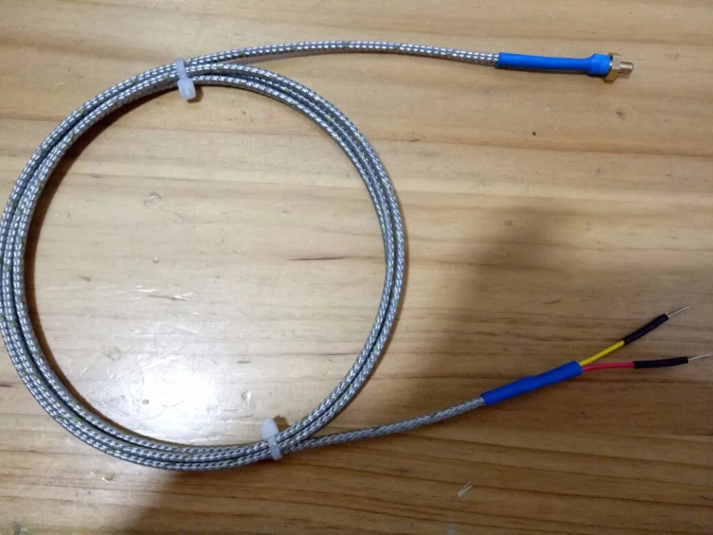
The emergency connection is recommended for measurements in harsh environments where it is desirable to have a thermocouple electronically isolated from the sheath and protected by the sheath. The weld wire thermocouple is physically isolated from the thermocouple sheath by MgO (soft) powder.
For measuring static or flowing non-aggressive gas temperatures, an open connection is recommended where a fast response time is required. The connection extends beyond the protective metal sheath to ensure accurate fast response. The shell insulation is sealed when the connection is expanded to prevent moisture or gas from entering, which could cause errors.
Temperature problems with 3D printer
top sellers
-
Bearing 604UU U604ZZ
U-bearing U604ZZ 604UU 4*13*4
35.00 UAH
-
Thermal mat for 3D printing 200 x 200 mm
3D printing thermal mat
150.
 00 UAH
 -
Buy epo3d+ 3D printer
Epo3d+ Ukrainian FDM 3D printer on HIWIN rails. Thanks to reliable...
UAH 35,000.00
-
ABS granules
ABS granules for extrusion
400.00 UAH
-
PLA
PLA environmental plastic from Plexiwire. 100% advance payment....
UAH 375.00
-
Buy ABS plastic (ABS)
ABS plastic from Plexiwire.
 100% prepayment. Free shipping...
 UAH 220.00
-
Mini motor reducer 12v 100 rpm
high torque mini electric motor. Its size...
150.00 UAH
-
Nozzle for 3D printer 1.75 mm, for E3D and MK8 hotends
Nozzle for 3D printer 1.75 mm 0.2/0.3/0.4/0.5
35.00 UAH
-
PETG plastic for 3D printer
PETG plastic from Plexiwire. 100% prepayment. Free...
UAH 360.00
-
SHF-20 shaft support
SHF-20 shaft support is used for CNC
60.
 00 UAH
 -
A4988 stepper motor driver
35.00 UAH
-
Buy epo3d 3D printer
Ukrainian epo3d 3D printer built on the basis of modern kinematics...
UAH 18,000.00
All best sellers
categories
Information
Problems with temperature during the operation of a 3D printer
In the article we will try to analyze in detail the issues that arise with temperature fluctuations during the operation of a 3D printer. Below are the most common problems and questions from 3D printer users. Thousands of hours of professional 3D printing behind our back to help you master your 3D printer.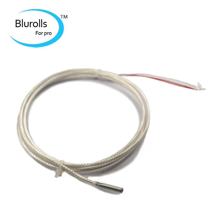
Hotend temperature fluctuates around set temperature
Please note that fluctuations of up to ± 10 °C around the set temperature during preheating and printing are considered normal.
After initial heating, the 3D printer firmware has a proportional-integral derivative (PID) control algorithm that stabilizes when it reaches ±10°C from the target temperature. The PID controller also helps maintain the temperature during printing.
If there are frequent fluctuations that exceed 10 °C, or alignment takes more than 2 minutes, when stabilizing to the set temperature, first make sure that the fans are installed correctly, the head and temperature sensor must be free of plastic residue. Possibly the PID is not calibrated.
Calibrate it like this:
1. Connect your 3D printer to your computer via USB.
2. Launch Repetier Host (Pronterface) and connect to the printer.
3. Use command [M303 C8 S235] (C = cycles and S = set temperature) and wait for it to start and return with measured values [kp] [ki] [kd] on the console.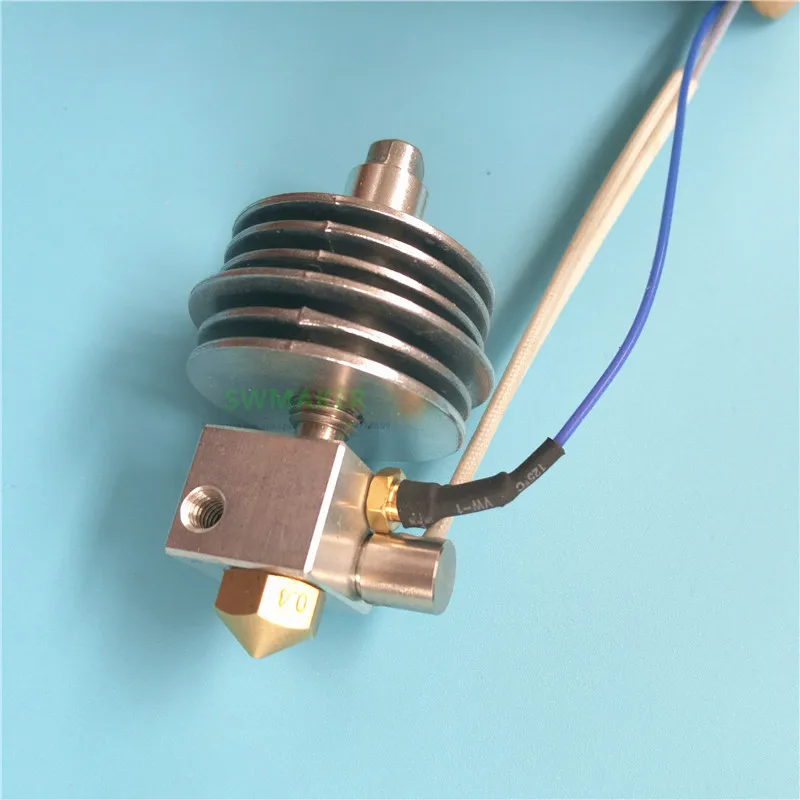 The more cycles (C), the more accurate the calibration can be.
4. On the printer control panel, navigate to Configuration => EEPROM Configuration and change the [PID-P] [PID-I] [PID-D] values.
5. Click OK to save the new PID settings.
Heating problems
Temperature does not increase
Indicates a problem with the ceramic heater on the print head.
Perform the troubleshooting steps:
Use a multimeter and measure the resistance across its terminals. A measurable resistance will show that it is working properly. A resistance of -1 would indicate that the heater itself is damaged.
Check for poor connections at all points between heater and control board.
Check if the ceramic heating plate in the heating block is cracked.
Temperature reading 0°C
Indicates a problem with the thermistor. To check if it is damaged, use a multimeter to measure the resistance across its terminals.