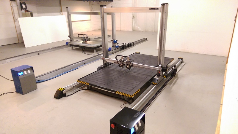
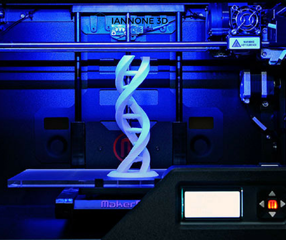
Split large 3d prints
How to Split & Cut STL Models For 3D Printing – 3D Printerly
Splitting and cutting your models or STL files for 3D printing is important if you want to create prints that are larger than your build plate. Instead of scaling down your project, you can separate your model into different parts which can later be joined together.
In order to split and cut your STL models for 3D printing, you can do this in many CAD software such as Fusion 360, Blender, Meshmixer, or even directly in slicers like Cura or Lychee Slicer. You simply select the split or cut function within the software and split the model where you choose.
This is the basic answer for splitting and cutting your model, so keep on reading to get the details on how to do this successfully, along with more useful information that you can use.
How Do You Break Up Models & STL Files for 3D Printing?
When it comes to 3D printing, breaking up large models is an important skill to learn since we are limited by the size of our build plates for each print.
Rather than stopping at this limitation, people figured out they could break models into smaller sections, which can then be glued back together afterwards. This can be done by using design software or even directly within our slicers, though it takes some knowledge to get it right.
It’s similar to having a model which is split with the main model and the base or stand of the model, but doing this for multiple parts of the model.
After you split and print the model, people tend to sand the prints down, then super glue them together to provide a strong bond that shouldn’t come apart.
Popular software that can split your STL files or models up are Fusion 360, Meshmixer, Blender, and many more. Some of these are easier than others, mainly due to the user interface or how many features the application has.
It’s best to pick a software and follow a good video tutorial that takes you through the steps to split up your models with ease. You can actually use the popular Cura slicer to split your models down and separate them into different STL files which can be printed separately.
Similarly, you have resin slicers such as ChiTuBox or Lychee Slicer that have inbuilt split functions where you can cut a model and organize it on the build plate as you wish.
The process of splitting a model and changing the orientation can allow you to easily fit a large model on your build plate, by utilizing the whole area.
In some instances with more advanced model, designers actually provide STL files where the model is already split up, especially when it comes to figurines, complex characters, and miniatures.
Not only are these models split up nicely, but sometimes they have joints which fit together nicely like a socket, allowing you to easily glue them together. With experience and practice, you can even take STL files, edit them and make your own joints.
Let’s look into how to actually split models using different software.
How to Split a Model in Fusion 360
A simple way to split a model in Fusion 360 is to sketch where you want to split the model, Extrude the sketch towards the inside of your model, then change the Operation to “New Body”.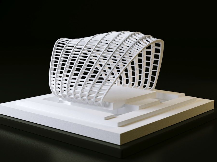 Now you can hit the “Split Body” button with the Splitting Tool highlighted and select the model to split up the two separate parts.
Another way to split a model in Fusion 360 is to create an Offset Plane on your model under the “Construct” section in your toolbar, then move the Plane to where you want to split the model. You then click the “Split Body” button in the toolbar and select the Plane to cut. Each face of your model can have a Plane.
Check out the video below for a great illustration and tutorial on how to get this done for your models.
The video above shows how to split really simple models, though for more complex ones, you may want to use a more advanced technique to get the splits perfect.
The video below by Product Design Online takes you through two main methods on how to split large STL files so you can successfully 3D print them. It works for STL files or even STEP files that are large meshes.
Many people describe it as one of the best videos on how to split 3D printer files for printing.
The first method consists of:
- Measuring the Model
- Turning on the Mesh Preview
- Using the Plane Cut Feature
- Selecting the Cut Type
- Selecting the Fill Type
The second method consists of:
- Using the Split Body Tool
- Moving the Newly Cut Parts
- Creating a Dovetail
- Copying the Joint Type: Making Duplicates
How to Split a Model in Cura
To split a model in Cura, you first have to download a plug-in called “Mesh Tools” from the Cura Marketplace. After getting it, you simply choose your model, click on the Extensions tab and find Mesh Tools there. Finally, click on “Split model into parts” and enjoy your model cut into two.
Cura’s method for splitting up a model is quite uncomplicated. The older versions of this slicer software didn’t even require downloading the Mesh Tools plug-in.
You simply had to right-click on the model and the option to split your model would appear. Painless360 has explained how to break your model into parts in the following video.
Unfortunately, Cura does not involve advanced techniques to cut your model. You’ll have to use Meshmixer or Fusion 360 for more complex part splitting.
How to Cut a Model in Half in Blender
To cut a model in half in Blender, go to “Edit Mode” by pressing the “Tab” key, then find the “Bisect Tool” in the “Knife” section on the left column. Ensure the mesh is selected by pressing “A” then click the first and second point to create a line where your model will be cut. Now press “P” to separate the model.
- Go into Edit Mode by pressing the Tab key
- On the left column, find the “Knife” tool, hold the left click and select the “Bisect Tool”
- Make sure the mesh is selected by pressing the “A” key
- Create the line by clicking the first and last point across your model to start the split
- Press the “V” key then right-click to make the actual split in the model
- While the split is still highlighted, press “CTRL+L” to select the active mesh it’s connected to.
- You can also hold “SHIFT” and click any meshes if there are loose parts then hit “CTRL+L” to select it
- Hit the “P” key and separate parts by “Selection” to separate the parts in the model
- Now you can hit “TAB” to go back to Object Mode and move around the two separate pieces.
There are some options that you can play with while splitting up your models, though it’s very simple to do for the most part.
You can choose whether you want to keep the part of the model you are splitting by checking the “Clear Inner” or “Clear Outer” part of the model, as well as choose whether to “Fill” the mesh, so the split doesn’t just have a gap in there.
If you forgot to fill in your models during the splitting process, you can hold “SHIFT + ALT” then Left-Click the outer mesh or edge of the model to select the whole exterior or “loop select” the model. Now press the “F” key to fill in the mesh.
There are more tips that you can do to smooth your model and even make the edges match up better. Check out the video below by PIXXO 3D for a great tutorial on how to split models on Blender.
How to Separate Objects in Meshmixer
When it comes to creating complex cuts, doing it in a slicer or very basic CAD software can be difficult or just not possible. Meshmixer is a popular CAD software that allows you to have a lot more control over how you separate and split your 3D printing files.
To separate objects in Meshmixer, you have to click on the “Edit” section and choose “Plane Cut” from the options there. Then, select “Slice” as the “Cut Type” and separate the object using a plane cut. Go back to “Edit” and click on “Separate Shells.” You will now be able to easily “Export” the individually split models from the menu on the left.
You also have a second option to split models by using the “Select Tool” and specifying a smaller area of the model to be cut.
Josef Prusa has a great video showing you exactly how you can cut STL models successfully in Meshmixer.
Here is a summary step-by-step guide to separating objects in Meshmixer.
- First, import your model into the Meshmixer platform
- Select “Edit” & hit “Plane Cut”
- Rotate the view to identify the Plane you want to cut
- Click and drag to cut the model in the desired area
- Change the “Cut Type” to slice so you don’t discard any of the model and hit “Accept”
- Your model is now separated
- You can go back to “Edit” and select “Separate Shells” to split the model up
Another cool thing you can do in Meshmixer is to actually create aligning pins to your split models which fit like a plug between two pieces. This is also shown in the video above, so definitely check that out to learn how to do it like the pros.
Bonus Method: Use 3D Builder to Split 3D Models Easily
3D Builder is one of the easiest ways of splitting up an STL file and cutting it into different parts. It comes pre-loaded on most Windows computers, and can also be downloaded for free through the Microsoft Store.
The application enjoys a fluid, responsive interface with easy-to-understand controls that even beginners won’t have a difficult time getting used to.
To split a model in 3D Builder, simply select your model, click on “Edit” in the Taskbar above, and then click on “Split.” You would then use the rotation gyroscopes to position the cutting plane however you want. When done, click on “Keep Both” and select “Split” to cut the model in half and save it as an STL file.
3D Builder makes the splitting process quite effortless for 3D printing enthusiasts and experts alike. The cutting plane is easy to handle, and you can easily use it as your go-to model slicer, as thousands of other people do.
The following video can help illustrate the process even further.
Three Tips When Splitting a Large Part for 3D Printing
TriMech Blog, 3D Printing, SOLIDWORKS
By Ricky Shannon on
When working with 3D printing, there are times when you just can’t get your part to fit inside of the build volume of your printer. You can flip your part around, run it on a funny angle, or even try scaling it…but at the end of the day, sometimes you just have to cut the part in half to make it work. Don’t worry, we will help you out by highlighting three common scenarios.
Big Bulky Boys
Our first instance is probably the most common. You have a large bulky part that is too long in one dimension to fit in the printer’s build envelope. For this method to work, the part must be one inch or thicker across the mid-section. Second, can the central portion of the part be sectioned through the length of the part and still have an even amount of mass on both sides. This is because we are going to use a stepped dovetail tool that cuts in a “Z” cross-section so you can split your part along two planes (the below picture will explain better than I can).
The dovetail cutting tool can be modeled in SOLIDWORKS and extruded using solids, or if you are inclined, you can create using surfacing techniques. It is also possible to model the cutting tool with draft, this will allow the parts to pull tighter as they are pressed together. You will need to accommodate for adhesive in your joint, and for this reason, we like to add between .010” and .020” of thickness to the cutting tool.
A primary benefit of using a dovetail is that it provides a substantial amount of mechanical hold on the joint, and pairing this with a stepped “Z” dovetail design, means that the joint can only easily be opened in one direction – taking much of the workload away from the adhesive.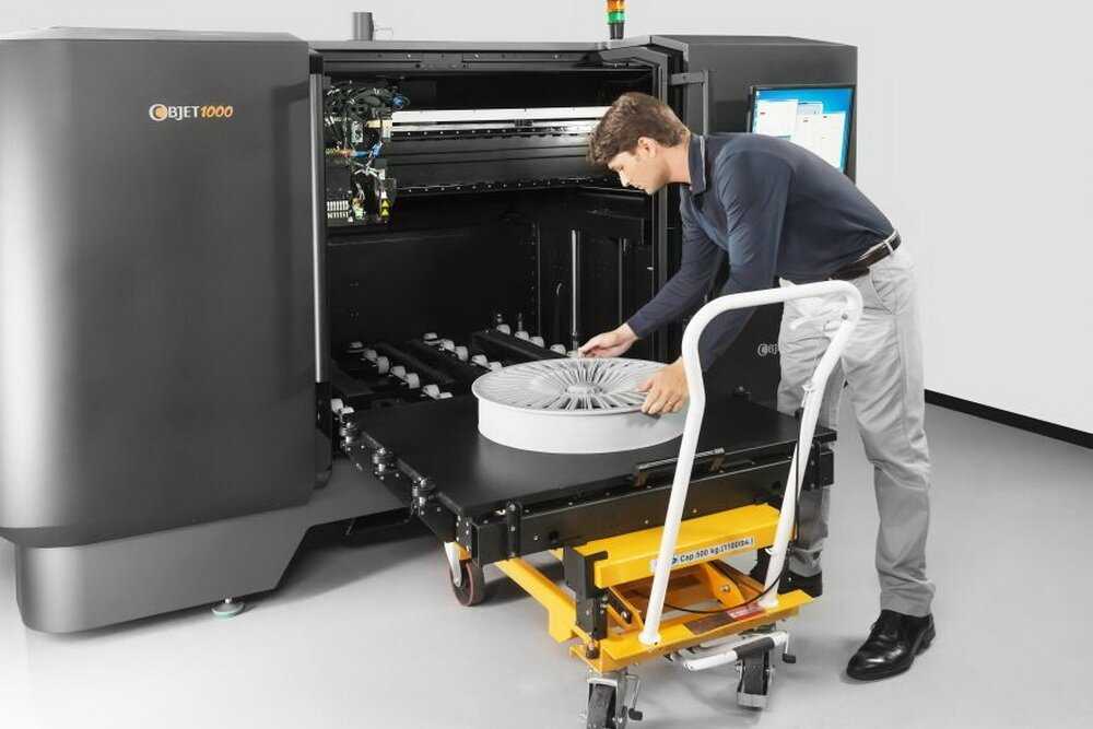
Pancake Parts
Not all parts are big and bulky. Sometimes you have thin parts or parts with very inconsistent cross-sections that won’t fit within the build volume of a printer. In these instances, a dovetail will be very difficult (if not impossible) to properly align and execute. These thin parts call for a convoluted solution……. literally, a convoluted solution. By creating a wavey-stepped cutting tool that runs in two-axis, you can form a large cutting tool that can be used on very thin and oddly shaped parts. Because of the lack of an interlocking feature on these convoluted joints, the joint can be positioned without concern on the part’s cross-sectional width (unlike a dovetail). A secondary benefit of these undulating surfaces is that the joint becomes self-aligning and exhibits greater surface area for adhesive. Unlike the dovetail, a joint of this design offers no real mechanical hold. All your eggs are in the adhesive’s basket.
So Much Support
The final splitting technique is not driven by the necessity to print parts beyond a printer’s capacity.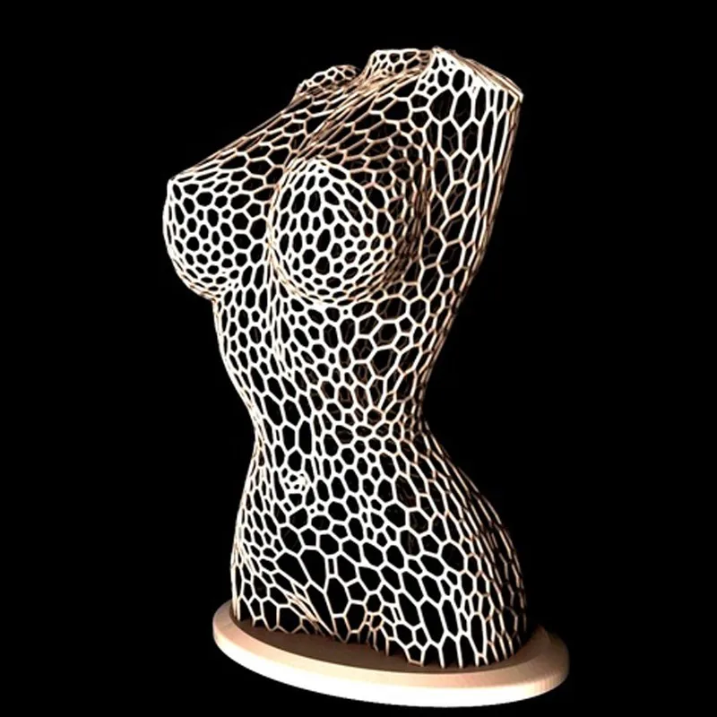 Instead, it’s an option to cut down on the amount of support used within a build. It’s common to have parts that require a large amount of support regardless of the orientation of the build.
Often, most of this support can be eliminated by splitting the part horizontally and printing the lower half. From there, flipped over with the cut side down as a separate part and finally adhering the two parts together. The key here is recognizing if the amount of labor to bond the parts together is worth the savings of eliminating the support on the build. This tends to be a worthwhile effort on larger parts and parts that tend to have a wide cross-sectional thickness along the planned cut.
In Conclusion
There are countless techniques and reasons to split parts and while we just scratched the surface on the topic. I hope these three common scenarios will help alleviate some of your part splitting woes. For more information on other splitting techniques, for example, SOLIDWORKS cutting tool files, or advice on how to best bond your split parts together, reach out to TriMech’s 3D Printing Team and we’d be happy to help!
Check out more of our 3D printing Video Tech Tips to expand your skills and learn more about other features and tools for 3D printingHow to create models that are larger than the print volume of a 3D printer
Don't have a large format 3D printer yet? When evaluating the capabilities of a compact desktop 3D printer, do not limit yourself to print volume.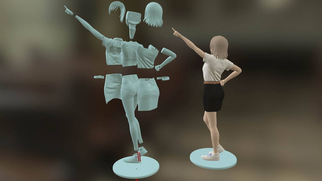 Many objects, like your smartphone or a bridge over a river, are made up of many individual components. Therefore, splitting the model into smaller parts that can be aligned after printing is a great solution for 3D printing large objects that do not fit on the platform. nine0003
Also, splitting the model can be a great way to get a high quality result, even if the whole model fits on the platform. This makes sense when multiple or opposing surfaces must be free from support structures, when the model has complex ledges, or contains cavities where liquid polymer can remain.
3D printing of various parts opens up new possibilities, for example, the creation of prefabricated structures from various materials or the combination of rigid and flexible parts to simulate the overmolding method. nine0003
When choosing a gluing method, it is necessary first of all to take into account the required degree of strength of the glued joints, which depends on the purpose of the models:
-
chemical: use adhesive on artwork, scale models, and complex shapes that are not intended for functional use and should not be impacted;
-
Mechanical: Provide threaded holes or sockets for attaching parts that require a secure mechanical connection, or repeatedly detaching and attaching components as needed.
 nine0003
This tutorial focuses on building large, prefabricated 3D stereolithographic (SLA) printed models with chemically bonded components. Read on to learn all the steps in this process, from model separation to post-processing for a professional finish.
Formlabs Form 3L is the first affordable, easy-to-use large format 3D printer optimized for reliable production of industrial-quality models. The Form 3L stereolithographic 3D printer features a huge print volume of 30 x 33.5 x 20 cm and unrivaled cost-effectiveness. nine0003
Meet the Form 3L
We recommend two ways to separate models: adding features to the design that will allow the parts to fit together, or separating the model with straight lines, which will require them to fit together properly during the bonding process.
Regardless of which method you choose, if you have a lot of parts, it's helpful to add a unique identifier (letters/numbers) for each one to make assembly easier.
nine0035
Use CAD software to split a 3D model and add basic centering components such as slots, pins, slots, notches, and tabs, or more complex features such as dovetails and slots to match model folds.
Adding centering components to the design makes it easier to assemble parts.
Ideally, these components should make it easier to align and assemble parts, but can cause problems if they differ even slightly from your 3D models, preventing perfect centering. Therefore, it is best to use centering components only when the printer can print parts with accurate dimensions that are not subject to deformation. nine0003
Splitting a 3D model along straight lines requires less effort than adding components to center it. With this separation method, there are also fewer problems if the parts are slightly deformed or differ in size.
Adding IDs for each part makes the assembly process easier.
On the other hand, parts separated by straight lines can be time consuming to assemble, as each part must be manually centered and ensured that they all remain in the correct position until the adhesive is completely dry.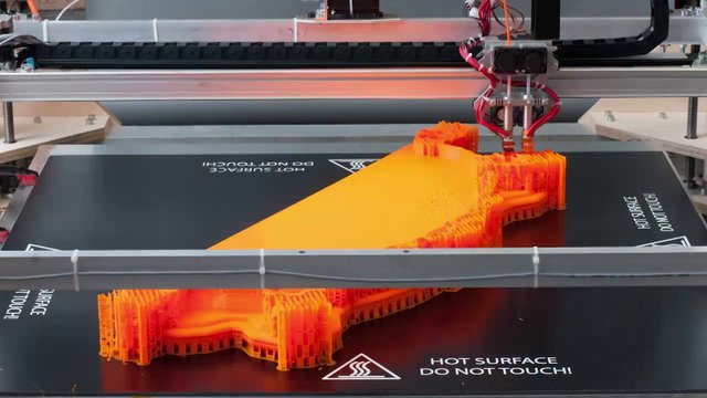 nine0003
By default, when printing on a stereolithographic 3D printer, solid models without voids are obtained. Depending on the design, different requirements may apply to the manufacture of large items. In such cases, 3D printing the outer shell or converting the structure into a hollow is a great way to save a lot of material and time. When printing hollow models on a stereolithographic 3D printer, be sure to add ventilation holes to avoid creating cavities filled with air and pressurized resin. nine0003
SAMPLE PART
Experience Formlabs print quality first hand. We will send a free sample of the printed model directly to your office.
Request a free print sample
Converting a model design to a hollow saves a lot of time and material because the printer only needs to print the outer shell.
Learn more about how to save materials and time by hollowing out 3D models.
Depending on the size of the details and the purpose of the model, we recommend three mounting methods:
| Epoxy glue (5-30 min) | cyanoacrylate (CCA, Supercollah) | Resin | ||||
|---|---|---|---|---|---|---|
Square. | Large | Small/Medium | Small | |||
| Paintable | Yes | Yes | Yes | 9006 70072Medium | Low | Low |
For large parts and maximum adhesion, use 5-30 minute dry epoxy. It takes longer to dry than other adhesives, allowing you to fit large 3D printed parts but slows down the assembly process. Most 5-minute epoxy adhesives stop changing shape in as little as five minutes and cure by about 75% in less than an hour.
For large parts and maximum adhesion we recommend using epoxy adhesive. nine0003
The next option is cyanoacrylate (CA or superglue), which quickly forms a strong bond, ideal for small to medium sized parts. Thoroughly clean the part before applying CA to the surface, because contaminants adversely affect the quality of the connection. CA has a moderate impact strength, but is not recommended for models that require high strength.
For small models, you can simply use liquid resin from a stereolithographic 3D printer. Pour a small amount of resin into a tray from a bottle or cartridge, pick it up with a pipette or syringe, and place it on the surface to be bonded. Connect the parts and wipe off excess resin that may spill around the edges. Aim a 5mW (405µm wavelength) UV laser pointer at the contact area to cure the resin and bond the parts. nine0003
This method produces a chemical bond similar to 3D stereolithography printing, but is only suitable for bonding small surfaces as a low power light pointer cannot penetrate the model deep enough to create a strong bond.
Note. Protective equipment must be worn when working with polymers, including proper eye protection and gloves.
Download PDF
Don't have time to read the article now? Download it in PDF format.
Download as PDF
After assembling the model, it's time to move on to post-processing. This step includes geometric correction of the model to provide a smooth surface that matches the original 3D model, and aesthetic finishing to obtain a uniformly colored surface.
Depending on the precision of the printer and the size of the printed parts, there will almost always be slight voids or mismatches at the contact points. Automotive sealant (e.g. Bondo 907) adheres well to polymers, therefore, to eliminate such inconsistencies, it is recommended to apply it in a thin layer on the surface. Lightly sand the surface after each coat has dried to bring the model to its final shape.
Sealing models with automotive sealant (red area in image) will help eliminate small gaps and inconsistencies between parts.
Sanding helps remove traces of support structures and remaining inconsistencies in the model. Gently start sanding the surface with 150-grit sandpaper to remove traces of support structures and smooth edges where parts meet. Once the surface is smooth, sand it wet using 320 grit sandpaper to remove any remaining layer lines. Sand the surface in random motions so as not to leave marks. In most cases, these two methods will produce a fairly smooth surface, but you can continue to increase the grit of the sandpaper up to 2 times and, after wetting it, sand the entire model until the surface is reasonably smooth. nine0003
Power sanding is great for large flat surfaces, but can ruin fine details. Grinding of small models is recommended to be done by hand, and for large ones, a combination of manual and mechanical grinding is recommended.
Machining large parts with mechanical and manual grinding saves a lot of time. Power sanding is great for large, flat surfaces, but can ruin the fine details, sharp corners, and subtle contours that are typical of stereolithography. As a result of mechanical grinding, a lot of dust is also generated, so before starting processing, it is necessary to prepare the working area. nine0003
Note. The use of power tools requires full attention and the use of protective equipment.
The surface can be damaged very quickly without even realizing it, just by leaving the sander without moving.
When finished sanding the model, rinse it in soapy water to remove dust and debris and dry thoroughly before proceeding to the last step.
The primer helps the paint adhere to the surface and can indicate areas where additional sanding is needed or removal of traces of supports that you may have missed. The Universal Matte Gray Plastic Primer shows these spots exceptionally well. For best results, apply it to the surface in several thin coats. Sand critical areas and reapply a thin coat of primer. Repeat this process until the entire surface of the model is level. nine0003
Note. Use protective equipment during priming and painting, including a respirator to protect against paint fumes.
All-purpose matt gray primer for plastics is exceptionally good at showing fine details and helping to identify areas that need to be sanded down.
Find out more about sanding and priming in our detailed guide.
When painting with multiple colors, protect the model with a temporary coat. First, plan the order in which you will paint the model, depending on the color, transparency, and size of the area of a particular color. Start with small details so that fewer of them can be protected when painting with the main color. Apply painter's tape to the edges and corners. To quickly cover large areas, attach sheets of paper to them. Ribbon guides (laser cut) can also be useful for creating straight lines, circles and complex shapes. nine0003
When it comes to masking, figuring out the correct order is your first priority. In our case, the parts were first painted silver and the sections that would remain silver on the final part were then covered with painter's tape to hide them from the next l
painting. In our case, we first painted the parts silver and put masking tape on the areas that should remain silver in the finished model so that they do not get paint of a different color. nine0003
As with primer, several thin coats of paint should be applied for optimal results rather than one thick coat. Most spray paints will achieve the best color in warm and slightly damp conditions in the absence of wind. In this case, you must always follow the manufacturer's recommendations, which can be given on the paint container or in the technical documentation.
Consider the time the paint needs to dry: Allow layers to settle before applying the same color and allow the paint to dry completely before applying a new color. nine0003
The area where we applied masking tape is still silver.
Become an expert in painting 3D models with our detailed guide
Already wondering what your finished model will look like?
"Sorry sir, that R2-D2 over there is in excellent condition and inexpensive."
Formlabs optics designer Adrien Tanner created this R2-D2 model from 105 parts printed on a Formlabs stereolithographic 3D printer. It even has working electronics borrowed from the Form 2 printer - a galvanometer drive for sound reproduction, a cartridge dispenser for lamps, and a Z-axis drive for dome rotation. nineThe 0003
Form 3L is the first large-format 30 x 33.5 x 20 cm 3D printer for producing massive, industrial-quality models.
Reduce order processing time when outsourcing or manual work when assembling large-scale 3D models. Now you can print large 3D models in their entirety on the Form 3L, the first affordable large format SLA printer.
Want to see how stereolithographic parts work? Explore our resources to learn more about stereolithographic resins, or request a free sample to evaluate print quality for yourself. nine0003
Request a free print sample
What if the model is too large to print? What program can be used to split a 3D model? / 3D printers, machines and accessories / iXBT Live
Sooner or later, every 3D printer user faces the problem of a small print area and what to do if you want to print large models, but the printer does not allow?
Divide them yourself and now I'll tell you how.
Paid program with which we will share our model. A program with a lot of features that you can familiarize yourself with and is very easy to use for beginners. nine0003
1. We load the model into Netfabb Ultimate and use the "x" "y" "z" sliders to indicate the location of our cut and press the scissors located below.
2. So that the figure does not warp during gluing, we will make fasteners. To do this, click Pin settings and configure the mounts.
3. After we undress the figure and save it.
4. Printing and enjoying
Open source 3D model slicer, it can also be used to divide models during print setup. This is not as convenient as in the method described above, but it is free. nine0003
1. Load the model and lower it below the print level.
2. Prepare the model for printing. The main thing is to remember the level to which the model was lowered.
Same 3D model slicer as Cura, but allows more fine-grained print settings.
1. Load the model and select the section of the model
2. Adjust the level of the section
3. Divide the model and prepare for printing
another of the above
1. Load the model into the workspace and press cut...
2. Next, select which part to print, adjust the top or bottom cut level and press perform cut
3. Cut the model and continue further configuration if necessary
The program for editing STL files and 3D meshes has a lot of functions for customizing
1. Load the model and select Edit from the menu on the left after Plane Cut
2. Adjust the cut level of the model
3. Cut the model and continue the print setup
I showed the easiest and most convenient ways to split the model into several parts for easier printing, but if you still have questions, write them in the comments.
News
Publications
Following the rest of the manufacturers, KbEar also decided to release tricky dynamic headphones with a completely new composite driver. They called the model Qinglong (read Qinglong), .